AUDI TT ROADSTER 2016 Owners Manual
Manufacturer: AUDI, Model Year: 2016, Model line: TT ROADSTER, Model: AUDI TT ROADSTER 2016Pages: 306, PDF Size: 31.82 MB
Page 271 of 306
Downloaded from www.Manualslib.com manuals search engine 0
N
,.....
N
......
0
,.....
Vl
CX) Mobility
General notes
.,.. If your vehicle experiences technical problems,
stop the car well away from moving traffic. If
you have a flat tyre, you should park the car on
a level surface. Be particularly careful if you are
on a slope .
.,.. Apply the parking brake .
.,.. Switch
the hazard warning lights on .
.,.. Place the warning triangle in a visible location
¢page 269.
.,.. Instruct all passengers to leave the car when it
is safe to do so. They should wait in a safe place
(for instance behind the roadside crash barrier).
A WARNING
You should note the procedure described
above for your own safety and that of other
road users.
Equipment Warning triangle
Applies to: vehicles with warning triangle
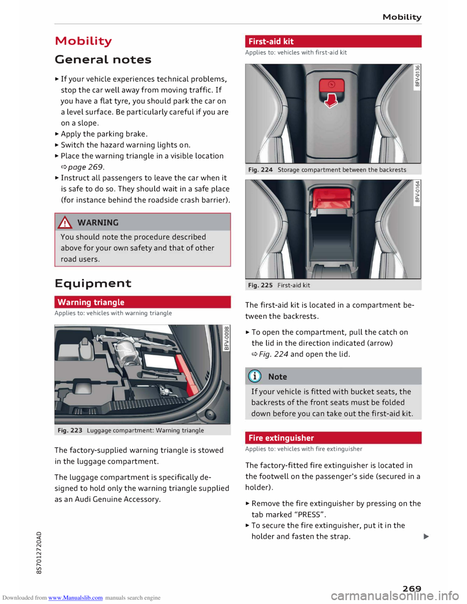
Fig. 223 Luggage compartment: Warning triangle
The factory-supplied warning triangle is stowed
in the luggage compartment.
The Luggage compartment is specifically de
signed to hold only the warning triangle supplied
as an Audi Genuine Accessory. Mobility
First-aid kit
Applies to: vehicles with first-aid kit
Fig. 224 Storage compartment between the backrests
Fig. 225 First-aid kit
The first-aid kit is located in a compartment be
tween the backrests .
.,.. To
open the compartment, pull the catch on
the Lid in the direction indicated (arrow)
¢ Fig. 224 and open the lid.
(©) Note
If your vehicle is fitted with bucket seats, the
backrests of the front seats must be folded
down before you can take out the first-aid kit.
Fire extinguisher
Applies to: vehicles with fire extinguisher
The factory-fitted fire extinguisher is located in
the footwell on the passenger's side (secured in a
holder).
.,.. Remove the fire extinguisher by pressing on the
tab marked "PRESS" .
.,.. To secure the fire extinguisher, put it in the
holder and fasten the strap.
269
Page 272 of 306
Downloaded from www.Manualslib.com manuals search engine Mobility
Check how the fire extinguisher works before you
need to use it. The instructions for use are shown
on the fire extinguisher.
A WARNING
If the fire extinguisher is not secured properly
it could be catapulted through the vehicle
during driving and braking manoeuvres or in
the event of an accident. This poses a risk of
injury to occupants.
(D Note
- The fire extinguisher must be replaced with
a new one after use or once it has reached
its expiry date.
- The fire extinguisher must comply with le
gal requirements.
Tool kit/tyre repair kit/compressor
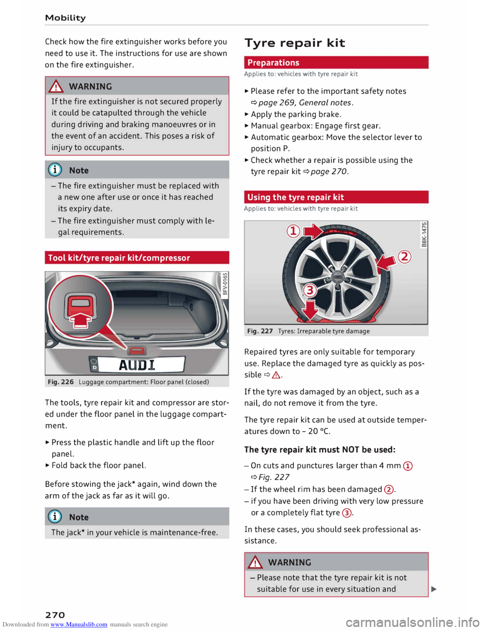
Fig. 226 Luggage compartment: Floor panel (closed)
The tools, tyre repair kit and compressor are stor
ed under the floor panel in the luggage compart
ment.
.., Press the plastic handle and lift up the floor
panel.
.., Fold back the floor panel.
Before stowing the jack* again, wind down the
arm of the jack as far as it will go.
ij} Note
The jack* in your vehicle is maintenance-free.
270 Tyre
repair kit
Preparations
Applies to: vehicles with tyre repair kit
.., Please refer to the important safety notes
¢ page 269, General notes.
.., Apply the parking brake.
.., Manual gearbox: Engage first gear.
.., Automatic gearbox: Move the selector lever to
position P .
.., Check whether a repair is possible using the
tyre repair kit¢ page 270.
Using the tyre repair kit
Applies to: vehicles with tyre repair kit
Fig. 227 Tyres: Irreparable tyre damage
Repaired tyres are only suitable for temporary
use. Replace the damaged tyre as quickly as pos
sible ¢& .
If the tyre was damaged by an object, such as a
nail, do not remove it from the tyre.
The tyre repair kit can be used at outside temper
atures down to -20 °(.
The tyre repair kit must NOT be used:
- On cuts and punctures larger than 4 mm (D
¢Fig. 227
- If the wheel rim has been damaged @.
- if you have been driving with very low pressure
or a completely flat tyre@.
In these cases, you should seek professional as
sistance.
A WARNING
- Please note that the tyre repair kit is not
suitable for use in every situation and-
Page 273 of 306
Downloaded from www.Manualslib.com manuals search engine 0
N
,.....
N
......
0
,.....
Vl
CX) should
only be used as a temporary meas
ure.
- Do not allow the sealant to come into con
tact with your eyes, skin or clothing.
- If you do come into contact with the sealant
immediately rinse the eyes or skin affected
with clean water.
- Make sure you do not breathe in the fumes.
- If you accidentally swallow tyre sealant, im-
mediately rinse your mouth thoroughly and
drink a large amount of water. Do not in
duce vomiting. Immediately contact a doc
tor.
- Change clothing immediately if it becomes
soiled with the tyre sealant.
- If any allergic reactions should occur get
medical help immediately.
- Keep the sealant away from children.
(©) Note
- If sealant should leak out, leave it to dry.
When it has dried, you can pull it off like a
piece of foil.
- Observe the expiry date stated on the seal
ing compound can. Have the sealing com
pound exchanged by a qualified workshop.
- Interference to the radio reception may oc
cur when using the compressor*.
- Please observe the relevant regulations.
Tyre repairs
Applies to: vehicles with tyre repair kit
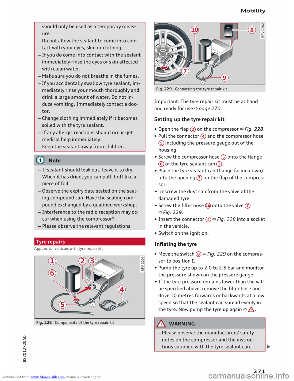
Fig. 228 Components of the tyre repair kit <.O
a,
N
0
> Mobility
Fig. 229 Connecting the tyre repair kit
Important: The tyre repair kit must be at hand
and ready for use ¢ page 2 70.
Setting up the tyre repair kit N
a,
N
0
>
� Open
the flap @on the compressor ¢ Fig. 228.
� Pull the connector © and the compressor hose
® including the pressure gauge out of the
housing.
� Screw the compressor hose® onto the flange
@ of the tyre sealant can@.
� Place
the tyre sealant can (flange facing down)
into the opening @ on the flap of the compres
sor.
� Unscrew the dust cap from the valve of the
damaged tyre.
� Screw the filler hose@ onto the valve 0
c:::>Fig. 229.
� Insert the connector ©¢ Fig. 228 into a socket
in the vehicle.
� Switch on the ignition.
Inflating the tyre
� Move the switch@ ¢ Fig. 229 on the compres
sor to position I.
� Pump the tyre up to 2.0 to 2.5 bar and monitor
the pressure shown on the pressure gauge.
� If the tyre pressure remains lower than the val
ue specified above, remove the filler hose and
drive 10 metres forwards or backwards at a low
speed so that the sealant can spread evenly in
the tyre. Now pump the tyre up again ¢ _A .
.&_ WARNING
- Please observe the manufacturers' safety
notes on the compressor and the instruc
tions supplied with the tyre sealant can.
271
Page 274 of 306
Downloaded from www.Manualslib.com manuals search engine Mobility
- If it was not possible to build up a tyre pres
sure of 2.0 bar within 6 minutes this means
that the tyre is too badly damaged. Do not
drive on.
- Seek professional assistance if the repair of
a tyre puncture is not possible with the seal
ing compound.
{D Note
Do not use the compressor for longer than
6 minutes at a time, as it could overheat.
When the compressor has cooled down, you
can use it again.
After repairing a tyre
Applies to: vehicles with tyre repair kit
.,. Affix the sticker "max. 80 km/h", which is inclu
ded in the tyre repair kit, to the dashboard
where the driver will see it.
.,. After about 10 minutes, stop to check the tyre
pressure .
.,. If
tyre pressure is less than 1.3 bar, the tyre is
too badly damaged. Do not drive on.
A WARNING
After repairing a tyre please note the follow
ing points:
- Do not drive faster than 80 km/h.
-Avoid heavy acceleration, hard braking and
fast cornering.
- Vehicle handling could be impaired.
- If the tyre is too badly damaged, you should
seek professional assistance.
® For the sake of the environment
A used can of sealing compound can be re
turned to your qualified workshop for dispos
al.
@ Note
After repairing a tyre, remember to buy a new
tyre sealant can at a qualified workshop.
272 Changing
a wheel
Preparations
Certain preparations must be made before you
change the wheel.
.,. Please refer to the important safety notes
¢ page 269, General notes.
.,. Apply the
parking brake .
.,. Manual gearbox: Engage first gear.
.,. Automatic gearbox: Move the selector lever to
position P.
.,. Take out the
tools ¢ page 2 70 and spare wheel
¢page 276.
A WARNING
If you have to use the jack* on a gradient or
off-road track, block the wheel diagonally op
posite the wheel being changed by placing
suitable objects underneath both the front
and rear of the wheel to prevent the vehicle
from rolling away.
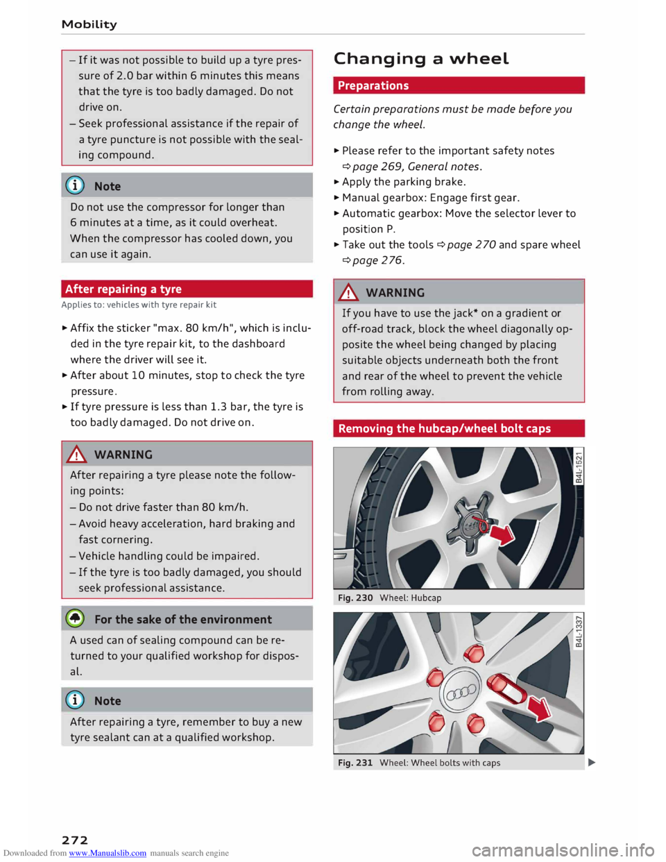
Removing the hubcap/wheel bolt caps -
Page 275 of 306
Downloaded from www.Manualslib.com manuals search engine 0
N
,.....
N Hubcaps*
�
Insert the hook (provided in the vehicle's tool
kit) in the hole in the hubcap ¢ Fig. 230.
� Pull off the hubcap.
Wheels with wheel bolt caps*
� Slide the plastic clip (provided in the vehicle's
tool kit) onto the wheel bolt cap until it engag
es ¢Fig. 231.
� Pull off the cap using the plastic clip.
Anti-theft wheel bolts
Applies to: vehicles with anti-theft wheel bolts
1
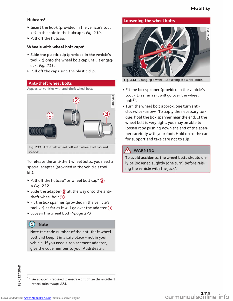
Fig. 232 Anti-theft wheel bolt with wheel bolt cap and
adapter <:t
CD
To release the anti-theft wheel bolts, you need a
special adapter (provided in the vehicle's tool
kit).
� Pull off the hubcap* or wheel bolt cap*@
¢Fig. 232.
� Slide
the adapter @ all the way onto the anti
theft wheel bolt@.
� Fit the box spanner (provided in the vehicle's
tool kit) as far as it will go over the adapter @.
� Loosen
the wheel bolt ¢ page 2 73.
(D} Note
Note the code number of the anti-theft wheel
bolt and keep it in a safe place -not in your
vehicle. If you need a replacement adapter,
give the code number to your Audi dealer.
8 l}An adapter is required to unscrew or tighten the anti-theft
,.....
� wheelbolts¢page273. Mobility
Loosening the wheel bolts
Fig. 233 Changing a wheel: Loosening the wheel bolts
� Fit
the box spanner (provided in the vehicle's
tool kit) as far as it will go over the wheel
bolt 1
>.
� Turn the wheel bolt approx. one turn anti
clockwise -arrow-. To apply the necessary tor
que, hold the box spanner near the end. If the
wheel bolt is very tight, you may be able to
Loosen it by pushing down the end of the span
ner carefully with your foot. Hold on to the car
for support and take care not to slip.
A WARNING
To avoid accidents, the wheel bolts should on
ly be Loosened slightly (one turn) before rais
ing the vehicle with the jack*.
273
Page 276 of 306
Downloaded from www.Manualslib.com manuals search engine Mobility
Raising the vehicle
Applies to: vehicles with jack
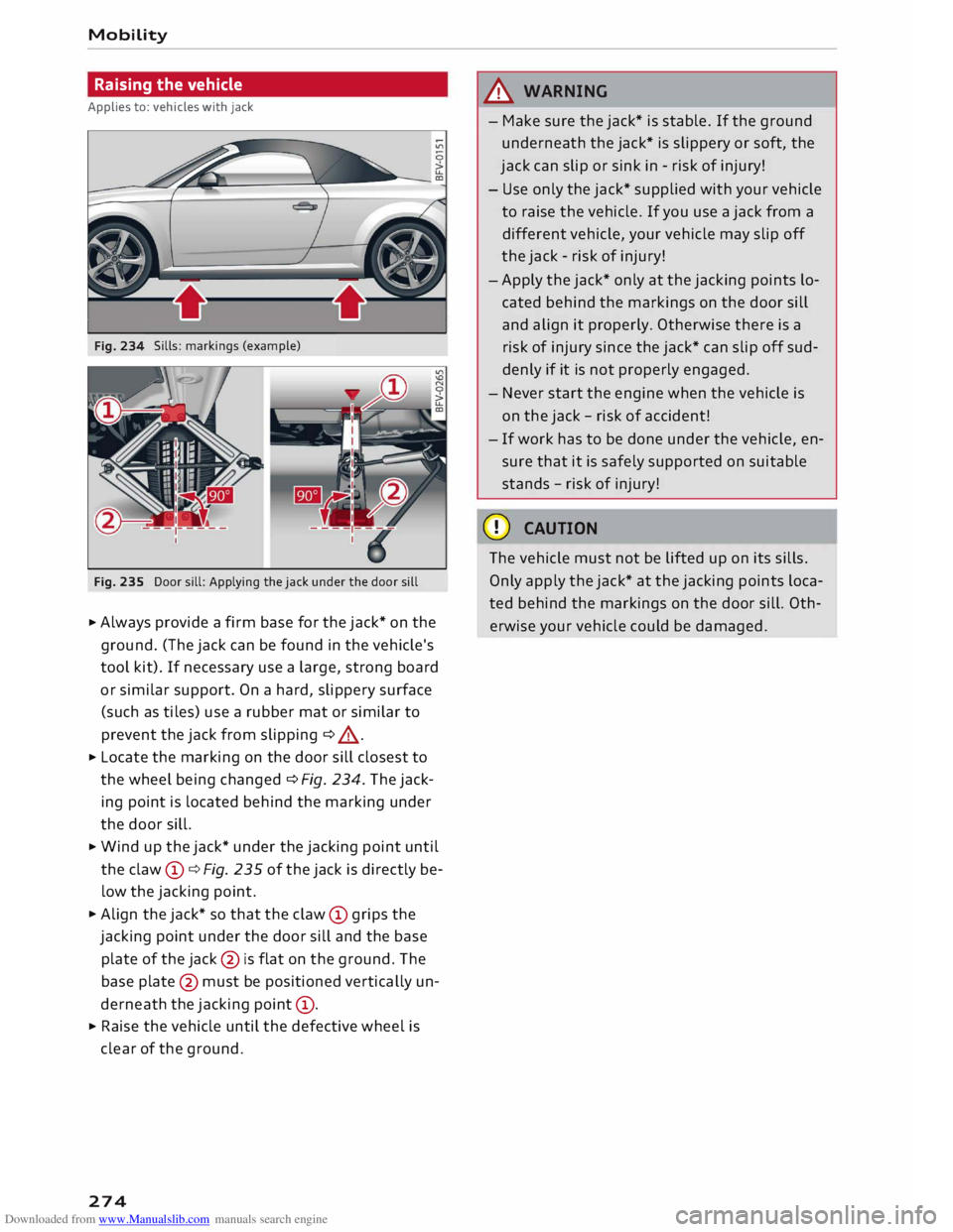
Sills: markings (example)
Fig. 235 Door sill: Applying the jack under the door sill
.., Always provide a firm base for the jack* on the
ground. (The jack can be found in the vehicle's
tool kit). If necessary use a large, strong board
or similar support. On a hard, slippery surface
(such as tiles) use a rubber mat or similar to
prevent the jack from slipping ¢ A .
.., Locate the marking on the door sill closest to
the wheel being changed ¢ Fig. 234. The jack
ing point is located behind the marking under
the door sill.
.., Wind up the jack* under the jacking point until
the claw (D
¢ Fig. 235 of the jack is directly be
low the jacking point .
.., Align the jack* so that the claw (D
grips the
jacking point under the door sill and the base
plate of the jack@
is flat on the ground. The
base plate @
must be positioned vertically un
derneath the jacking point (D
.
.., Raise the vehicle until the defective wheel is
clear of the ground.
274 .&_
WARNING
- Make sure the jack* is stable. If the ground
underneath the jack* is slippery or soft, the
jack can slip or sink in -risk of injury!
- Use only the jack* supplied with your vehicle
to raise the vehicle. If you use a jack from a
different vehicle, your vehicle may slip off
the jack -risk of injury!
-Apply the jack* only at the jacking points lo
cated behind the markings on the door sill
and align it properly. Otherwise there is a
risk of injury since the jack* can slip off sud
denly if it is not properly engaged.
- Never start the engine when the vehicle is
on the jack -risk of accident!
- If work has to be done under the vehicle, en
sure that it is safely supported on suitable
stands -risk of injury!
CD CAUTION
The vehicle must not be lifted up on its sills.
Only apply the jack* at the jacking points loca
ted behind the markings on the door sill. Oth
erwise your vehicle could be damaged.
Page 277 of 306
Downloaded from www.Manualslib.com manuals search engine Taking
off/ putting on the wheel
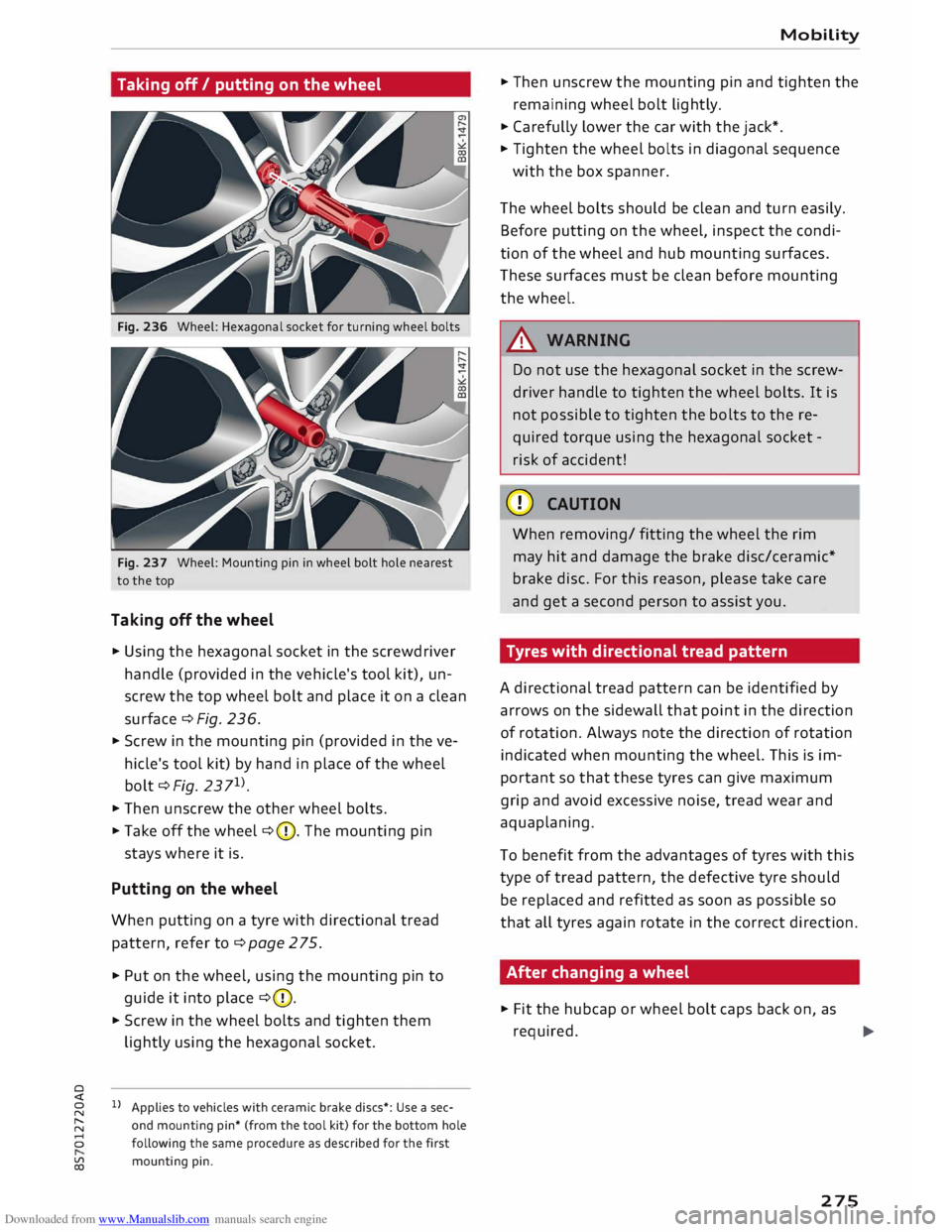
Fig. 236 Wheel: Hexagonal socket for turning wheel bolts
Fig. 237 Wheel: Mounting pin in wheel bolt hole nearest
to the top
Taking off the wheel
� Using the hexagonal socket in the screwdriver
handle (provided in the vehicle's tool kit), un
screw the top wheel bolt and place it on a clean
surface ¢ Fig. 236.
� Screw in the mounting pin (provided in the ve
hicle's tool kit) by hand in place of the wheel
bolt ¢Fig. 2371
).
� Then
unscrew the other wheel bolts.
�Take off the wheel ¢(D. The mounting pin
stays where it is.
Putting on the wheel
When putting on a tyre with directional tread
pattern, refer to ¢page 275.
� Put on the wheel, using the mounting pin to
guide it into place ¢(D.
� Screw in the wheel bolts and tighten them
lightly using the hexagonal socket.
0
Applies to vehicles with ceramic brake discs*: Use a sec-
� and
mounting pin* (from the tool kit) for the bottom hole
8 following the same procedure as described for the first
� mounting
pin. Mobility
� Then unscrew the mounting pin and tighten the
remaining wheel bolt lightly.
� Carefully lower the car with the jack*.
� Tighten the wheel bolts in diagonal sequence
with the box spanner.
The wheel bolts should be clean and turn easily.
Before putting on the wheel, inspect the condi
tion of the wheel and hub mounting surfaces.
These surfaces must be clean before mounting
the wheel.
.&_ WARNING
Do not use the hexagonal socket in the screw
driver handle to tighten the wheel bolts. It is
not possible to tighten the bolts to the re
quired torque using the hexagonal socket -
risk of accident!
CD CAUTION
When removing/ fitting the wheel the rim
may hit and damage the brake disc/ceramic*
brake disc. For this reason, please take care
and get a second person to assist you.
Tyres with directional tread pattern
A directional tread pattern can be identified by
arrows on the sidewall that point in the direction
of rotation. Always note the direction of rotation
indicated when mounting the wheel. This is im
portant so that these tyres can give maximum
grip and avoid excessive noise, tread wear and
aquaplaning.
To benefit from the advantages of tyres with this
type of tread pattern, the defective tyre should
be replaced and refitted as soon as possible so
that all tyres again rotate in the correct direction.
After changing a wheel
� Fit the hubcap or wheel bolt caps back on, as
required. ..,.
275
Page 278 of 306
Downloaded from www.Manualslib.com manuals search engine Mobility
...
Put the tools and jack back in the luggage com
partment.
... If the replaced wheel will not fit into the spare
wheel well, stow it safely in the luggage com
partment ¢page 227.
... Check
the tyre pressure of the fitted wheel as
soon as possible.
... Adjust the tyre pressures and store them via
the infotainment system.
... The
wheel bolts should be tightened to 120
Nm. Have this checked as soon as possible with
a torque wrench. Until then, drive with caution .
... Have the flat tyre replaced as quickly as possi
ble.
Spare wheel
General notes
Applies to: vehicles with compact temporary spare wheel
AUD!
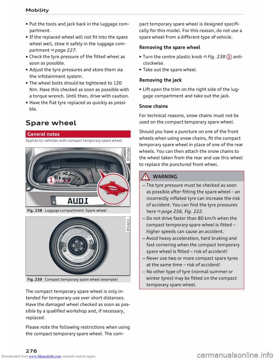
Fig. 238 Luggage compartment: Spare wheel
Fig. 239 Compact temporary spare wheel (example) ""
N
u..
co
The compact temporary spare wheel is only in
tended for temporary use over short distances.
Have the damaged wheel checked as soon as pos
sible by a qualified workshop and, if necessary,
replaced.
Please note the following restrictions when using
the compact temporary spare wheel. The com-
276 pact
temporary spare wheel is designed specifi
cally for this model. For this reason, do not use a
spare wheel from a different type of vehicle .
Removing the spare wheel
... Turn the centre plastic knob¢ Fig. 238 © anti-
clockwise.
... Take out the spare wheel.
Removing the jack
... Lift open the trim on the right side of the lug-
gage compartment and take out the jack.
Snow chains
For technical reasons, snow chains must not be
used on the compact temporary spare wheel.
Should you have a puncture on one of the front
wheels when using snow chains, fit the compact
temporary spare wheel in place of one of the rear
wheels. You can then attach the snow chains to
the wheel taken from the rear and use this wheel
to replace the punctured front wheel.
A WARNING
- The tyre pressure must be checked as soon
as possible after fitting the spare wheel -an
incorrectly inflated tyre can increase the risk
of accident. You can find the tyre pressures
here ¢ page 256, Fig. 222.
- Do not drive faster than 80 km/h when the
compact temporary spare wheel is fitted
higher speeds can cause an accident.
- Avoid heavy acceleration, hard braking and
fast cornering when the compact temporary
spare wheel is fitted -risk of accident!
- Never use two or more compact spare tyres
at the same time -risk of accident!
- No other type of tyre (normal summer or
winter tyres) may be fitted on the compact
temporary spare wheel.
Page 279 of 306
![AUDI TT ROADSTER 2016 Owners Manual Downloaded from www.Manualslib.com manuals search engine 0
<t
0
N
,.....
N
......
0
,.....
Vl
CX) ]ump-starting
Before starting the engine
If necessary, the engine can be started by AUDI TT ROADSTER 2016 Owners Manual Downloaded from www.Manualslib.com manuals search engine 0
<t
0
N
,.....
N
......
0
,.....
Vl
CX) ]ump-starting
Before starting the engine
If necessary, the engine can be started by](/img/6/57670/w960_57670-278.png)
Downloaded from www.Manualslib.com manuals search engine 0
N
,.....
N
......
0
,.....
Vl
CX) ]ump-starting
Before starting the engine
If necessary, the engine can be started by con
necting it to the battery of another vehicle.
If the engine fails to start because of a dis
charged battery, the vehicle battery can be con
nected to the battery of another vehicle to start
the engine. Suitable jump leads are required.
Both vehicle batteries must be rated at 12 Volts.
The capacity (Ah) of the booster battery should
not be significantly lower than that of the dis
charged battery.
Jump leads
The jump leads must be heavy enough to carry
the starter current. Refer to the details given by
the manufacturer.
Only use jump leads with insulated battery
clamps.
Positive cable -usually red.
Negative cable -usually black.
A WARNING
- When it is discharged the battery can freeze
at temperatures around 0°
(. A frozen bat
tery must first be thawed out before con
necting the jump leads -risk of explosion
and chemical burns! After jump-starting the
vehicle, drive to a qualified workshop with
out delay and have the vehicle battery
checked.
- Note the safety warnings referring to work
ing in the engine compartment ¢ page 244.
ij}) Note
- There must be no contact between the two
vehicles as otherwise current could flow as
soon as the positive terminals are connec
ted. This would discharge the boosting bat
tery.
- The discharged vehicle battery must be
properly connected to the vehicle's electri
cal system. Mobility
- Switch off the car telephone if necessary.
Details will be given in the manufacturer's
instructions for the car telephone.
Starting the engine
The two jump Leads must be connected in the
correct sequence.
Fig. 240 Engine compartment: Terminals for jump leads
and battery charger
Fig. 241 Jump-starting with the battery of another vehi
cle: A -Discharged battery, B -Boosting battery
Preparations
... Apply the parking brake and move the gear lev
er to neutral (manual gearbox) or move these
lector lever to P (automatic gearbox).
... Switch off all electrical equipment and the igni-
tion on both vehicles.
Connecting and disconnecting the jump
leads
... Before jump-starting the vehicle you must open
the cap on the positive terminal.
... Connect one end of the red jump lead to the
positive terminal (!) ¢Fig. 241 ofthejump
start connection @ in your vehicle.
... Connect the other end of the red jump lead to
the positive terminal @of the boosting battery
® · �
277
Page 280 of 306
Downloaded from www.Manualslib.com manuals search engine Mobility
...
Connect one end of the black lead to the nega
tive terminal @of the boosting battery@.
... Connect the other end of the black jump lead to
the negative terminal© of the jump-start con
nection @ in your vehicle.
... Position
the jump leads in such a way that they
cannot come into contact with any moving
parts in the engine compartment.
Starting the engine
... Start
the engine of the vehicle with the boost
ing battery and let it run at idling speed.
... Now start the engine of the vehicle with the
discharged battery.
... If the engine fails to start: do not operate the
starter for longer than 10 seconds. Wait for
about 30 seconds and try again .
... Switch on the blower and the rear window heat
ing on the vehicle which has been jump-started
in order to offset excessive voltage which may
occur when disconnecting the leads. The head
lights must be switched off!
... When
the engines are running, disconnect the
leads in exactly the opposite sequence to that
described on ¢page 277, Connecting and dis
connecting the jump Leads. Make sure that the
leads cannot come into contact with any mov
ing parts in the engine compartment.
... Close the cap on the positive terminal.
... Switch off the blower and the rear window
heating again.
A WARNING
- The non-insulated parts of the battery
clamps must not be allowed to touch. The
jump lead attached to the positive battery
terminal must not touch metal parts of the
vehicle: this can cause short circuits.
- Do not lean over batteries -risk of chemical
burns!
- The screw plugs on the battery cells must be
screwed in firmly.
- Keep sparks, flame and lit cigarettes away
from vehicle batteries: the gases given off
can cause an explosion.
- If jump-starting another vehicle, position
the jump leads in such a way that they can
not come into contact with any moving
278 parts
in the engine compartment of the oth
er vehicle .
CD CAUTION
Please note that the above method of con
necting the leads is intended for jump-start
ing your vehicle. If jump-starting another ve
hicle, you should not connect the negative
Lead(-) to the negative terminal of the dis
charged vehicle battery, but directly to the
engine block or a solid metal part bolted to
the engine block. If the battery of the other
vehicle does not have a gas vent, there is a
risk that a mixture of oxygen and hydrogen
gas can accumulate and cause an explosion.
@ Note
- The vehicle battery is vented to the outside
to prevent gases entering the vehicle's inte
rior.
- Connect the battery clamps so they have
good metal-to-metal contact with the bat
tery terminals.
Tow-starting / towing
away
General notes
Some experience is required to tow or tow-start a
vehicle, especially when using a tow-rope. Both
drivers should be familiar with the technique re
quired for towing. Inexperienced drivers should
not attempt to tow-start or tow away another ve
hicle.
Do not pull too hard with the towing vehicle and
take care to avoid jerking the tow-rope. When
towing off-road, there is always a risk that the
anchorage points may be overloaded.
Tow-bar I tow-rope
It is easier and safer to tow the vehicle with a
tow-bar. You should only use a tow-rope if you do
not have a tow-bar. It is advisable to use a tow
rope made of elastic synthetic fibre or similarly
elastic material.
�