BMW MOTORRAD G 650 GS 2010 Rider's Manual (in English)
Manufacturer: BMW MOTORRAD, Model Year: 2010, Model line: G 650 GS, Model: BMW MOTORRAD G 650 GS 2010Pages: 136, PDF Size: 1.73 MB
Page 81 of 136
Fastener, quick-releaseaxle, front
45 Nm
Remove the front-wheel stand.
Apply the front brake and firmlycompress the front forks sever-al times
Tighten axle clamping screw2to the specified torque.
Clamp, front quick-re-lease axle
23 Nm
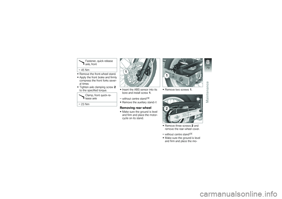
Insert the ABS sensor into itsbore and install screw1.
without centre standOE
Remove the auxiliary stand.
Removing rear wheel
Make sure the ground is leveland firm and place the motor-cycle on its stand.
Remove two screws1.
Remove three screws2andremove the rear-wheel cover.
without centre standOE
Make sure the ground is leveland firm and place the mo-
8
79
zMaintenance
Page 82 of 136
torcycle on a suitable auxiliarystand.
with centre standOE
Make sure the ground is leveland firm and place the motor-cycle on its centre stand.
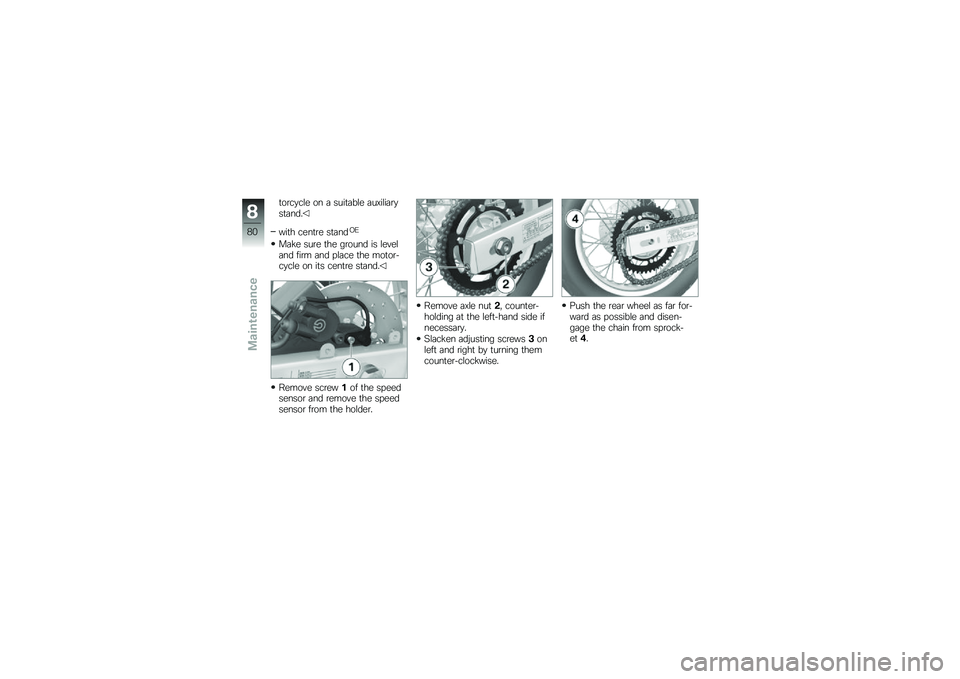
Remove screw1of the speedsensor and remove the speedsensor from the holder.
Remove axle nut2, counter-holding at the left-hand side ifnecessary.
Slacken adjusting screws3onleft and right by turning themcounter-clockwise.
Push the rear wheel as far for-ward as possible and disen-gage the chain from sprock-et4.
8
80
zMaintenance
Page 83 of 136
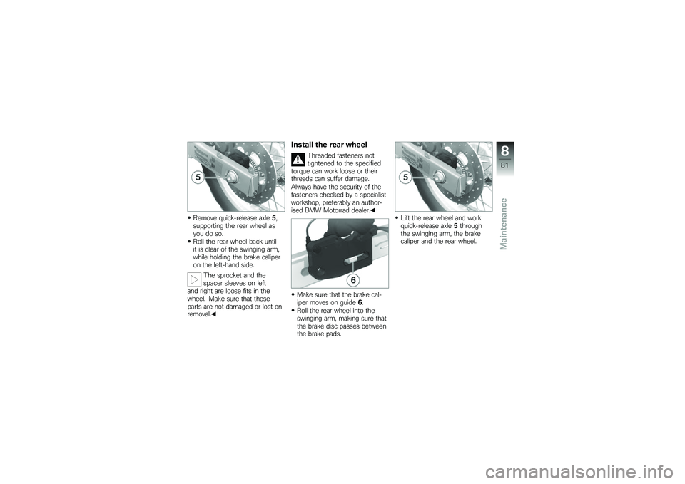
Remove quick-release axle5,supporting the rear wheel asyou do so.
Roll the rear wheel back untilit is clear of the swinging arm,while holding the brake caliperon the left-hand side.
The sprocket and thespacer sleeves on leftand right are loose fits in thewheel. Make sure that theseparts are not damaged or lost onremoval.
Install the rear wheel
Threaded fasteners nottightened to the specifiedtorque can work loose or theirthreads can suffer damage.
Always have the security of thefasteners checked by a specialistworkshop, preferably an author-ised BMW Motorrad dealer.
Make sure that the brake cal-iper moves on guide6.
Roll the rear wheel into theswinging arm, making sure thatthe brake disc passes betweenthe brake pads.
Lift the rear wheel and workquick-release axle5throughthe swinging arm, the brakecaliper and the rear wheel.
8
81
zMaintenance
Page 84 of 136
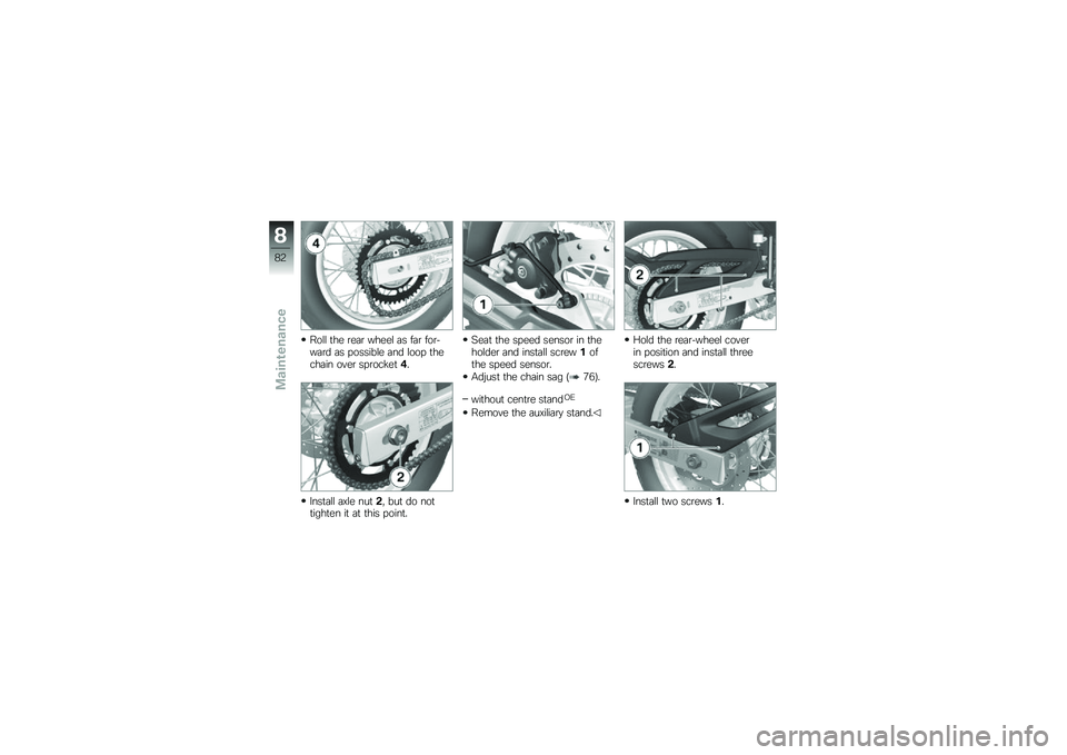
Roll the rear wheel as far for-ward as possible and loop thechain over sprocket4.
Install axle nut2, but do nottighten it at this point.
Seat the speed sensor in theholder and install screw1ofthe speed sensor.
Adjust the chain sag (76).
without centre standOE
Remove the auxiliary stand.
Hold the rear-wheel coverin position and install threescrews2.
Install two screws1.
8
82
zMaintenance
Page 85 of 136
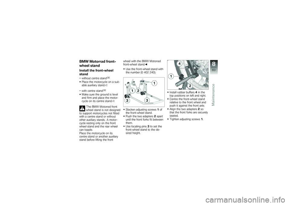
BMW Motorrad front-
wheel stand
Install the front-wheel
stand
without centre standOE
Place the motorcycle on a suit-able auxiliary stand.
with centre standOE
Make sure the ground is leveland firm and place the motor-cycle on its centre stand.
The BMW Motorrad frontwheel stand is not designedto support motorcycles not fittedwith a centre stand or withoutother auxiliary stands. A motor-cycle resting only on the frontwheel stand and the rear wheelcan topple.
Place the motorcycle on itscentre stand or another auxiliarystand before lifting the front
wheel with the BMW Motorradfront-wheel stand.
Use the front-wheel stand withthe number (0 402 240).
Slacken adjusting screws1ofthe front-wheel stand.
Push the two adapters2apartuntil the front forks fit betweenthem.
Use locating pins3to set thefront-wheel stand to the de-sired height.
Install rubber buffers4in thetop positions on left and right.
Centre the front-wheel standrelative to the front wheel andpush it against the front axle.
Align the two adapters2sothat the front forks are securelyseated.
Tighten adjusting screws1.
8
83
zMaintenance
Page 86 of 136
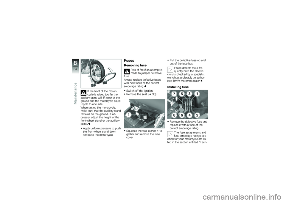
If the front of the motor-cycle is raised too far theauxiliary stand will lift clear of theground and the motorcycle couldtopple to one side.
When raising the motorcycle,make sure that the auxiliary standremains on the ground. If ne-cessary, adjust the height of thefront-wheel stand or the auxiliarystand.
Apply uniform pressure to pushthe front-wheel stand downand raise the motorcycle.
Fuses
Removing fuse
Risk of fire if an attempt ismade to jumper defectivefuse.
Always replace defective fuseswith new fuses of the correctamperage rating.
Switch off the ignition.
Remove the seat (38).
Squeeze the two latches1to-gether and remove the fusecover.
Pull the defective fuse up andout of the fuse box.
If fuse defects recur fre-quently have the electriccircuits checked by a specialistworkshop, preferably an author-ised BMW Motorrad dealer.
Installing fuse
Remove the defective fuse andreplace it with a fuse of thecorrect amperage rating.
The fuse assignments andfuse amperage ratings spe-cified for your motorcycle are lis-ted in the section entitled "Tech-
8
84
zMaintenance
Page 87 of 136
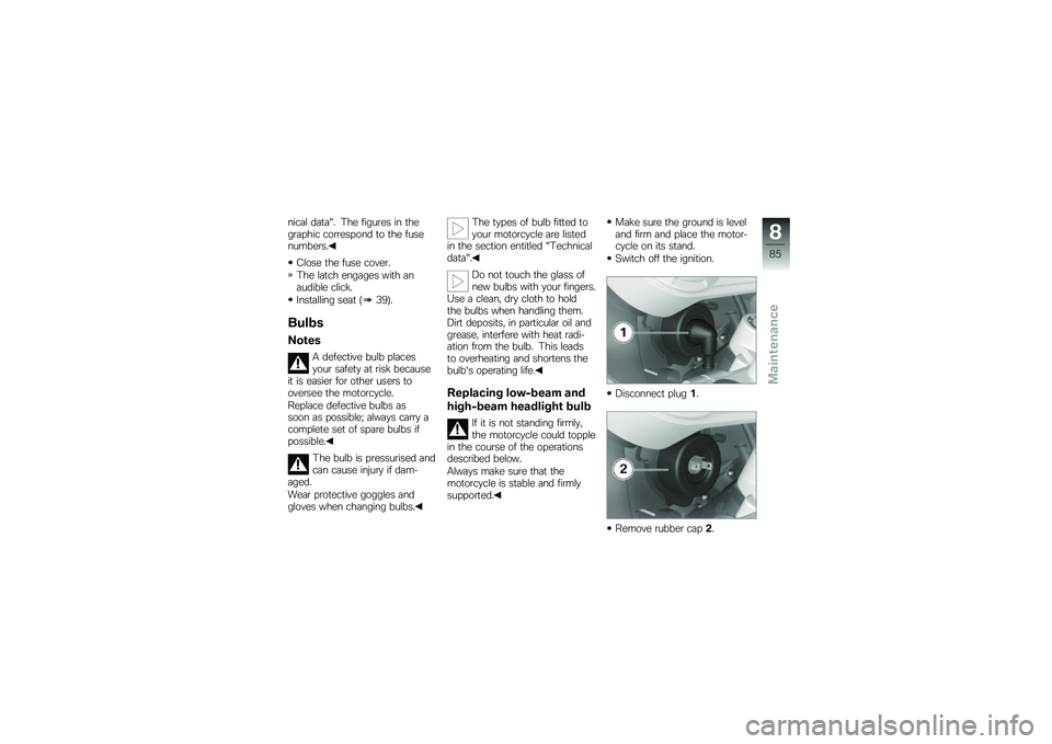
nical data". The figures in thegraphic correspond to the fusenumbers.
Close the fuse cover.
The latch engages with anaudible click.
Installing seat (39).
Bulbs
Notes
A defective bulb placesyour safety at risk becauseit is easier for other users tooversee the motorcycle.
Replace defective bulbs assoon as possible; always carry acomplete set of spare bulbs ifpossible.
The bulb is pressurised andcan cause injury if dam-aged.
Wear protective goggles andgloves when changing bulbs.
The types of bulb fitted toyour motorcycle are listedin the section entitled "Technicaldata".
Do not touch the glass ofnew bulbs with your fingers.Use a clean, dry cloth to holdthe bulbs when handling them.Dirt deposits, in particular oil andgrease, interfere with heat radi-ation from the bulb. This leadsto overheating and shortens thebulb's operating life.
Replacing low-beam and
high-beam headlight bulb
If it is not standing firmly,the motorcycle could topplein the course of the operationsdescribed below.
Always make sure that themotorcycle is stable and firmlysupported.
Make sure the ground is leveland firm and place the motor-cycle on its stand.
Switch off the ignition.
Disconnect plug1.
Remove rubber cap2.
8
85
zMaintenance
Page 88 of 136
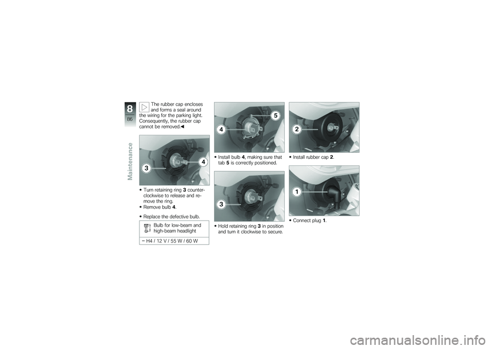
The rubber cap enclosesand forms a seal aroundthe wiring for the parking light.Consequently, the rubber capcannot be removed.
Turn retaining ring3counter-clockwise to release and re-move the ring.
Remove bulb4.
Replace the defective bulb.
Bulb for low-beam andhigh-beam headlight
H4 / 12 V / 55 W / 60 W
Install bulb4, making sure thattab5is correctly positioned.
Hold retaining ring3in positionand turn it clockwise to secure.
Install rubber cap2.
Connect plug1.
8
86
zMaintenance
Page 89 of 136
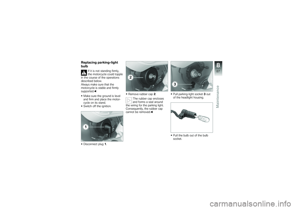
Replacing parking-light
bulb
If it is not standing firmly,the motorcycle could topplein the course of the operationsdescribed below.
Always make sure that themotorcycle is stable and firmlysupported.
Make sure the ground is leveland firm and place the motor-cycle on its stand.
Switch off the ignition.
Disconnect plug1.
Remove rubber cap2.
The rubber cap enclosesand forms a seal aroundthe wiring for the parking light.Consequently, the rubber capcannot be removed.
Pull parking-light socket3outof the headlight housing.
Pull the bulb out of the bulbsocket.
8
87
zMaintenance
Page 90 of 136
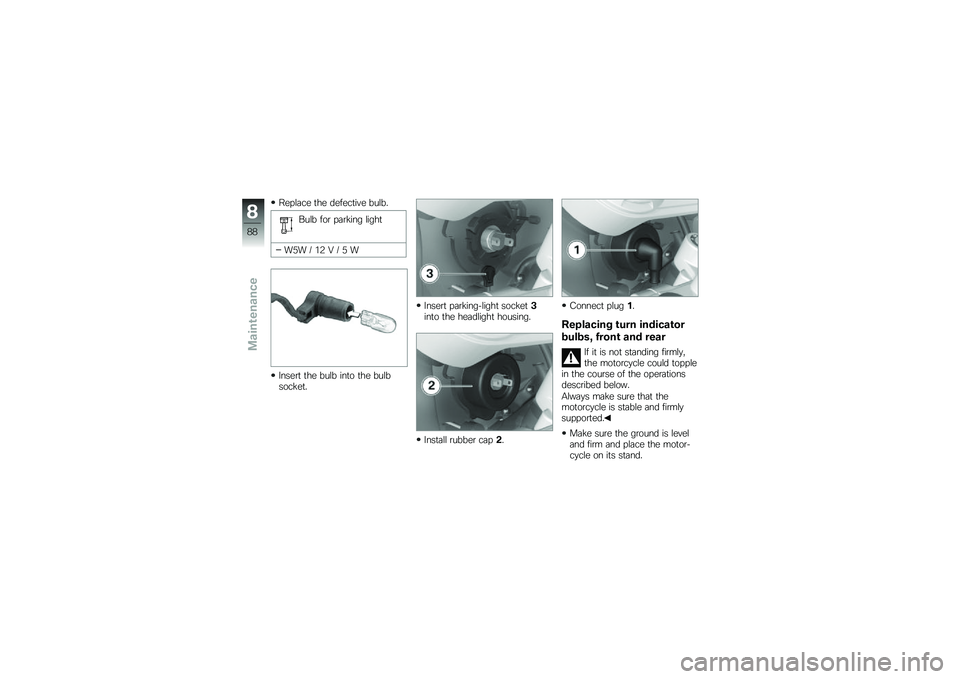
Replace the defective bulb.
Bulb for parking light
W5W / 12 V / 5 W
Insert the bulb into the bulbsocket.
Insert parking-light socket3into the headlight housing.
Install rubber cap2.
Connect plug1.
Replacing turn indicator
bulbs, front and rear
If it is not standing firmly,the motorcycle could topplein the course of the operationsdescribed below.
Always make sure that themotorcycle is stable and firmlysupported.
Make sure the ground is leveland firm and place the motor-cycle on its stand.
8
88
zMaintenance