CHERY TIGGO 2009 Service Owners Manual
Manufacturer: CHERY, Model Year: 2009,
Model line: TIGGO,
Model: CHERY TIGGO 2009
Pages: 1903, PDF Size: 33.38 MB
CHERY TIGGO 2009 Service Owners Manual
TIGGO 2009
CHERY
CHERY
https://www.carmanualsonline.info/img/53/56852/w960_56852-0.png
CHERY TIGGO 2009 Service Owners Manual
Trending: selector sensor, boot, center console, compression ratio, clock reset, set clock, high beam
Page 91 of 1903
Downloaded from www.Manualslib.com manuals search engine Assembly
1. Install the main bearings and thrust bearings to the upper cylinder block and lower cylinder block.NOTE: Identify and number the bearings, if reusing them, so that they are assembled in the same position and
direction.
2. Assemble the crankshaft and main bearings in the reverse order of disassembly.
ENGINE UNIT REPAIR
02–62Chery Automobile Co., Ltd.
Page 92 of 1903
Downloaded from www.Manualslib.com manuals search engine CYLINDER HEAD UNIT REPAIR
Cylinder Head
Specifications
Torque Specifications
DESCRIPTIONTORQUE (N·m)
Cylinder Head Bolts 1st Step: Tighten the bolt to 40 ± 5 N·m
2nd Step: Tighten the bolt an additional 90 ± 5° 3rd Step: Tighten the bolt an additional 90 ± 5°
Cylinder Head Cover Bolts 11
Clearance Specifications
DESCRIPTIONSPECIFICATION (mm)
Cylinder Head Flatness 0.04
Intake Valve Deflection 0.02
Exhaust Valve Deflection 0.04
Spring Height 47.7
Disassembly
NOTE :
The following special tools are required to perform the repair procedure:
•CH-20011 - Valve Seal Installer
• CH-20012 - Valve Stem Seal Installer Guide
• CH-20013 - Valve Seal Remover
• CH-20017 - Valve Keeper Installer
• CH-20018 - Valve Spring Compressor
NOTE :
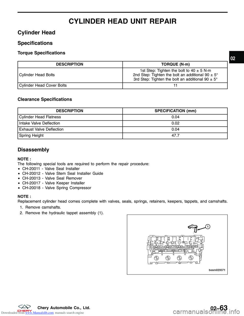
Replacement cylinder head comes complete with valves, seals, springs, retainers, keepers, tappets, and camshafts. 1. Remove camshafts.
2. Remove the hydraulic tappet assembly (1).
BESM020071
02
02–63Chery Automobile Co., Ltd.
Page 93 of 1903
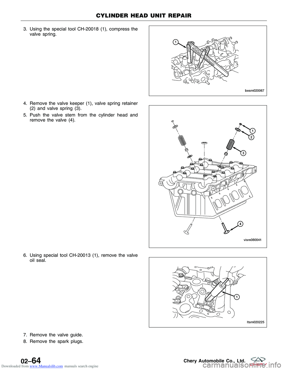
Downloaded from www.Manualslib.com manuals search engine 3. Using the special tool CH-20018 (1), compress thevalve spring.
4. Remove the valve keeper (1), valve spring retainer (2) and valve spring (3).
5. Push the valve stem from the cylinder head and remove the valve (4).
6. Using special tool CH-20013 (1), remove the valve oil seal.
7. Remove the valve guide.
8. Remove the spark plugs.
CYLINDER HEAD UNIT REPAIR
BESM020067
VISM080041
LTSM020225
02–64Chery Automobile Co., Ltd.
Page 94 of 1903
Downloaded from www.Manualslib.com manuals search engine Inspection
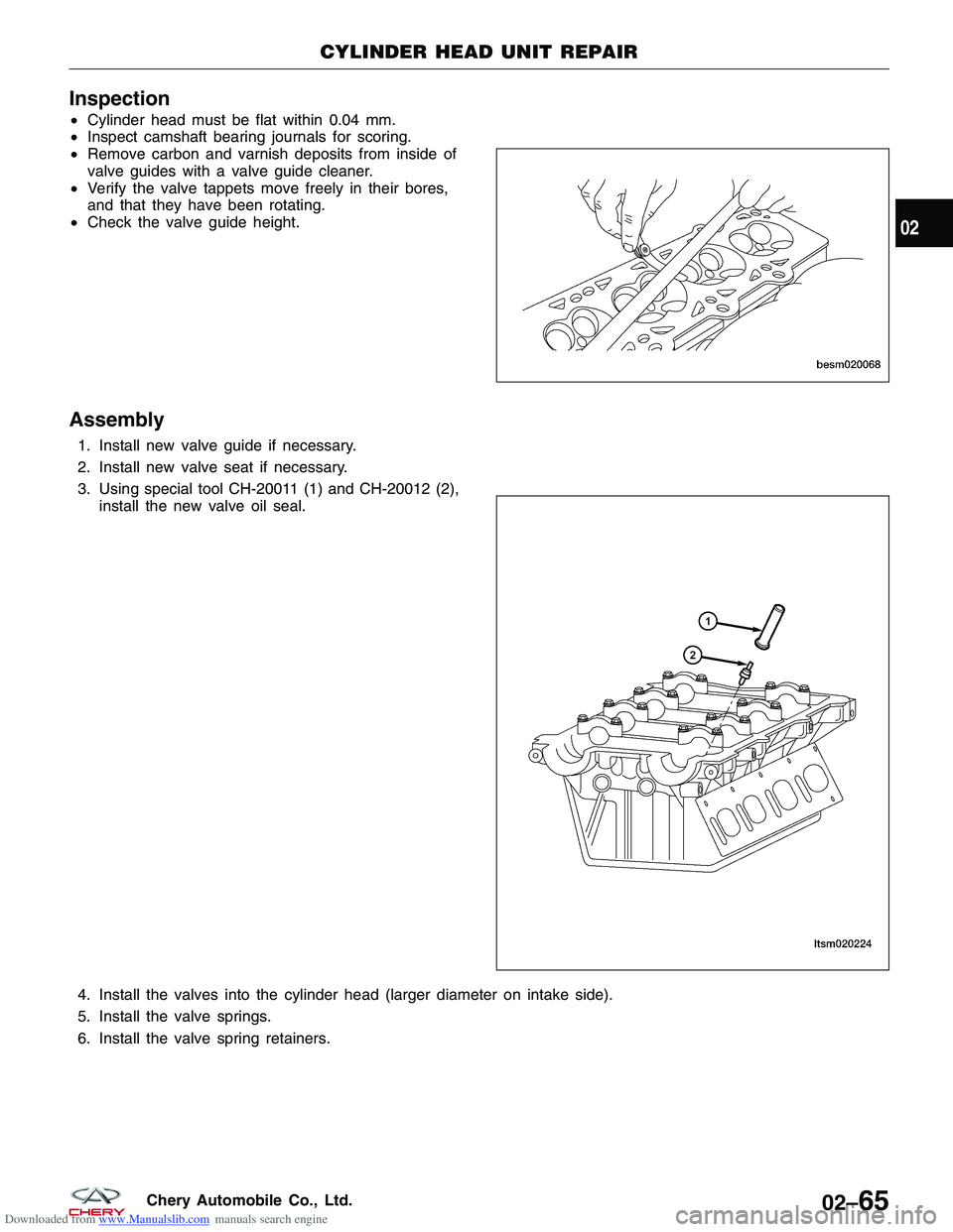
•Cylinder head must be flat within 0.04 mm.
• Inspect camshaft bearing journals for scoring.
• Remove carbon and varnish deposits from inside of
valve guides with a valve guide cleaner.
• Verify the valve tappets move freely in their bores,
and that they have been rotating.
• Check the valve guide height.
Assembly
1. Install new valve guide if necessary.
2. Install new valve seat if necessary.
3. Using special tool CH-20011 (1) and CH-20012 (2),
install the new valve oil seal.
4. Install the valves into the cylinder head (larger diameter on intake side).
5. Install the valve springs.
6. Install the valve spring retainers.
CYLINDER HEAD UNIT REPAIR
BESM020068
LTSM020224
02
02–65Chery Automobile Co., Ltd.
Page 95 of 1903
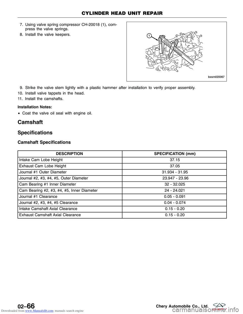
Downloaded from www.Manualslib.com manuals search engine 7. Using valve spring compressor CH-20018 (1), com-press the valve springs.
8. Install the valve keepers.
9. Strike the valve stem lightly with a plastic hammer after installation to verify proper assembly.
10. Install valve tappets in the head.
11. Install the camshafts.
Installation Notes:
• Coat the valve oil seal with engine oil.
Camshaft
Specifications
Camshaft Specifications
DESCRIPTION SPECIFICATION (mm)
Intake Cam Lobe Height 37.15
Exhaust Cam Lobe Height 37.05
Journal #1 Outer Diameter 31.934 - 31.95
Journal #2, #3, #4, #5, Outer Diameter 23.947 - 23.96
Cam Bearing #1 Inner Diameter 32 - 32.025
Cam Bearing #2, #3, #4, #5, Inner Diameter 24 - 24.021
Journal #1 Clearance 0.05 - 0.091
Journal #2, #3, #4, #5 Clearance 0.04 - 0.074
Intake Camshaft Axial Clearance 0.15 - 0.20
Exhaust Camshaft Axial Clearance 0.15 - 0.20
CYLINDER HEAD UNIT REPAIR
BESM020067
02–66Chery Automobile Co., Ltd.
Page 96 of 1903
Downloaded from www.Manualslib.com manuals search engine Disassembly
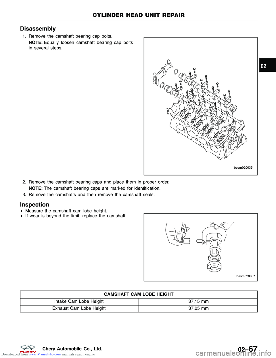
1. Remove the camshaft bearing cap bolts.NOTE: Equally loosen camshaft bearing cap bolts
in several steps.
2. Remove the camshaft bearing caps and place them in proper order. NOTE: The camshaft bearing caps are marked for identification.
3. Remove the camshafts and then remove the camshaft seals.
Inspection
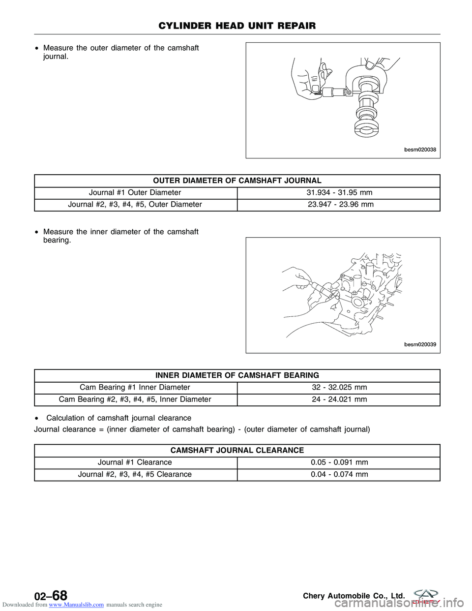
• Measure the camshaft cam lobe height.
• If wear is beyond the limit, replace the camshaft.
CAMSHAFT CAM LOBE HEIGHT
Intake Cam Lobe Height 37.15 mm
Exhaust Cam Lobe Height 37.05 mm
CYLINDER HEAD UNIT REPAIR
BESM020035
BESM020037
02
02–67Chery Automobile Co., Ltd.
Page 97 of 1903
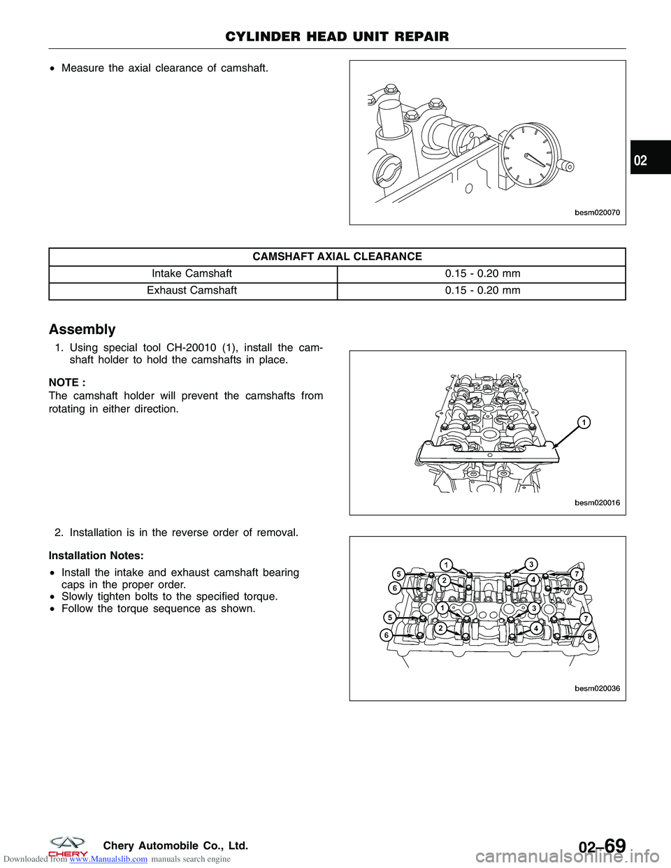
Downloaded from www.Manualslib.com manuals search engine •Measure the outer diameter of the camshaft
journal.
OUTER DIAMETER OF CAMSHAFT JOURNAL
Journal #1 Outer Diameter 31.934 - 31.95 mm
Journal #2, #3, #4, #5, Outer Diameter 23.947 - 23.96 mm
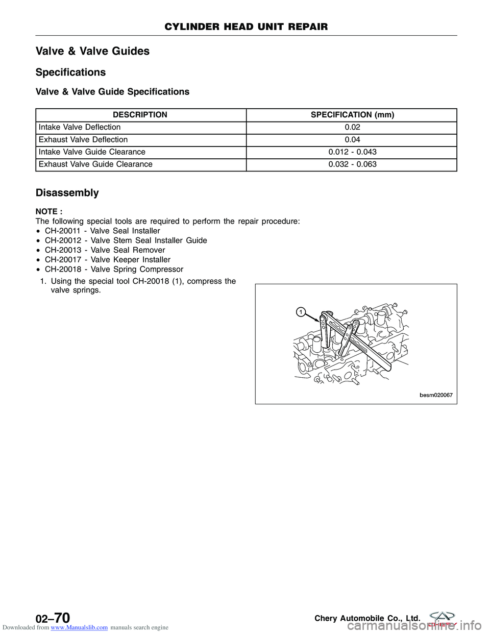
• Measure the inner diameter of the camshaft
bearing.
INNER DIAMETER OF CAMSHAFT BEARING
Cam Bearing #1 Inner Diameter 32 - 32.025 mm
Cam Bearing #2, #3, #4, #5, Inner Diameter 24 - 24.021 mm
• Calculation of camshaft journal clearance
Journal clearance = (inner diameter of camshaft bearing) - (outer diameter of camshaft journal)
CAMSHAFT JOURNAL CLEARANCE
Journal #1 Clearance 0.05 - 0.091 mm
Journal #2, #3, #4, #5 Clearance 0.04 - 0.074 mm
CYLINDER HEAD UNIT REPAIR
BESM020038
BESM020039
02–68Chery Automobile Co., Ltd.
Page 98 of 1903
Downloaded from www.Manualslib.com manuals search engine •Measure the axial clearance of camshaft.
CAMSHAFT AXIAL CLEARANCE
Intake Camshaft 0.15 - 0.20 mm
Exhaust Camshaft 0.15 - 0.20 mm
Assembly
1. Using special tool CH-20010 (1), install the cam-
shaft holder to hold the camshafts in place.
NOTE :
The camshaft holder will prevent the camshafts from
rotating in either direction.
2. Installation is in the reverse order of removal.
Installation Notes:
• Install the intake and exhaust camshaft bearing
caps in the proper order.
• Slowly tighten bolts to the specified torque.
• Follow the torque sequence as shown.
CYLINDER HEAD UNIT REPAIR
BESM020070
BESM020016
BESM020036
02
02–69Chery Automobile Co., Ltd.
Page 99 of 1903
Downloaded from www.Manualslib.com manuals search engine Valve & Valve Guides
Specifications
Valve & Valve Guide Specifications
DESCRIPTIONSPECIFICATION (mm)
Intake Valve Deflection 0.02
Exhaust Valve Deflection 0.04
Intake Valve Guide Clearance 0.012 - 0.043
Exhaust Valve Guide Clearance 0.032 - 0.063
Disassembly
NOTE :
The following special tools are required to perform the repair procedure:
•CH-20011 - Valve Seal Installer
• CH-20012 - Valve Stem Seal Installer Guide
• CH-20013 - Valve Seal Remover
• CH-20017 - Valve Keeper Installer
• CH-20018 - Valve Spring Compressor
1. Using the special tool CH-20018 (1), compress the valve springs.
CYLINDER HEAD UNIT REPAIR
BESM020067
02–70Chery Automobile Co., Ltd.
Page 100 of 1903
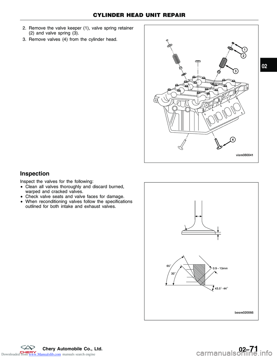
Downloaded from www.Manualslib.com manuals search engine 2. Remove the valve keeper (1), valve spring retainer(2) and valve spring (3).
3. Remove valves (4) from the cylinder head.
Inspection
Inspect the valves for the following:
• Clean all valves thoroughly and discard burned,
warped and cracked valves.
• Check valve seats and valve faces for damage.
• When reconditioning valves follow the specifications
outlined for both intake and exhaust valves.
CYLINDER HEAD UNIT REPAIR
VISM080041
BESM020066
02
02–71Chery Automobile Co., Ltd.
Trending: key, high beam, air conditioning, lights, wiring, keyless entry, ESP
