CHERY TIGGO 2009 Service Repair Manual
Manufacturer: CHERY, Model Year: 2009, Model line: TIGGO, Model: CHERY TIGGO 2009Pages: 1903, PDF Size: 33.38 MB
Page 271 of 1903
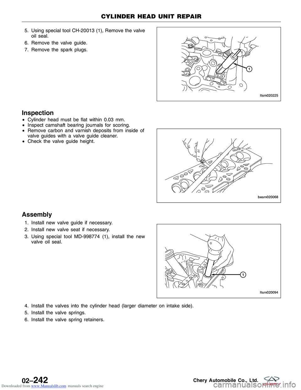
Downloaded from www.Manualslib.com manuals search engine 5. Using special tool CH-20013 (1), Remove the valveoil seal.
6. Remove the valve guide.
7. Remove the spark plugs.
Inspection
• Cylinder head must be flat within 0.03 mm.
• Inspect camshaft bearing journals for scoring.
• Remove carbon and varnish deposits from inside of
valve guides with a valve guide cleaner.
• Check the valve guide height.
Assembly
1. Install new valve guide if necessary.
2. Install new valve seat if necessary.
3. Using special tool MD-998774 (1), install the new
valve oil seal.
4. Install the valves into the cylinder head (larger diameter on intake side).
5. Install the valve springs.
6. Install the valve spring retainers.
CYLINDER HEAD UNIT REPAIR
LTSM020225
BESM020068 LTSM020094
02–242Chery Automobile Co., Ltd.
Page 272 of 1903
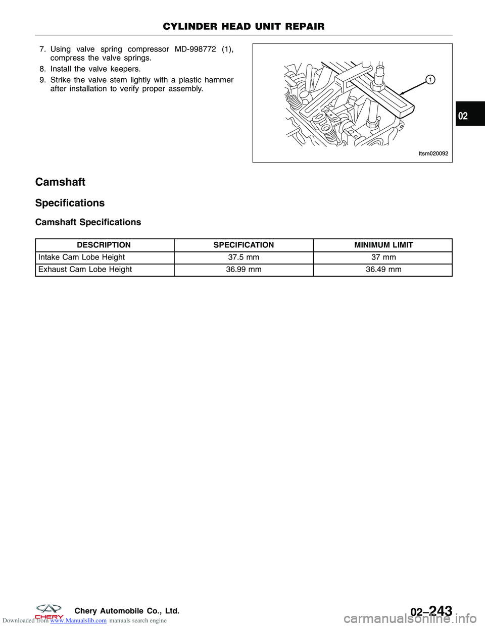
Downloaded from www.Manualslib.com manuals search engine 7. Using valve spring compressor MD-998772 (1),compress the valve springs.
8. Install the valve keepers.
9. Strike the valve stem lightly with a plastic hammer after installation to verify proper assembly.
Camshaft
Specifications
Camshaft Specifications
DESCRIPTION SPECIFICATION MINIMUM LIMIT
Intake Cam Lobe Height 37.5 mm37 mm
Exhaust Cam Lobe Height 36.99 mm36.49 mm
CYLINDER HEAD UNIT REPAIR
LTSM020092
02
02–243Chery Automobile Co., Ltd.
Page 273 of 1903
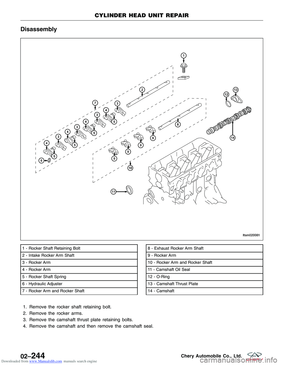
Downloaded from www.Manualslib.com manuals search engine Disassembly
1. Remove the rocker shaft retaining bolt.
2. Remove the rocker arms.
3. Remove the camshaft thrust plate retaining bolts.
4. Remove the camshaft and then remove the camshaft seal.
1 - Rocker Shaft Retaining Bolt
2 - Intake Rocker Arm Shaft
3 - Rocker Arm
4 - Rocker Arm
5 - Rocker Shaft Spring
6 - Hydraulic Adjuster
7 - Rocker Arm and Rocker Shaft8 - Exhaust Rocker Arm Shaft
9 - Rocker Arm
10 - Rocker Arm and Rocker Shaft
11 - Camshaft Oil Seal
12 - O-Ring
13 - Camshaft Thrust Plate
14 - Camshaft
CYLINDER HEAD UNIT REPAIR
LTSM020081
02–244Chery Automobile Co., Ltd.
Page 274 of 1903
Downloaded from www.Manualslib.com manuals search engine Camshaft
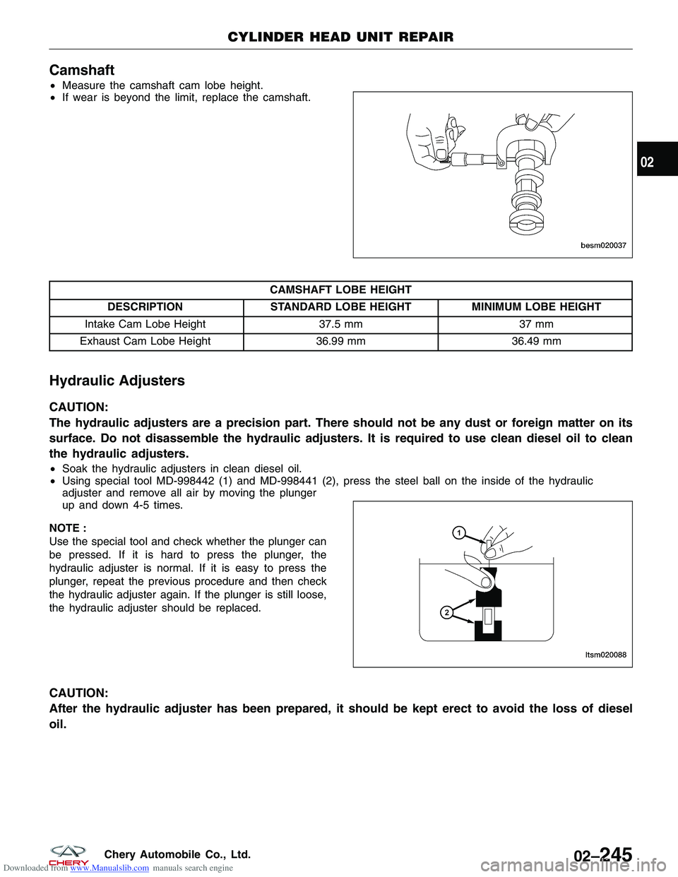
•Measure the camshaft cam lobe height.
• If wear is beyond the limit, replace the camshaft.
CAMSHAFT LOBE HEIGHT
DESCRIPTION STANDARD LOBE HEIGHT MINIMUM LOBE HEIGHT
Intake Cam Lobe Height 37.5 mm37 mm
Exhaust Cam Lobe Height 36.99 mm36.49 mm
Hydraulic Adjusters
CAUTION:
The hydraulic adjusters are a precision part. There should not be any dust or foreign matter on its
surface. Do not disassemble the hydraulic adjusters. It is required to use clean diesel oil to clean
the hydraulic adjusters.
•Soak the hydraulic adjusters in clean diesel oil.
• Using special tool MD-998442 (1) and MD-998441 (2), press the steel ball on the inside of the hydraulic
adjuster and remove all air by moving the plunger
up and down 4-5 times.
NOTE :
Use the special tool and check whether the plunger can
be pressed. If it is hard to press the plunger, the
hydraulic adjuster is normal. If it is easy to press the
plunger, repeat the previous procedure and then check
the hydraulic adjuster again. If the plunger is still loose,
the hydraulic adjuster should be replaced.
CAUTION:
After the hydraulic adjuster has been prepared, it should be kept erect to avoid the loss of diesel
oil.
CYLINDER HEAD UNIT REPAIR
BESM020037
LTSM020088
02
02–245Chery Automobile Co., Ltd.
Page 275 of 1903
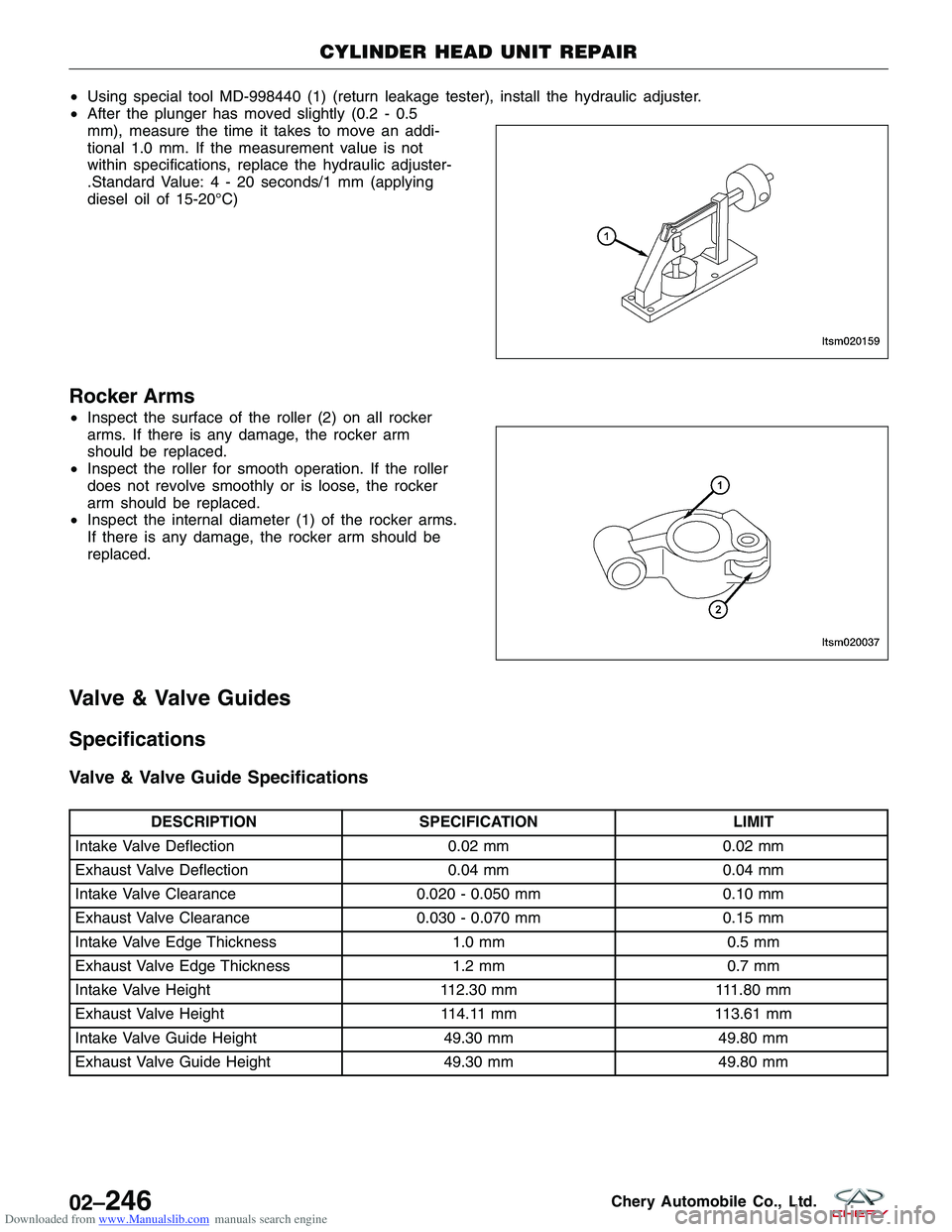
Downloaded from www.Manualslib.com manuals search engine •Using special tool MD-998440 (1) (return leakage tester), install the hydraulic adjuster.
• After the plunger has moved slightly (0.2 - 0.5
mm), measure the time it takes to move an addi-
tional 1.0 mm. If the measurement value is not
within specifications, replace the hydraulic adjuster-
.Standard Value:4-20seconds/1 mm (applying
diesel oil of 15-20°C)
Rocker Arms
•Inspect the surface of the roller (2) on all rocker
arms. If there is any damage, the rocker arm
should be replaced.
• Inspect the roller for smooth operation. If the roller
does not revolve smoothly or is loose, the rocker
arm should be replaced.
• Inspect the internal diameter (1) of the rocker arms.
If there is any damage, the rocker arm should be
replaced.
Valve & Valve Guides
Specifications
Valve & Valve Guide Specifications
DESCRIPTION SPECIFICATION LIMIT
Intake Valve Deflection 0.02 mm0.02 mm
Exhaust Valve Deflection 0.04 mm0.04 mm
Intake Valve Clearance 0.020 - 0.050 mm0.10 mm
Exhaust Valve Clearance 0.030 - 0.070 mm0.15 mm
Intake Valve Edge Thickness 1.0 mm0.5 mm
Exhaust Valve Edge Thickness 1.2 mm0.7 mm
Intake Valve Height 112.30 mm111.80 mm
Exhaust Valve Height 114.11 mm113.61 mm
Intake Valve Guide Height 49.30 mm49.80 mm
Exhaust Valve Guide Height 49.30 mm49.80 mm
CYLINDER HEAD UNIT REPAIR
LTSM020159
LTSM020037
02–246Chery Automobile Co., Ltd.
Page 276 of 1903
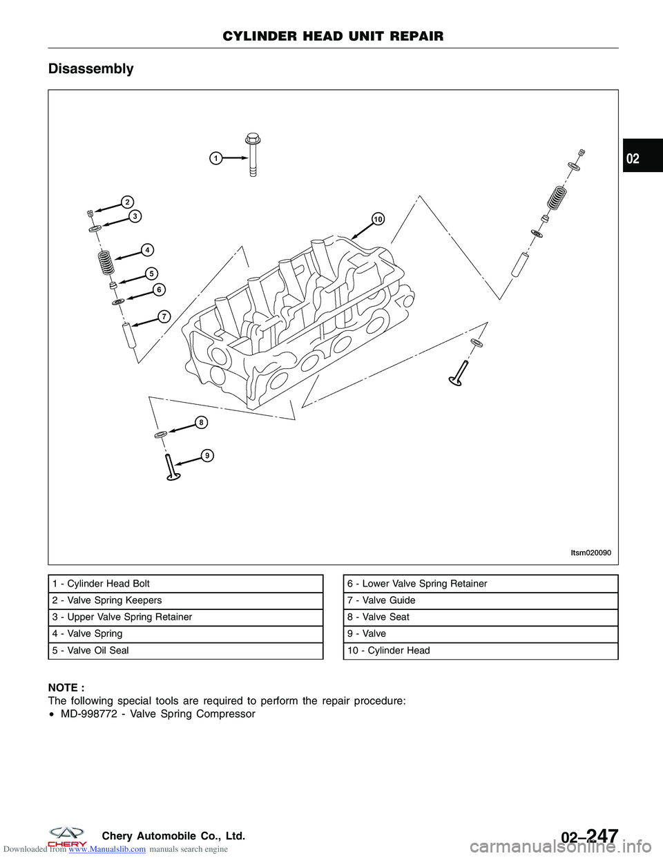
Downloaded from www.Manualslib.com manuals search engine Disassembly
NOTE :
The following special tools are required to perform the repair procedure:
•MD-998772 - Valve Spring Compressor
1 - Cylinder Head Bolt
2 - Valve Spring Keepers
3 - Upper Valve Spring Retainer
4 - Valve Spring
5 - Valve Oil Seal6 - Lower Valve Spring Retainer
7 - Valve Guide
8 - Valve Seat
9 - Valve
10 - Cylinder Head
CYLINDER HEAD UNIT REPAIR
LTSM020090
02
02–247Chery Automobile Co., Ltd.
Page 277 of 1903
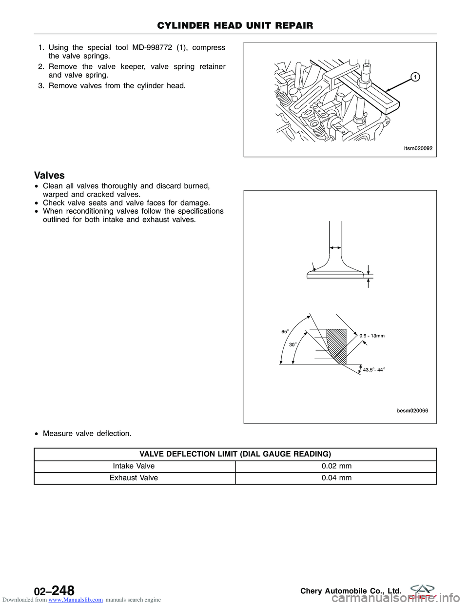
Downloaded from www.Manualslib.com manuals search engine 1. Using the special tool MD-998772 (1), compressthe valve springs.
2. Remove the valve keeper, valve spring retainer and valve spring.
3. Remove valves from the cylinder head.
Valves
• Clean all valves thoroughly and discard burned,
warped and cracked valves.
• Check valve seats and valve faces for damage.
• When reconditioning valves follow the specifications
outlined for both intake and exhaust valves.
• Measure valve deflection.
VALVE DEFLECTION LIMIT (DIAL GAUGE READING)
Intake Valve 0.02 mm
Exhaust Valve 0.04 mm
CYLINDER HEAD UNIT REPAIR
LTSM020092
BESM020066
02–248Chery Automobile Co., Ltd.
Page 278 of 1903
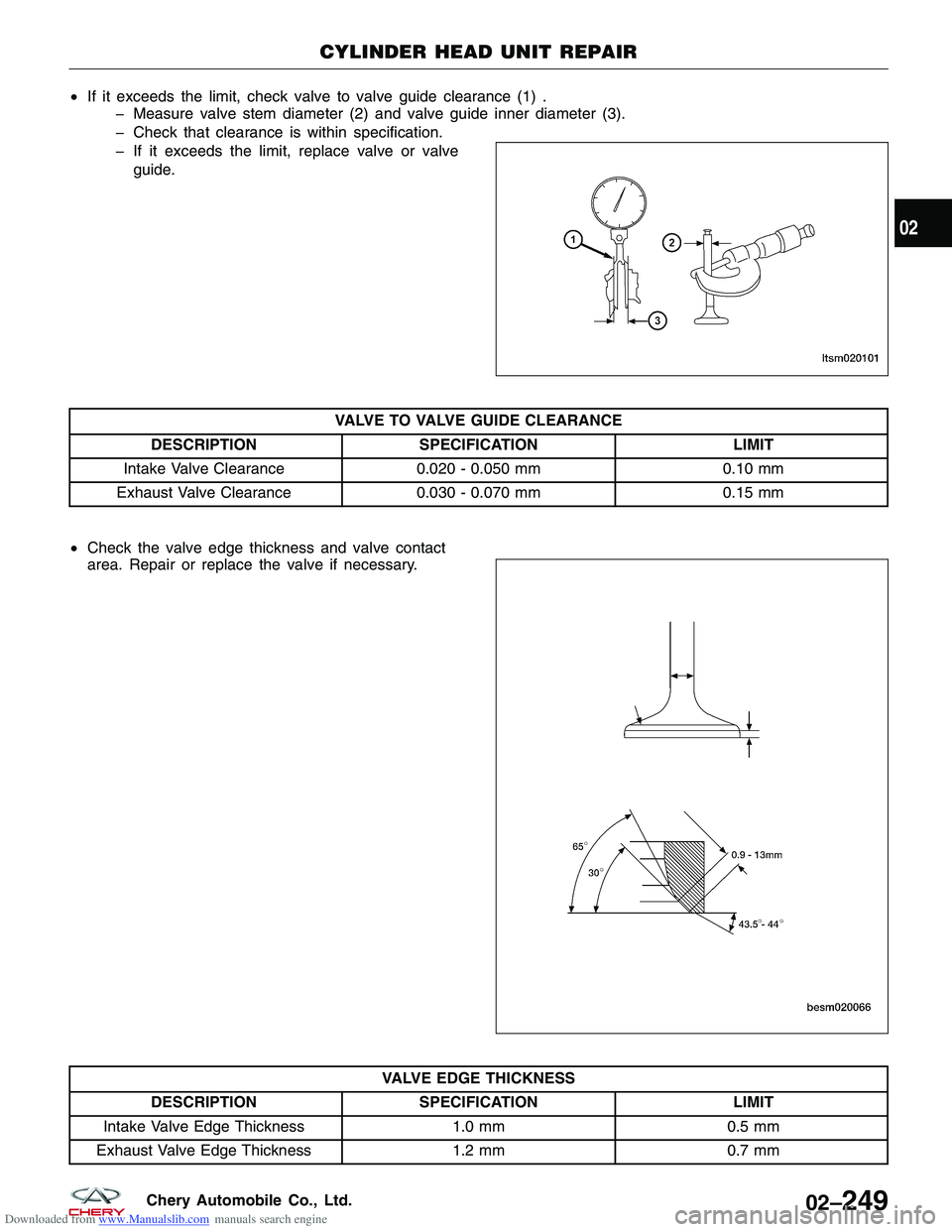
Downloaded from www.Manualslib.com manuals search engine •If it exceeds the limit, check valve to valve guide clearance (1) .
� Measure valve stem diameter (2) and valve guide inner diameter (3).
� Check that clearance is within specification.
� If it exceeds the limit, replace valve or valve
guide.
VALVE TO VALVE GUIDE CLEARANCE
DESCRIPTION SPECIFICATION LIMIT
Intake Valve Clearance 0.020 - 0.050 mm 0.10 mm
Exhaust Valve Clearance 0.030 - 0.070 mm 0.15 mm
• Check the valve edge thickness and valve contact
area. Repair or replace the valve if necessary.
VALVE EDGE THICKNESS
DESCRIPTION SPECIFICATION LIMIT
Intake Valve Edge Thickness 1.0 mm0.5 mm
Exhaust Valve Edge Thickness 1.2 mm0.7 mm
CYLINDER HEAD UNIT REPAIR
LTSM020101
BESM020066
02
02–249Chery Automobile Co., Ltd.
Page 279 of 1903
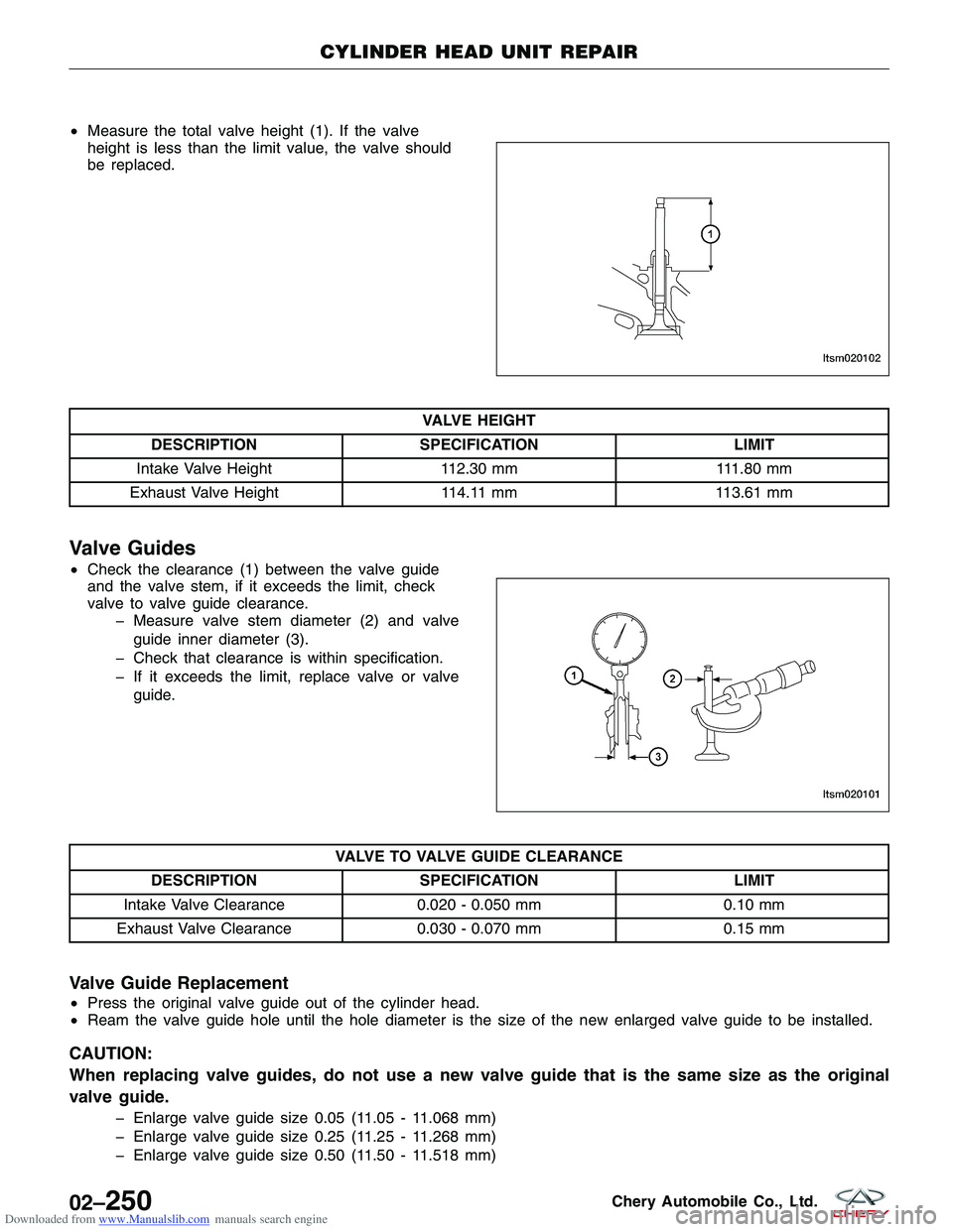
Downloaded from www.Manualslib.com manuals search engine •Measure the total valve height (1). If the valve
height is less than the limit value, the valve should
be replaced.
VALVE HEIGHT
DESCRIPTION SPECIFICATION LIMIT
Intake Valve Height 112.30 mm111.80 mm
Exhaust Valve Height 114.11 mm113.61 mm
Valve Guides
•Check the clearance (1) between the valve guide
and the valve stem, if it exceeds the limit, check
valve to valve guide clearance.
� Measure valve stem diameter (2) and valve
guide inner diameter (3).
� Check that clearance is within specification.
� If it exceeds the limit, replace valve or valve guide.
VALVE TO VALVE GUIDE CLEARANCE
DESCRIPTION SPECIFICATION LIMIT
Intake Valve Clearance 0.020 - 0.050 mm 0.10 mm
Exhaust Valve Clearance 0.030 - 0.070 mm 0.15 mm
Valve Guide Replacement
•Press the original valve guide out of the cylinder head.
• Ream the valve guide hole until the hole diameter is the size of the new enlarged valve guide to be installed.
CAUTION:
When replacing valve guides, do not use a new valve guide that is the same size as the original
valve guide.
� Enlarge valve guide size 0.05 (11.05 - 11.068 mm)
� Enlarge valve guide size 0.25 (11.25 - 11.268 mm)
� Enlarge valve guide size 0.50 (11.50 - 11.518 mm)
CYLINDER HEAD UNIT REPAIR
LTSM020102
LTSM020101
02–250Chery Automobile Co., Ltd.
Page 280 of 1903
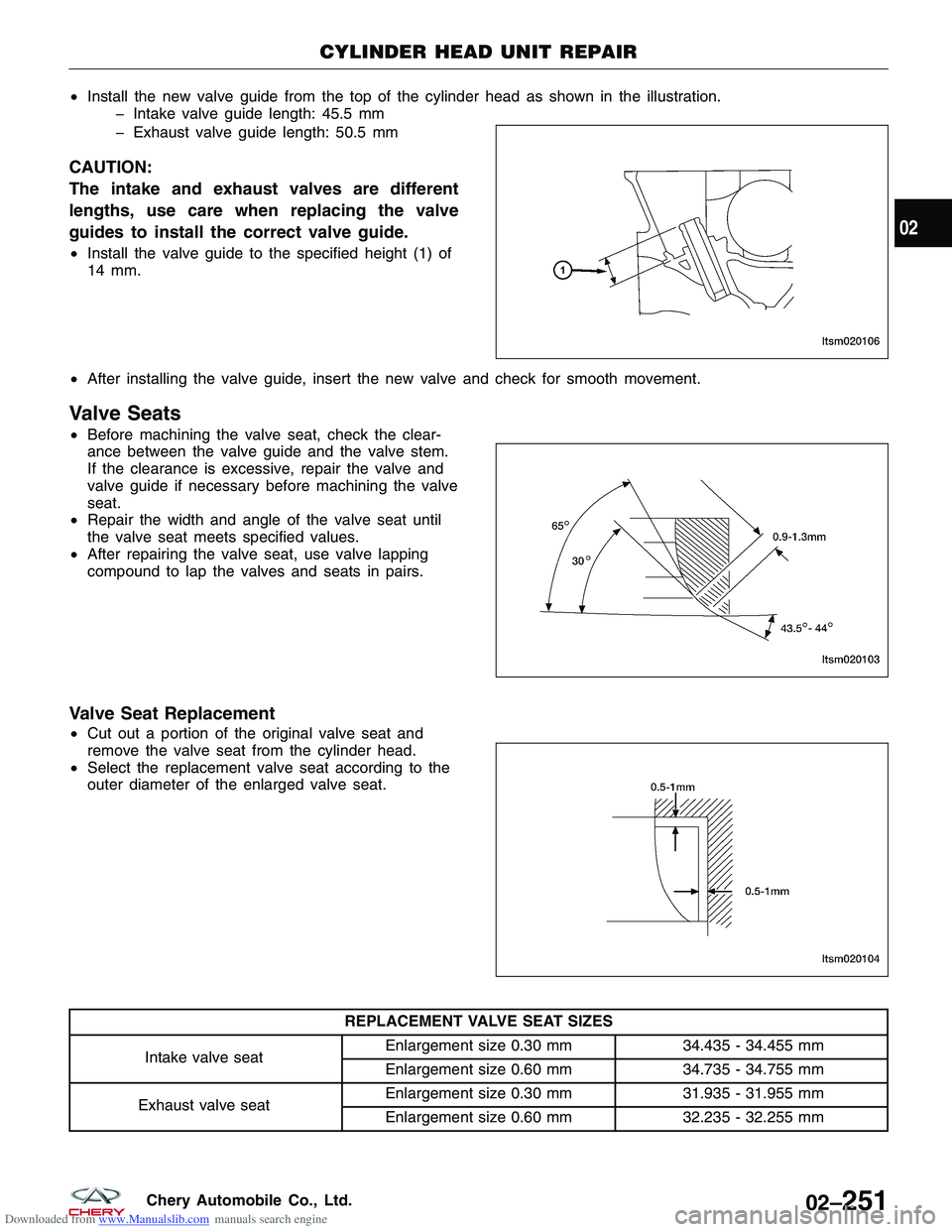
Downloaded from www.Manualslib.com manuals search engine •Install the new valve guide from the top of the cylinder head as shown in the illustration.
� Intake valve guide length: 45.5 mm
� Exhaust valve guide length: 50.5 mm
CAUTION:
The intake and exhaust valves are different
lengths, use care when replacing the valve
guides to install the correct valve guide.
•Install the valve guide to the specified height (1) of
14 mm.
• After installing the valve guide, insert the new valve and check for smooth movement.
Valve Seats
•Before machining the valve seat, check the clear-
ance between the valve guide and the valve stem.
If the clearance is excessive, repair the valve and
valve guide if necessary before machining the valve
seat.
• Repair the width and angle of the valve seat until
the valve seat meets specified values.
• After repairing the valve seat, use valve lapping
compound to lap the valves and seats in pairs.
Valve Seat Replacement
•Cut out a portion of the original valve seat and
remove the valve seat from the cylinder head.
• Select the replacement valve seat according to the
outer diameter of the enlarged valve seat.
REPLACEMENT VALVE SEAT SIZES
Intake valve seat Enlargement size 0.30 mm
34.435 - 34.455 mm
Enlargement size 0.60 mm 34.735 - 34.755 mm
Exhaust valve seat Enlargement size 0.30 mm
31.935 - 31.955 mm
Enlargement size 0.60 mm 32.235 - 32.255 mm
CYLINDER HEAD UNIT REPAIR
LTSM020106
LTSM020103
LTSM020104
02
02–251Chery Automobile Co., Ltd.