tow CHEVROLET CAMARO 1967 1.G Chassis User Guide
[x] Cancel search | Manufacturer: CHEVROLET, Model Year: 1967, Model line: CAMARO, Model: CHEVROLET CAMARO 1967 1.GPages: 659, PDF Size: 114.24 MB
Page 79 of 659
HEATER AND AIR CONDITIONING 1A-56
BLACK & RED
IGNITION—-y^****
SWITCH -"A
/
BLOWER LEAD—^^^
RESISTOR—-" \^<
ASM.
f'
i
'fu^^^^A^^^^^r"G^OUH£>
WIRE
^^
k4
^EVAPORATOR HARNESS
' EVAPORATOR & BLOWER ASM.
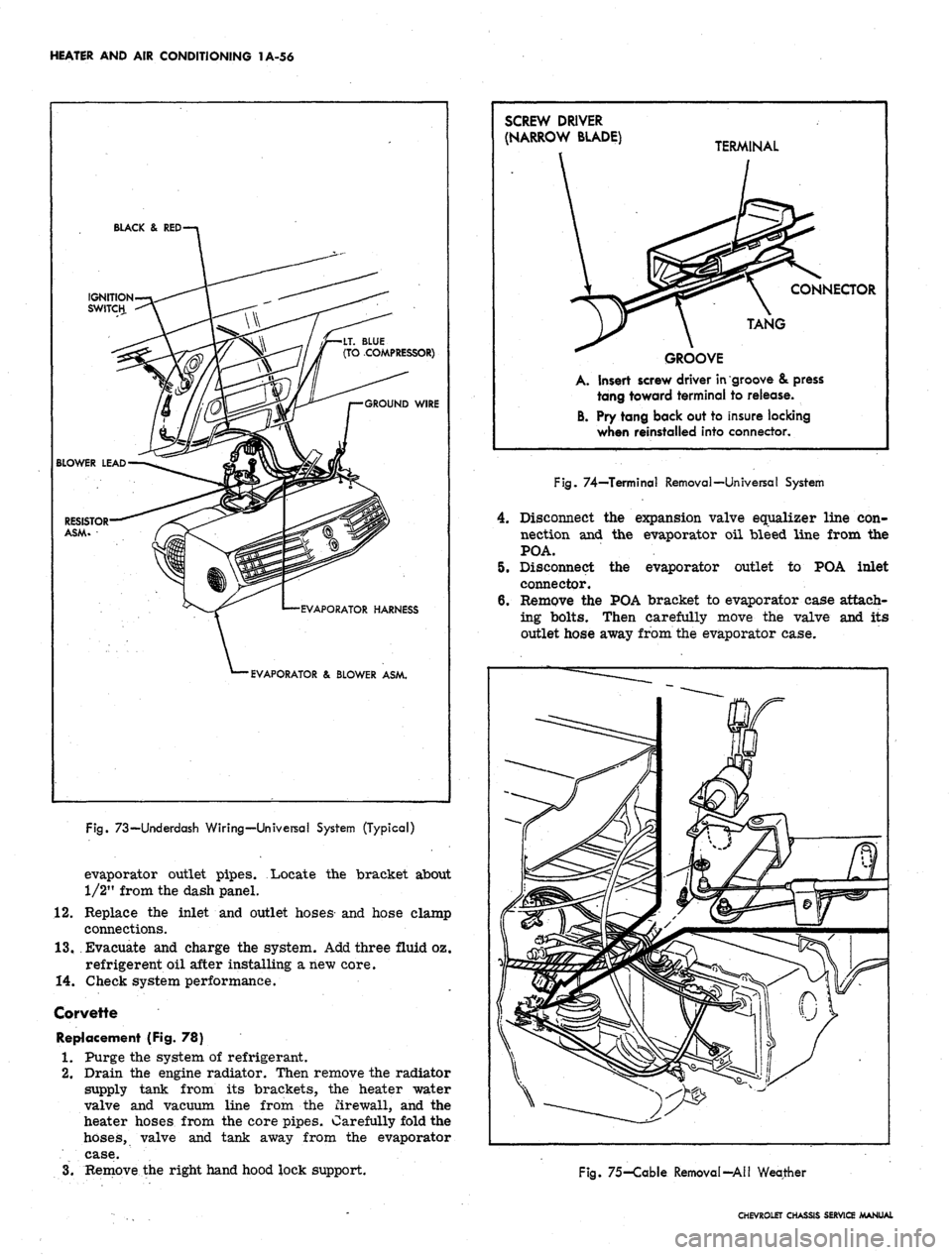
Fig.
73—Underdash Wiring—Universal System (Typical)
evaporator outlet pipes. Locate the bracket about
1/2" from the dash panel.
12.
Replace the inlet and outlet hoses and hose clamp
connections.
13.
Evacuate and charge the system. Add three fluid oz.
refrigerent oil after installing a new core.
14.
Check system performance.
Corvette
Replacement (Fig. 78)
1.
Purge the system of refrigerant.
2.
Drain the engine radiator. Then remove the radiator
supply tank from its brackets, the heater water
valve and vacuum line from the firewall, and the
heater hoses from the core pipes. Carefully fold the
hoses,
valve and tank away from the evaporator
case.
3.
Remove the right hand hood lock support.
SCREW DRIVER
(NARROW BLADE) T£
GROOVE
A. Insert screw driver in
tang toward terminal
B. Pry tang back out to
when reinstalled into
RMINAL
\ CONNECTOR
TANG
groove & press
to release.
insure locking
connector.
Fig.
74—Terminal Removal—Universal System
4.
Disconnect the expansion valve equalizer line con-
nection and the evaporator oil bleed line from the
POA.
5.
Disconnect the evaporator outlet to POA inlet
connector.
6. Remove the POA bracket to evaporator case attach-
ing bolts. Then carefully move the valve and its
outlet hose away from the evaporator case.
Fig.
75-Cable Removal-All Weather
CHEVROLET CHASSIS SERVICE MANUAL
Page 84 of 659
HEATER AND AIR CONDITIONING 1A-61
INSERT CAPILLARY
BETWEEN FINS AT
ARROW
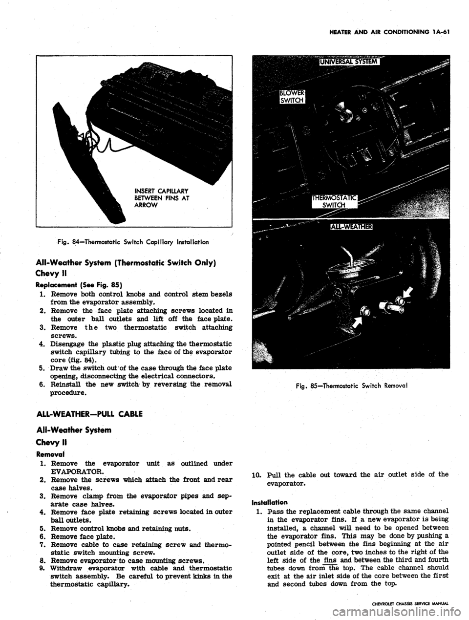
Fig.
84—Thermostatic Switch Capillary Installation
All-Weather System (Thermostatic Switch Only)
Chevy II
Replacement (See Fig. 85)
1.
Remove both control knobs and control stem bezels
from the evaporator assembly.
2.
Remove the face plate attaching screws located in
the outer ball outlets and lift off the face plate.
3.
Remove the two thermostatic switch attaching
screws.
4.
Disengage the plastic plug attaching the thermostatic
switch capillary tubing to the face of the evaporator
core (fig. 84).
5. Draw the switch out of the case through the face plate
opening, disconnecting the electrical connectors.
6. Reinstall the new switch by reversing the removal
procedure.
Fig.
85—Thermostatic Switch Removal
unit as outlined under
ALL-WEATHER-PULL CABLE
All-Weather System
Chevy II
Removal
1.
Remove the evaporator
EVAPORATOR.
2.
Remove the screws which attach the front and rear
case halves.
3.
Remove clamp from the evaporator pipes and sep-
arate case halves.
4.
Remove face plate retaining screws located in outer
ball outlets.
5. Remove control knobs and retaining nuts.
6. Remove face plate.
7. Remove cable to case retaining screw and thermo-
static switch mounting screw.
8. Remove evaporator to case mounting screws.
9. Withdraw evaporator with cable and thermostatic
switch assembly. Be careful to prevent kinks in the
thermostatic capillary.
10.
Pull the cable out toward the air outlet side of the
evaporator.
Installation
1.
Pass the replacement cable through the same channel
in the evaporator fins. If a new evaporator is being
installed, a channel will need to be opened between
the evaporator fins. This may be done by pushing a
pointed pencil between the fins beginning at the air
outlet side of the core, two inches to the right of the
left side of the fins and between the third and fourth
tubes down from the top. The cable channel should
exit at the air inlet side of the core between the first
and second tubes down from the top.
CHEVROLET CHASSIS SERVICE MANUAL
Page 86 of 659
HEATER AND AIR CONDITIONING 1A-63
Under Dash
7. Remove ash tray and retainer, and glove box.
8. Remove blower case to air inlet adapter bracket
retaining screw.
9. Remove screw attaching air distributor to firewall.
10.
Remove nuts retaining evaporator case to lower lip
of dash. Withdraw evaporator drain tubes.
11.
Lower complete heater - air conditioning assembly.
12.
Remove screw retaining blower case to air distrib-
utor and separate them.
13.
Remove blower to case attaching screws. Disconnect
motor wire and remove blower assembly.
14.
Remove blower from motor shaft.
Installation
1.
Assemble blower to motor shaft.
2.
Mount motor in blower case and connect wire.
3.
Assemble blower case to air distributor and install
retaining screw.
4.
Lift the complete assembly into place and install
attaching screws and nuts.
5. Replace ash tray retainer and tray and glove box.
6. Replace nuts (engine side of dash) on heater case
studs and connect heater hoses.
7. Replace evaporator pipe clamp and grommet.
8. Replace the refrigerant hoses.
9. Evacuate and charge the refrigeration system and
refill the cooling system.
10.
Check system performance.
Universal Blower Assembly
Removal
1.
Remove the universal unit from its dash mounts.
2.
Remove the cover plate and separate the upper and
lower case halves. Remove blower motor mounting
strap screw and swing strap outward.
3.
Remove blower assembly. Loosen the blower wheel
setscrews and remove the wheels from the motor
shaft. . ' .
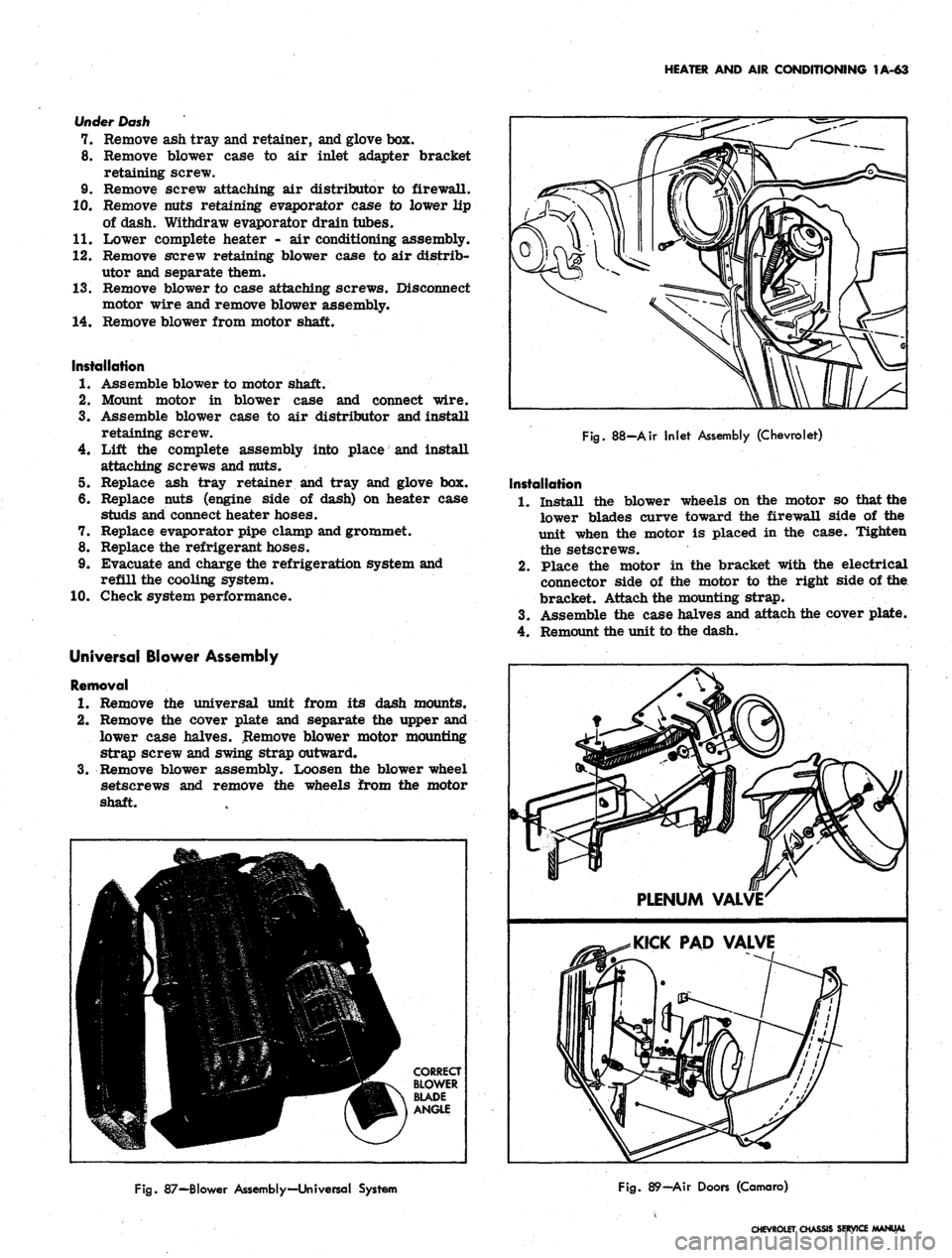
Fig.
88-Air Inlet Assembly (Chevrolet)
Installation
1.
Install the blower wheels on the motor so that the
lower blades curve toward the firewall side of the
unit when the motor is placed in the case. Tighten
the setscrews.
2.
Place the motor in the bracket with the electrical
connector side of the motor to the right side of the
bracket. Attach the mounting strap.
3.
Assemble the case halves and attach the cover plate.
4.
Remount the unit to the dash.
Fig.
87—Blower Assembly—Universal System
Fig.
89—Air Doors (Camaro)
CHEVROLET CHASSIS SERVICE
Page 112 of 659
CORVETTE BODY 1B-5
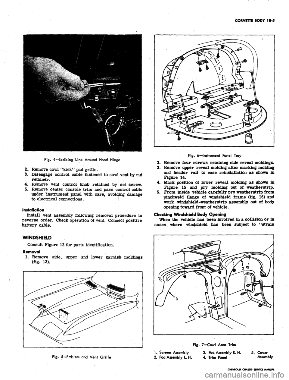
Fig.
4—Scribing
Line
Around
Hood
Hingje
2.
Remove cowl "kick" pad grille. |
3.
Disengage control cable fastened to cowl vent by nut
retainer. !
4.
Remove vent control knob retained by
|
set screw.
5. Remove center console trim and pass control cable
under instrument panel with care, avoiding damage
to electrical connections. j
Installation
Install vent assembly following removal procedure in
reverse order. Check operation of vent. Connect positive
battery cable.
Fig.
6—Instrument
Panel Tray
2.
Remove four screws retaining side reveal moldings.
3.
Remove upper reveal molding after marking molding
and header rail to ease reinstallation as shown in
Figure 14.
4.
Mark position of lower reveal molding as shown in
Figure 15 and pry molding out of weatherstrip.
5. From inside vehicle carefully pry weatherstrip from
pinchweld flange of windshield frame (fig. 16) and
work windshield-weatherstrip assembly out of body
opening toward front of vehicle.
Checking Windshield Body Opening
When the vehicle has been involved in a collision or in
cases where windshield has been subject to "strain
WINDSHIELD
Consult Figure 12 for parts identification.
Removal
1.
Remove side, upper and lower garnish moldings
(fig. 13).
Fig.
5—Emblem dnd
Vent Grille
1.
Screen
Assembly
2.
Pad
Assembly
L H.
Fig.
7-Cowl
Area Trim
3.
Pad
Assembly
R. H. 5.
Cover
4.
Trim Panel
Assembly
CHEVROLET CHASSIS SERVICE MANUAL
Page 113 of 659
CORVETTE BODY
1B-6
ASH TRAY
SET SCREW
(PART
OF
KNOB)
TENSION
ADJUSTING
SCREWS
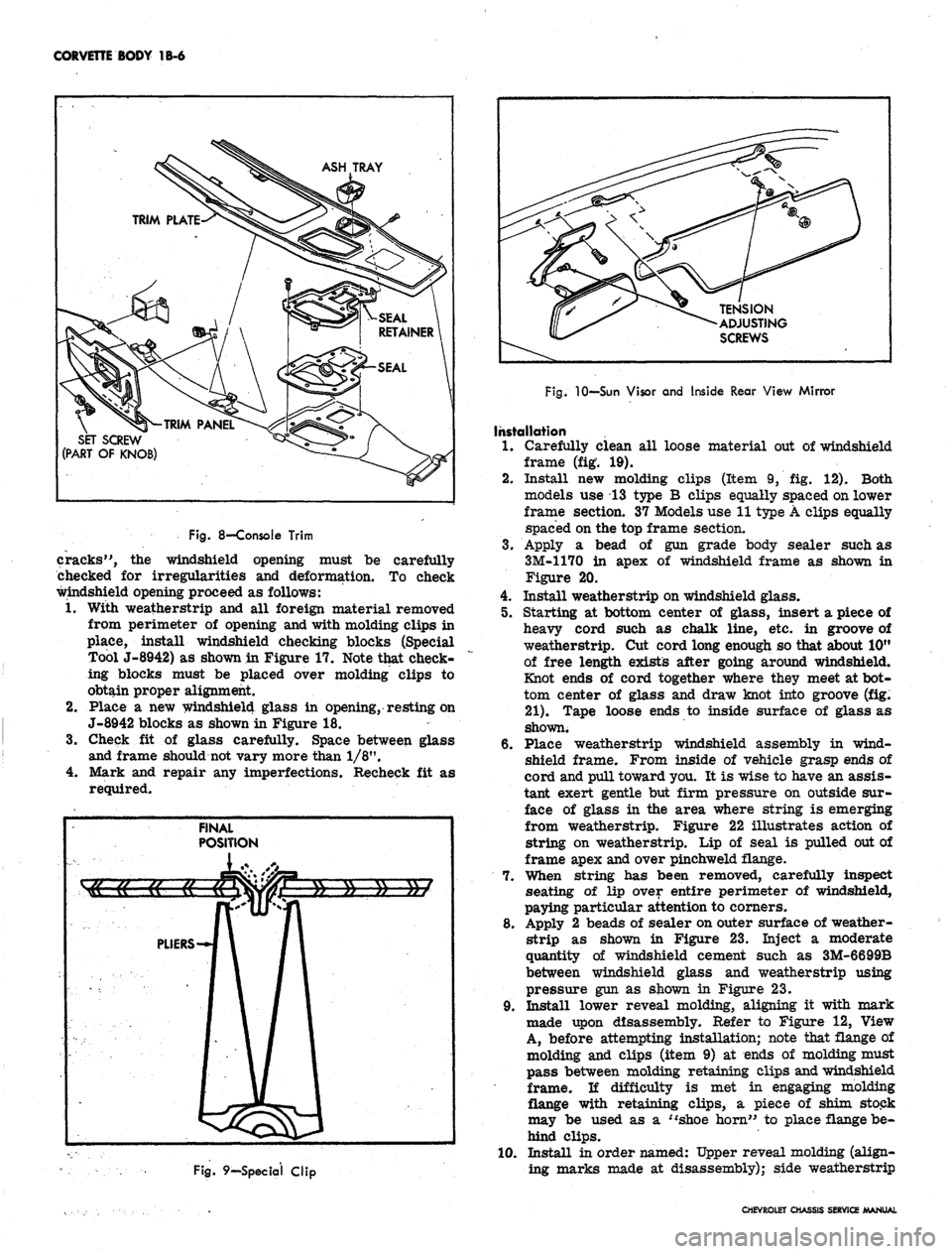
Fig.
8—Console Trim
cracks",
the
windshield opening must
be
carefully
checked
for
irregularities
and
deformation.
To
check
windshield opening proceed
as
follows:
1.
With weatherstrip
and all
foreign material removed
from perimeter
of
opening and with molding clips
in
place, install windshield checking blocks (Special
Tool J-8942)
as
shown in Figure 17. Note that check-
ing blocks must
be
placed over molding clips
to
obtain proper alignment.
2.
Place
a new
windshield glass
in
opening, resting on
J-8942 blocks
as
shown in Figure
18.
3.
Check
fit of
glass carefully. Space between glass
and frame should not vary more than 1/8".
4.
Mark
and
repair
any
imperfections. Recheck
fit as
required.
Fig.
9—Special Clip
Fig.
10—Sun Visor and Inside Rear View Mirror
Installation
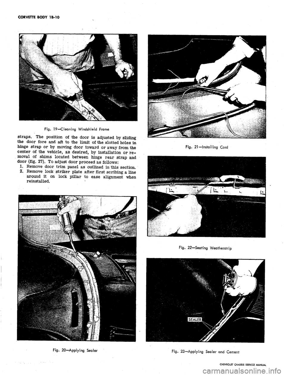
1.
Carefully clean
all
loose material
out of
windshield
frame
(fig. 19).
2.
Install
new
molding clips (Item
9, fig. 12).
Both
models
use 13
type
B
clips equally spaced on lower
frame section.
37
Models use 11 type A clips equally
spaced on the top frame section.
3.
Apply
a
bead
of gun
grade body sealer such
as
3M-1170
in
apex
of
windshield frame
as
shown
in
Figure
20.
4.
Install weatherstrip on windshield glass.
5. Starting
at
bottom center
of
glass, insert
a
piece
of
heavy cord such
as
chalk line,
etc. in
groove
of
weatherstrip.
Cut
cord long enough so that about 10"
of free length exists after going around windshield.
Knot ends
of
cord together where they meet at bot-
tom center
of
glass
and
draw knot into groove
(fig.
21).
Tape loose ends
to
inside surface
of
glass
as
shown.
6. Place weatherstrip windshield assembly
in
wind-
shield frame. From inside
of
vehicle grasp ends
of
cord and pull toward you.
It is
wise to have an assis-
tant exert gentle
but
firm pressure
on
outside sur-
face
of
glass
in the
area where string
is
emerging
from weatherstrip. Figure
22
illustrates action
of
string
on
weatherstrip.
Lip of
seal
is
pulled out of
frame apex and over pinchweld flange.
7. When string
has
been removed, carefully inspect
seating
of lip
over entire perimeter
of
windshield,
paying particular attention to corners.
8. Apply
2
beads
of
sealer on outer surface
of
weather-
strip
as
shown
in
Figure
23.
Inject
a
moderate
quantity
of
windshield cement such
as
3M-6699B
between windshield glass
and
weatherstrip using
pressure gun
as
shown
in
Figure
23.
9. Install lower reveal molding, aligning
it
with mark
made upon disassembly. Refer
to
Figure
12,
View
A, before attempting installation; note that flange
of
molding
and
clips (item
9) at
ends
of
molding must
pass between molding retaining clips and windshield
frame.
li
difficulty
is met in
engaging molding
flange with retaining clips,
a
piece
of
shim stock
may
be
used
as a
"shoe horn"
to
place flange be-
hind clips.
10.
Install
in
order named: Upper reveal molding (align-
ing marks made
at
disassembly); side weatherstrip
CHEVROLET CHASSIS SERVICE MANUAL
Page 117 of 659
CORVETTE BODY IB-10
Fig.
19—Cleaning Windshield Frame
straps.
The position of the door is adjusted by sliding
the door fore and aft to the limit of the slotted holes in
hinge strap or by moving door toward or away from the
center of the vehicle, as desired, by installation or re-
moval of shims located between hinge rear strap and
door (fig. 27). To adjust door proceed as follows:
1.
Remove door trim panel as outlined in this section.
2.
Remove lock striker plate after first scribing a line
around it on lock pillar to ease alignment when
reinstalled. '
Fig. 21-Installing Cord
Fig. 22—Seating Weatherstrip
Fig. 20—Applying Sealer
Fig. 23—Applying Sealer and Cement
CHEVROLET CHASSIS SERVICE MANUAL
Page 124 of 659
CORVETTE BODY 1B-17
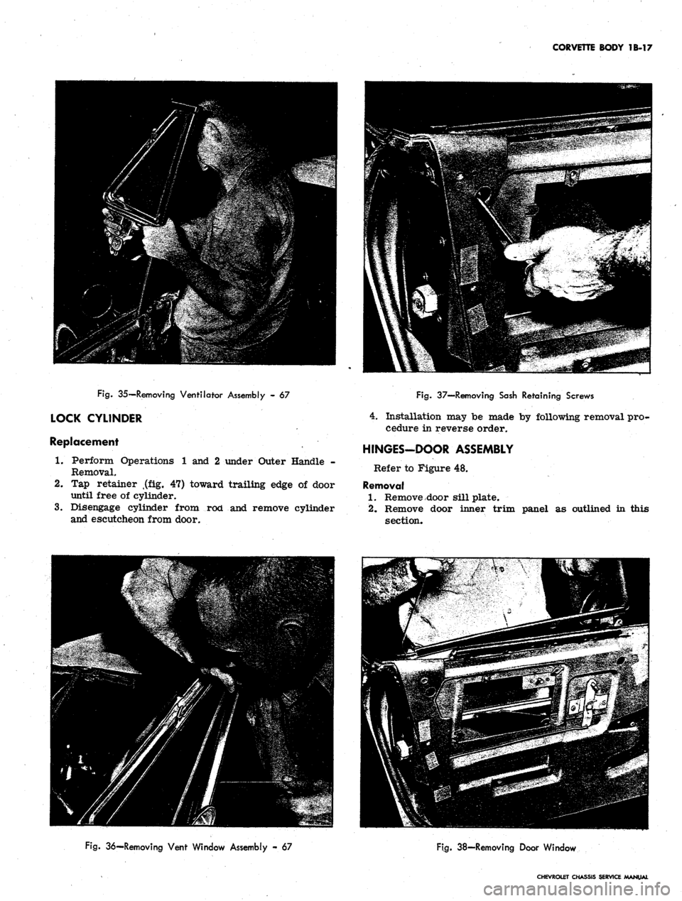
Fig.
35—Removing Ventilator Assembly - 67
LOCK CYLINDER
Replacement
1.
Perform Operations 1 and 2 under Outer Handle -
Removal.
2.
Tap retainer t(flLg. 47) toward trailing edge of door
until free of cylinder.
3.
Disengage cylinder from rod and remove cylinder
and escutcheon from door.
Fig.
37—Removing Sash Retaining Screws
4.
Installation may be made by following removal pro-
cedure in reverse order.
HINGES-DOOR ASSEMBLY
Refer to Figure 48.
Removal
1.
Remove door sill plate.
2.
Remove door inner trim panel as outlined in this
section.
Fig.
36—Removing Vent Window Assembly - 67
Fig.
38-Removing Door Window
CHEVROLET CHASSIS SERVICE /MANUAL
Page 136 of 659
CORVETTE BODY 1B-29
CUSHION
CUSHION ASNi.^ty** ACCESS
#2 BODY BRACKET
( 67 ONLY)
SHIM
( 37 POSITION).
CUSHION ASM.
( 37)
SHIM
( 67 POSITION)
CUSHION
( 37 ONLY)
#1 BODY BRACKET
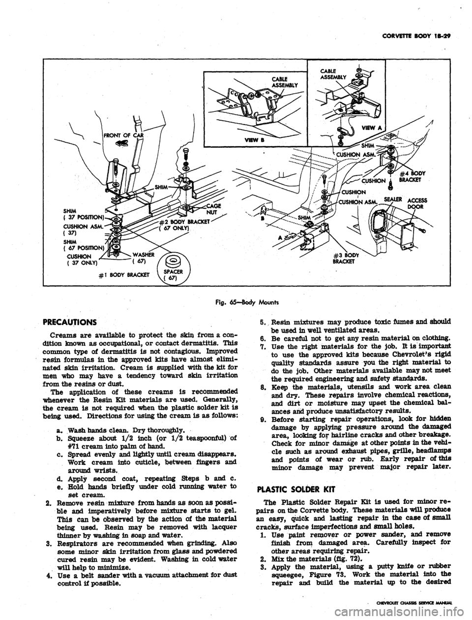
Fig.
65—Body Mounts
PRECAUTIONS
Creams are available to protect the skin from a con-
dition known as occupational, or contact dermatitis. This
common type of dermatitis is not contagious. Improved
resin formulas in the approved kits have almost elimi-
nated skin irritation. Cream is supplied with the kit for
men who may have a tendency toward skin irritation
from the resins or dust.
The application of these creams is recommended
whenever the Resin Kit materials are used. Generally,
the cream is not required when the plastic solder kit is
being used. Directions for using the cream is as follows:
a. Wash hands clean. Dry thoroughly.
b.
Squeeze about 1/2 inch (or 1/2 teaspoonful) of
#71 cream into palm of hand.
c. Spread evenly and lightly until cream disappears.
Work cream into cuticle, between fingers and
around wrists.
d. Apply second coat, repeating Steps b and c.
e. Hold hands briefly under cold running water to
set cream.
2.
Remove resin mixture from hands as soon as possi-
ble and imperatively before mixture starts to gel.
This can be observed by the action of the material
being used. Resin may be removed with lacquer
thinner by washing in soap and water.
3.
Respirators are recommended when grinding. Also
some minor skin irritation from glass and powdered
cured resin may be evident. Washing in cold water
will help to minimize.
4.
Use a belt sander with a vacuum attachment for dust
control if possible.
5. Resin mixtures may produce toxic fumes and should
be used in well ventilated areas.
6. Be careful not to get any resin material on clothing.
7. Use the right materials for the job. It is important
to use the approved kits because Chevrolet's rigid
quality standards assure you the right material to
do the job. Other materials available may not meet
the required engineering and safety standards.
8. Keep the materials, utensils and work area clean
and dry. These repairs involve chemical reactions,
and dirt or moisture may upset the chemical bal-
ances and produce unsatisfactory results.
9. Before starting repair operations, look for hidden
damage by applying pressure around the damaged
area, looking for hairline cracks and other breakage.
Check for minor damage at other points in the vehi-
cle such as around exhaust pipes, grille, headlamps
and points of wear or rub. Early repair of this
minor damage may prevent major repair later.
PLASTIC SOLDER
KIT
The Plastic Solder Repair Kit is used for minor re-
pairs on the Corvette body. These materials will produce
an easy, quick and lasting repair in the case of small
cracks, surface imperfections and small holes.
1.
Use paint remover or power sander, and remove
finish from damaged area. Carefully inspect for
other areas requiring repair.
2.
Mix the materials (fig. 72).
3.
Apply the material, using a putty knife or rubber
squeegee, Figure 73. Work the material into the
repair and build the material up to the desired
CHEVROLET CHASSIS SERVICE
Page 148 of 659
CORVETTE BODY 1B-41
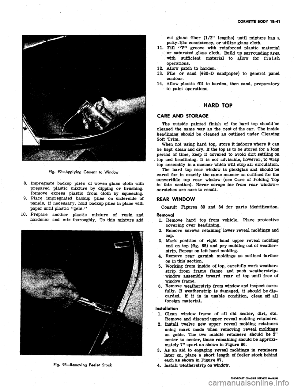
Fig.
92—Applying Cement to Window
8. Impregnate backup plies of woven glass cloth with
prepared plastic mixture by dipping or brushing.
Remove excess plastic from cloth by squeezing.
9. Place impregnated backup plies on underside of
panels. If necessary, hold backup plies in place with
paper until plastic "gels."
10.
Prepare another plastic mixture of resin and
hardener and mix thoroughly. To this mixture add
Fig.
93—Removing Feeler Stock
cut glass fiber (1/2" lengths) until mixture has a
putty-like consistency, or utilize glass cloth.
11.
Fill "V" groove with reinforced plastic material
or saturated glass cloth. Build up surrounding area
with sufficient material to allow for finish
operations.
12.
Allow patch to harden.
1.3. File or sand (#80-D sandpaper) to general panel
contour.
14.
Allow plastic fill to harden, then sand, preparatory
to paint operations.
HARD TOP
CARE AND STORAGE
The outside painted finish of the hard top should be
cleaned the same way as the rest of the car. The inside
headlining should be cleaned as outlined under Cleaning
Soft Trim.
When not using hard top, store it indoors where it can
be kept clean and dry. If the top is to be stored for a long
period of time, keep it covered to avoid dirt settling on
top and headlining. It is not advisable, however, to wrap
top assembly in a manner which will stop air circulation.
The hard top rear window is plexiglas and should be
cared for in exactly the same manner as outlined for the
convertible top rear window (see Care of Folding Top
in this section). Never scrape ice from rear window-
scratches are sure to result.
REAR WINDOW
Consult Figures 83 and 84 for parts identification.
Removal
1.
Remove hard top from vehicle. Place protective
covering over headlining.
2.
Remove screws retaining lower reveal moldings and
cap.
3.
Mark position of right hand upper reveal molding
end on top (fig. 85) and pry molding out of weather-
strip.
Repeat on left hand molding.
4.
Remove rear garnish moldings as outlined farther
on in this section.
5. Working from inside of top, carefully work weather-
strip from frame flange and push weatherstrip-
window assembly toward rear of top until free of
window frame.
6. Remove weatherstrip from window and inspect care-
fully. If weatherstrip is damaged, it should be dis-
carded. If it is in usable condition, clean off all
foreign material.
Installation
1.
Clean window frame of all old sealer, dirt, etc.
Remove and discard upper reveal molding retainers.
2.
Install twelve new upper reveal molding retainers
using mark made when removing reveal moldings
as guide. The two middle retainers should be 2"
center to center, those remaining should be approxi-
mately 7" apart as shown in Figure 86.
3.
As an aid to engaging reveal moldings in retainers
later on, place a short length of feeler stock behind
each as shown in Figure 87.
4.
Install weatherstrip on window.
CHEVROLET CHASSIS SERVICE MANUAL
Page 149 of 659
CORVETTE BODY 1B-42
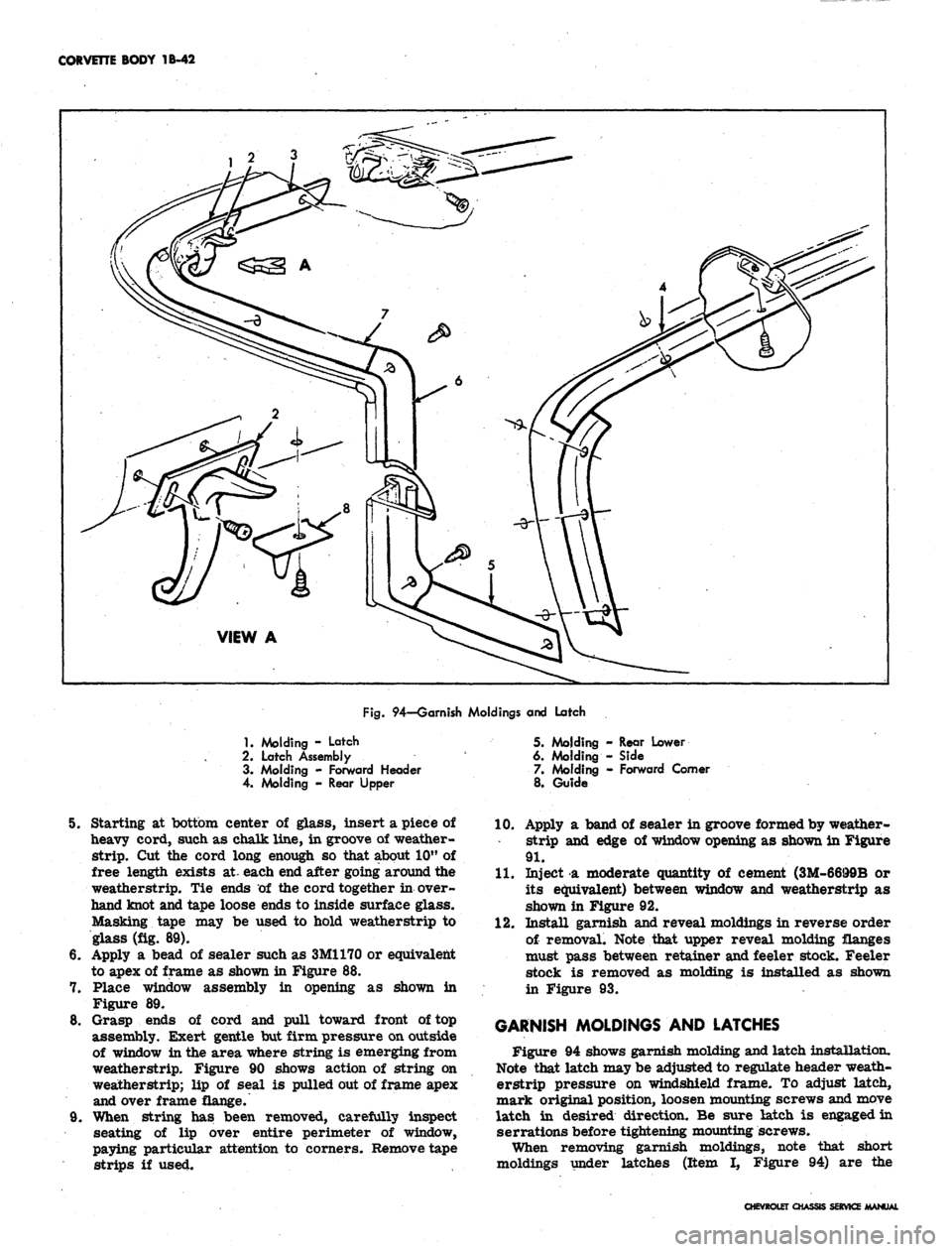
Fig.
94—Garnish Moldings and Latch
1.
Molding - Latch
2.
Latch Assembly
3. Molding - Forward Header
4. Molding - Rear Upper
5. Molding - Rear Lower
6. Molding - Side
7. Molding - Forward Comer
8. Guide
8.
9,
Starting at bottom center of glass, insert a piece of
heavy cord, such as chalk line, in groove of weather-
strip.
Cut the cord long enough so that about 10" of
free length exists at- each end after going around the
weatherstrip. Tie ends of the cord together in over-
hand knot and tape loose ends to inside surface glass.
Masking tape may be used to hold weatherstrip to
glass (fig. 89).
Apply a bead of sealer such as 3M1170 or equivalent
to apex of frame as shown in Figure 88.
Place window assembly in opening as shown in
Figure 89.
Grasp ends of cord and pull toward front of top
assembly. Exert gentle but firm pressure on outside
of window in the area where string is emerging from
weatherstrip. Figure 90 shows action of string on
weatherstrip; lip of seal is pulled out of frame apex
and over frame flange.
When string has been removed, carefully inspect
seating of lip over entire perimeter of window,
paying particular attention to corners. Remove tape
strips if used.
10.
Apply a band of sealer in groove formed by weather-
strip and edge of window opening as shown in Figure
91.
11.
Inject a moderate quantity of cement (3M-6699B or
its equivalent) between window and weatherstrip as
shown in Figure 92.
12.
Install garnish and reveal moldings in reverse order
of removal. Note that upper reveal molding flanges
must pass between retainer and feeler stock. Feeler
stock is removed as molding is installed as shown
in Figure 93.
GARNISH MOLDINGS AND LATCHES
Figure 94 shows garnish molding and latch installation.
Note that latch may be adjusted to regulate header weath-
erstrip pressure on windshield frame. To adjust latch,
mark original position, loosen mounting screws and move
latch in desired direction. Be sure latch is engaged in
serrations before tightening mounting screws.
When removing garnish moldings, note that short
moldings under latches (Item I, Figure 94) are the
CHEVROLET CHASSIS SERVICE MANUAL