tow CHEVROLET CAMARO 1967 1.G Chassis Owner's Manual
[x] Cancel search | Manufacturer: CHEVROLET, Model Year: 1967, Model line: CAMARO, Model: CHEVROLET CAMARO 1967 1.GPages: 659, PDF Size: 114.24 MB
Page 153 of 659
CORVETTE BODY 1B-46
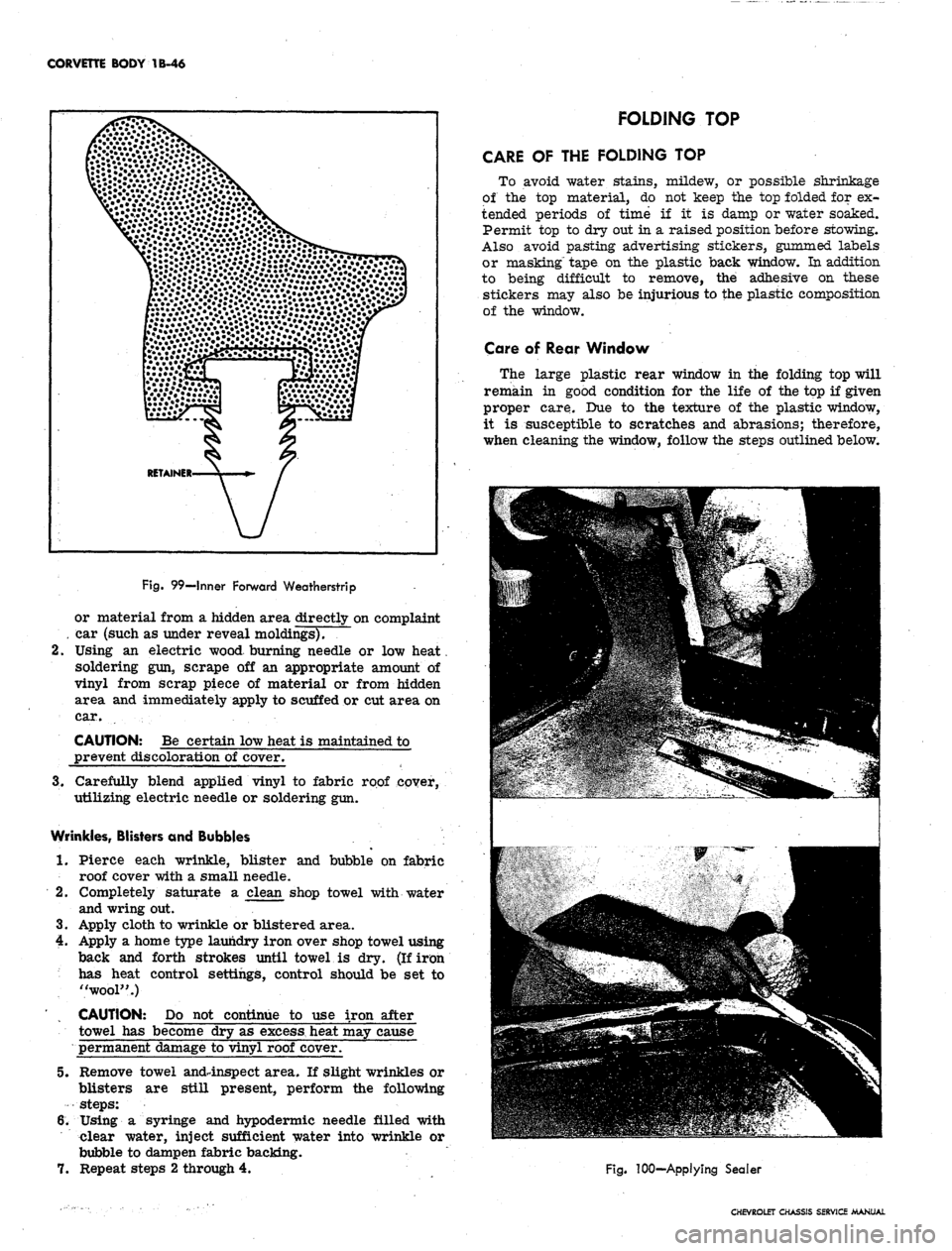
Fig.
99—Inner Forward Weatherstrip
or material from a hidden area directly on complaint
. car (such as under reveal moldings).
2.
Using an electric wood burning needle or low heat.
soldering gun, scrape off an appropriate amount of
vinyl from scrap piece of material or from hidden
area and immediately apply to scuffed or cut area on
car.
CAUTION: Be certain low heat is maintained to
prevent discoloration of cover.
3.
Carefully blend applied vinyl to fabric roof cover,
utilizing electric needle or soldering gun.
Wrinkles, Blisters and Bubbles
1.
Pierce each wrinkle, blister and bubble on fabric
roof cover with a small needle.
2.
Completely saturate a clean shop towel with water
and wring out.
3.
Apply cloth to wrinkle or blistered area.
4.
Apply a home type laundry iron over shop towel using
back and forth strokes until towel is dry. (If iron
has heat control settings, control should be set to
"wool".)
CAUTION: Do not continue to use iron after
towel has become dry as
excess,
heat may cause
permanent damage to vinyl roof cover.
5.
Remove towel and4nspect area. If slight wrinkles or
blisters are still present, perform the following
steps:
6. Using a syringe and hypodermic needle filled with
clear water, inject sufficient water into wrinkle or
bubble to dampen fabric backing.
7.
Repeat steps 2 through 4.
FOLDING TOP
CARE OF THE FOLDING TOP
To avoid water stains, mildew, or possible shrinkage
of the top material, do not keep the top folded for ex-
tended periods of time if it is damp or water soaked.
Permit top to dry out in a raised position before stowing.
Also avoid pasting advertising stickers, gummed labels
or masking" tape on the plastic back window. In addition
to being difficult to remove, the adhesive on these
stickers may also be injurious to the plastic composition
of the window.
Care of Rear Window
The large plastic rear window in the folding top will
remain in good condition for the life of the top if given
proper care. Due to the texture of the plastic window,
it is susceptible to scratches and abrasions; therefore,
when cleaning the window, follow the steps outlined below.
Fig.
100-Applying Sealer
CHEVROLET CHASSIS SERVICE MANUAL
Page 175 of 659
FRONT SUSPENSION 3-11
Chevy II (Fig. 14)
Removal
1.
While vehicle weight is still on front wheels, position
support between upper control arm and frame side
rail (fig. 15).
NOTE: Bight side control arm support bracket
is illustrated in Figure 15. For left side, angled
support should be welded to reverse side of
plate.
2.
Raise vehicle and remove wheel and tire.
3.
Disconnect lower shock absorber mounting nuts, lock
washers and rubber washers from lower spring seat.
4.
Remove shock absorber upper mounting bracket
bolts.
Lift bracket and shock absorber assembly
from vehicle (fig. 16).
5.
Remove shock absorber from upper mounting bracket
and remove rubber bushings and washers.
Installation
1.
Assemble upper washer and rubber bushing to shock
absorber rod (refer to Figure 14).
2.
Assemble upper mounting bracket, bushing, washer
and nut to rod. Torque according to Specifications at
the end of this book.
3.
Install rubber washers to shock absorber lower seat
studs and insert shock absorber and upper bracket
assembly into shock absorber access hole, and posi-
tion to the lower spring seat. Install washers, nuts
and torque according to Specifications at the end of
this book.
NOTE: Shock absorber seat upper washers
must correctly pilot into spring seat.
4.
Install upper mounting bracket to spring tower and
torque nuts according to Specifications at the end of
this book.
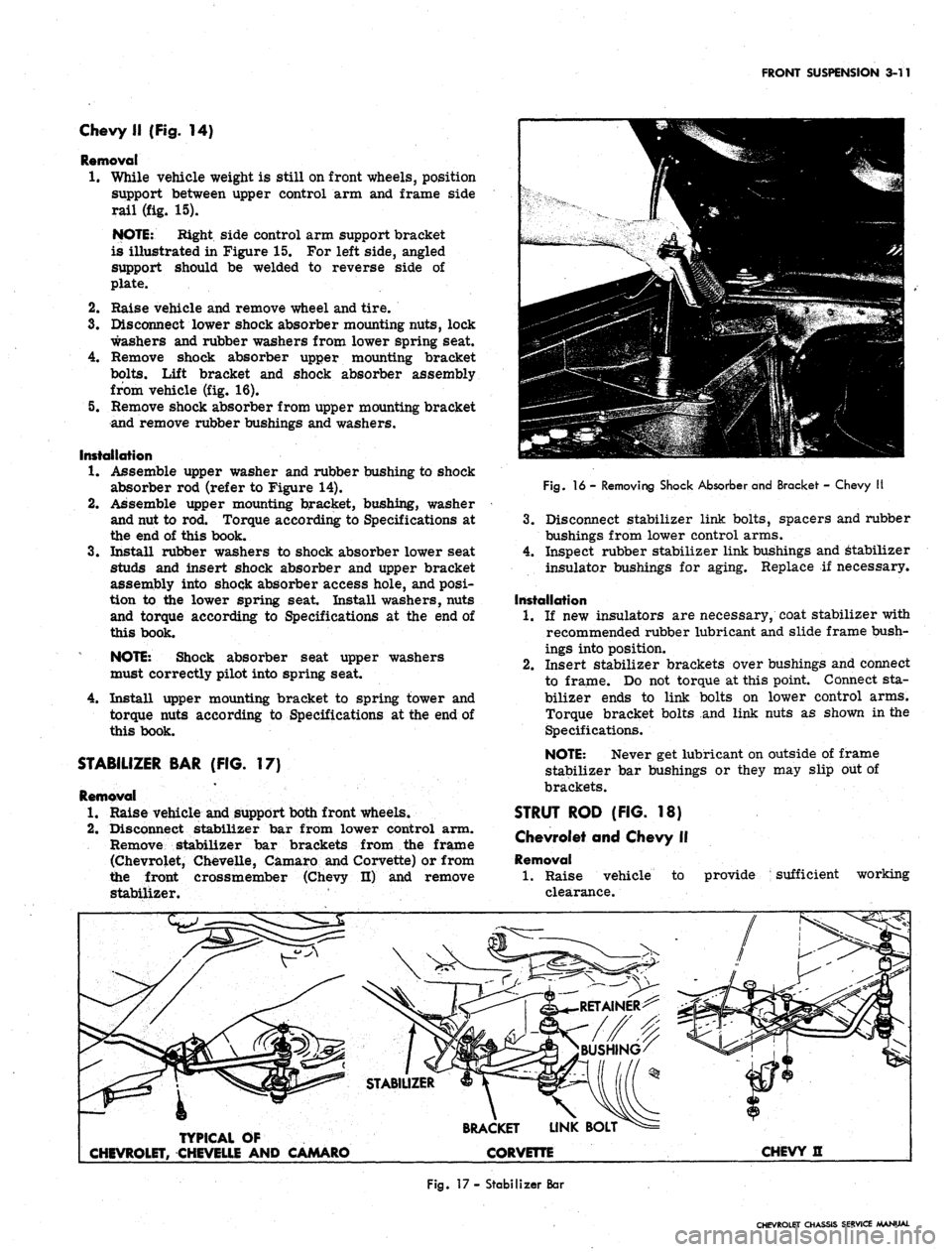
STABILIZER BAR (FIG. 17)
Removal
1.
Raise vehicle and support both front wheels.
2.
Disconnect stabilizer bar from lower control arm.
Remove stabilizer bar brackets from the frame
(Chevrolet, Chevelle, Camaro and Corvette) or from
the front crossmember (Chevy n) and remove
stabilizer.
Fig.
16 - Removing Shock Absorber and Bracket - Chevy II
3.
Disconnect stabilizer link bolts, spacers and rubber
bushings from lower control arms.
4.
Inspect rubber stabilizer link bushings and Stabilizer
insulator bushings for aging. Replace if necessary.
Installation
1.
If new insulators
are necessary, coat stabilizer with
recommended rubber lubricant and slide frame bush-
ings into position.
2.
Insert stabilizer brackets over bushings and connect
to frame. Do not torque at this point. Connect sta-
bilizer ends to link bolts on lower control arms.
Torque bracket bolts and link nuts as shown in the
Specifications.
NOTE: Never get lubricant on outside of frame
stabilizer bar bushings or they may slip out of
brackets.
STRUT ROD (FIG. 18)
Chevrolet and Chevy II
Removal
1.
Raise vehicle to
clearance.
provide sufficient working
TYPICAL OF
CHEVROLET, CHEVELLE AND CAMARO
BRACKET LINK BOLT
CORVETTE
CHEVY H
Fig.
17- Stabilizer Bar
CHEVROLET CHASSIS SERVICE MANUAL
Page 177 of 659
FRONT SUSPENSION ,3-13
6. Carefully lower the inner end of the control arm.
Tension on the spring will be removed before the
spring can be removed from the vehicle.
7.
Remove the spring.
Installation
1.
With the suspension set up as in Step 2 of the disas-
sembly procedure, insert a block of wood between the
upper control arm and the spring tower to keep the
arm up out of the way.
2.
Set the spring in place on the crossmember after
checking on proper positioning necessary.
3.
Install the steel bar and wood block as shown in Fig-
ure 20 and lift the control arm up until the inner
pivot cam bolt can be installed. ,
4.
Install the outer cam and loosely install the lock
washer and nut
5.
Set the cam bolt on the mark scribed during the re-
moval procedure and hold in this position while tight-
ening the nut (See specifications at the end of this
book).
6. Replace the strut rod to lower control arm nuts,
bolts and lock washers, the stabilizer bar link, the
shock absorber, the tie rod end, and the wheel and
tire.
7.
Lower vehicle to floor and install the shock absorber
upper stem retaining nut retainer and grommet.
8. Check the camber adjustment.
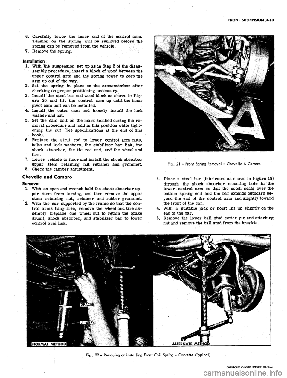
Chevelle and Camaro
Removal
1.
With an open end wrench hold the shock absorber up-
per stem from turning, and then, remove the upper
stem retaining nut, retainer and rubber grommet.
2.
With the car supported by the frame so that the con-
trol arms hang free, remove the wheel and tire as-
sembly (replace one wheel nut to retain the brake
drum),
shock absorber, and stabilizer bar to lower
control arm link.
4.
5.
Fig.
21 - Front Spring Removal - Chevelle & Camaro
Place a steel bar (fabricated as shown in Figure 19)
through the shock absorber mounting hole in the
lower control arm so that the notch seats over the
bottom spring coil and the bar extends outboard be-
yond the end of the control arm and slightly toward
the front of the car.
With a suitable jack or hoist lift up slightly on the
end of the bar.
Remove the lower ball stud cotter pin and attaching
nut and remove the ball stud from the knuckle.
ALTERNATE METHOD
Fig.
22 - Removing or Installing Front Coil Spring - Corvette (Typical)
CHEVROLET CHASSIS SERVICE MANUAL
Page 179 of 659
FRONT SUSPENSION 3-15
4.
Insert Spring Compressor J-
6874-
4-
5 with Adapters
J-6874-8-9 into upp^r spring tower so that lower
MU"
bolt fits into shock absorber mounting holes in
spring seat (fig. 23). Secure the two lower studs to
the spring seat with nuts.
5.
Fit the tool upper pilot to top of spring and compress
spring by tightening upper nut (fig. 24). Compress
spring until screw is bottomed out.
6. Remove lower spring seat retaining nuts, lift spring
and seat assembly from control arm and guide it
down and out through fender skirt (fig. 25).
Spring Seat Replacement (Fig. 26)
1.
Release spring tension and disconnect spring com-
pressor from spring seat.
2.
Install new spring seat to spring compressor.
Installation
1.
If spring is to be replaced, install new spring into
tool and compress spring until screw is bottomed
out.
NOTE: Spring coil ends must be against spring
stops in upper and lower seats.
2.
Lift spring and tool assembly into place and position
so that the upper spring stop is inboard.
NOTE: Locating tab on upper spring seat may
be flattened before reinstalling spring.
3.
Install lower spring seat to control arm and torque
nuts as shown in the Specifications.
4.
Loosen spring compressor until spring is properly
seated in upper spring tower and remove.
5.
Install shock abosrber as outlined under Shock Ab-
sorber—Installation in this section.
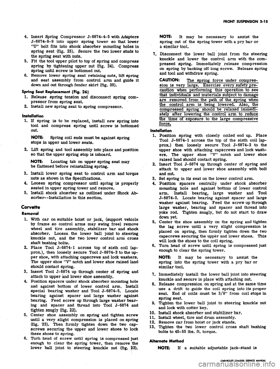
Corvette
Removal
1.
With car on suitable hoist or jack, (support vehicle
by frame so control arms may swing free) remove
wheel and tire assembly, stabilizer bar and shock
absorber. Loosen the lower ball joint to steering
knuckle nut, and the' two lower control arm cross
shaft bushing bolts.
2.
Place Tool J-6874-1 across top of sixth coil (ap-
prox.),
then loosely secure Tool J-6874-2 to the up-
per shoe, with attaching capscrews and lock washers.
The upper shoe "V" notch and lower shoe raised land
should contact spring.
3.
Insert Tool J-6874 up through center of spring and
attach to upper and lower shoe assembly.
4.
Position spacers under shock absorber mounting hole
and against bottom of lower control arm. Install
special bearing washer and Tool J-6874-5. Locate
bearing against spacer and large washer against
bearing. Feed screw up through large washer bear-
ing and spacer and thread into Tool J-6874 and
tighten snugly (fig. 22).
5.
Center shoe assembly on spring and tighten screw
until a very slight compression is placed on spring
(fig. '22). Then firmly tighten down the two cap-
screws securing the upper and lower shoes to lock
these shoes to spring.
6. Turn head of screw until spring is compressed just
enough to clear the spring tower, then remove the
lower ball joint to steering knuckle nut (fig. 22).
NOTE: It may be necessary to assist the
spring out of the spring tower with a pry bar or
a similar tool.
7.
Disconnect the lower ball joint from the steering
knuckle and lower the control arm with the com-
pressed spring. Immediately release compression
on spring by backing off long screw. Release spring
and tool and withdraw spring.
CAUTION: The spring force under compres-
sion is very large. Exercise every safety pre-
caution when performing this operation to see
that individuals and materials subject to damage
are removed from the path of the spring when
the control arm is being lowered. Also, the
compressed spring
be relaxed immedi-
ately after lowering the control arm to reduce
the time of exposure to the large compressive
force.
Installation
1.
Position spring with closely coiled end up. Place
Tool J-6874-1 across the top of the sixth coil (ap-
prox.) then loosely secure Tool J-6874-2 to the
upper shoe with attaching capscrews and lock wash-
ers.
The upper shoe MV" notch and lower shoe
raised land should contact spring.
2.
Insert Tool J-6874 up through center of spring and
attach to upper and lower shoe assembly with bolt
and nut.
3.
Set spring in its seat on the lower control arm.
4.
Position spacers centrally under shock absorber
mounting hole and against bottom of lower control
arm. Install bearing, large washer and Tool
J-6874-5.
Locate bearing against spacer and large
washer against bearing. Feed the screw up through
large washer, bearing and spacer and thread into
yoke rod. Tighten snugly, but do not start to draw
down yet
5.
Center the shoe assembly on the spring and tighten
the lag screw until a very slight compression is
placed on spring, then firmly tighten down the two
capscrews securing the upper and lower shoes. This
will lock the shoes to the coil spring.
6. Turn head of screw until spring is compressed just
enough to clear the spring tower.
NOTE: It may be necessary to assist the
spring into the spring tower with a pry bar or
similar tool.
7.
Immediately install the lower ball joint into steering
knuckle and secure in place with attaching nut.
8. Release compression on spring and at the same time
use a drift to guide the coil spring into its proper
seat. End of coils must be 3/8" from coil stops in
spring seat.
9. Tighten the lower ball joint to steering knuckle nut
and lock with cotter key.
10.
Install shock absorber and stabilizer bar.
11.
Install wheel, tire and drum assembly.
12.
Remove car from hoist or jack stands.
13.
Tighten the two lower control cross shaft bushing
bolts to 45-55 lbs. ft. torque.
NOTE: If a suitable adjustable jack-stand is
CHEVROLET CHASSIS SERVICE MANUAL
Page 185 of 659
FRONT SUSPENSION 3-21
Chevy II
Removal
1.
Support control arm on Tool J-7 574-4 and insert
Spacer J-9514 (fig. 34).
2,
Press bushing out with Tool J-9226 and Handle
J-7079-2 (fig. 34).
Installation
With Spacer J-9514 still in control arm, invert control
arm and press in new bushing with Tool, J-7474-2 and
Handle J-7079-2 until bushing is fully seated.
CAUTION: It should be noted that control arm
bushing diameters are unequal and bushing must
be pressed into position through larger diameter
only.
CROSS SHAFT AND/ON BUSHINGS
Corvette
Removal
1.
Remove bolt, lock washer and collar from each end
of cross shaft.
2.
Thread a 7/16 x 20 capscrew (furnished with Tool
J-5888) to the bottom of the threads in one end of the
cross shaft.
3.
Support control arm in an arbor press on Tool
J-5888-3,
as shown in Figure 35.
NOTE:
Be certain bushing flange does not
contact support.
4.
Press on cap screw until bushing is free of control
arm. Discard bushing.
5. Remove cap screw from cross shaft. Insert it in
other end of shaft. Invert control arm on support.
Again be certain bushing flange does not contact
support.
6. Press on cap screw until bushing is free of control
arm. Discard bushing.
Installation
1.
With cross shaft in control arm and Tool J-7052-1
in position, place control arm on Tool J-5888-3.
Hand start bushing into control arm and over end of
cross shaft.
NOTE:
The end of the shaft with the two bolt
holes should be toward front of control arm.
2.
Install Tool J-7052-5 over bushing. Be certain
three-piece spacer is not over-lapping bushing holes
in control arm.
3.
Press bushing into control arm until flange contacts
control arm (fig. 36).
4.
Invert arm in press and repeat the process on the
other bushing. After installation, cross shaft should
be free enough to be rotated by hand.
5. Install collar, lock washer and cap screw in each end
of cross shaft. Tighten to torque shown in Specifica-
tions after spring installation.
UPPER CONTROL ARM SPHERICAL JOINT
Chevrolet, Chevelle, Comoro and Corvette
Inspection
The upper spherical joint is checked for wear by
checking the torque required to rotate the ball stud in the
assembly. After performing the first four steps under
"Replacement" below, install a stud nut on the stud and
measure the torque required to turn the stud in the as-
sembly with a torque wrench. Specified torque for a new
joint is 9 lbs. ft. If torque readings are excessively
high or low, replace the ball joint. If excessive wear is
indicated in upper joint, both upper and lower joints
should be replaced.
NOTE:
This inspection does not necessitate
upper control arm removal.
Replacement
1.
Support the vehicle weight at the outer end of the
lower control arm.
2.
Remove the wheel and tire assembly.
3.
Remove cotter pin and nut from upper control arm
ball stud.
4.
Remove the stud from knuckle.
5. Cut off the ball joint rivets with a chisel.
6. Install new joint and retain in place with the special
nuts and bolts supplied.
7. Reassemble ball stud to the steering knuckle.
Chevy II
Inspection
The following on-the-vehicle check is to determine ball
joint wear.
NOTE:
The upper ball joint is a loose fit when
not connected to the steering knuckle. Wear may
be checked without disassembling the ball stud
by
using'
the following procedure:
1.
While vehicle weight is still on front wheels, insert
upper control arm support as shown in Figure 14.
2.
Raise vehicle and allow wheel and tire to hang free.
3.
Measure distance from tip of ball stud to top surface
of control arm.
4.
Place adjustable jackstand under tire and raise
slightly to take up ball joint looseness.
5. Repeat Step 3 and if the difference in measurements
exceeds 3/32", the joint is excessively worn and
should be replaced.
Replacement
1.
With vehicle weight still on front wheels, install
spacer between upper control arm and frame side
rail (fig. 15). Raise vehicle.
2.
Remove wheel and tire.
3.
Disconnect stabilizer link (if present) and strut rod
at lower control arm.
4.
Remove cotter pin and nut from upper ball joint stud.
5. Break ball stud loose. Drop lower control arm,
steering knuckle and brake assembly with an adjust-
able jackstand until upper control arm ball joint is
easily accessible.
6. Using a large chisel, cut off the three ball joint re-
taining plate rivet heads. It may be necessary to
drill out rivet heads before chiseling.
CHEVROLET CHASSIS SERVICE MANUAL
Page 189 of 659
FRONT SUSPENSION 3-25
Installation
1.
Insert new bushing in control arm and over pivot
shaft.
2.
Support arm on J-5888-3 and insert Spacer J-
8345-1.
5.
Press bushing into place with Installer J-9513-3
(fig. 40).
Invert arm and press remaining bushing in place with
J-9513-3.
Install bushing spacers, lock washers and nuts
to pivot shaft ends. Torque as indicated in
Specifications.
NOTE:
Pivot shaft bolts must be in horizontal
position (toward center line of vehicle) before
torquing nuts.
Corvette
Removal
1.
Remove cap screws, lock washers and collars from
both ends of cross shaft.
2.
Install a 3/8-24 cap screw (furnished with Tool
J- 5888) in one end of cross shaft.
3.
Support control arm in an arbor press on Tool
J-5888-3 as shown in Figure 41.
NOTE:
Be certain flange of bushing does not
contact support.
4.
Press out bushing, invert control arm and repeat
process on other bushing. Discard bushings.
5. Remove cap screw from cross shaft.
Installation
1.
Install arm in arbor press with Tool J-7052-2 in
place and press in one bushing while supported on
Tool J-5888-3 as shown in Figure 42.
2.
Install cross shaft in arm, invert in press, and press
in second bushing as above.
3.
Cross shaft should be able to be turned by hand.
4.
Install collar, lock washer and cap screw in ends of
cross shaft. Do not tighten.
CHEVROLET CHASSIS SERVICE MANUAL
Page 196 of 659
REAR SUSPENSION AND DRIVE LINE 4-6
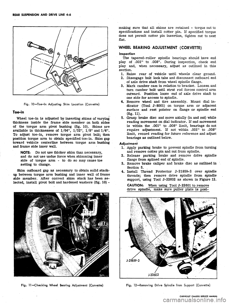
Fig.
10—Toe-in Adjusting Shim Location (Corvette)
Toe-in
Wheel toe-in is adjusted by inserting shims of varying
thickness inside the frame side member on both sides
of the torque arm pivot bushing (fig. 10). Shims are
available in thicknesses of
1/64",
1/32",
1/8" and 1/4".
To adjust toe-in, remove torque arm pivot bolt; then
position torque arm to obtain specified toe-in. Shim gap
toward vehicle centerline between torque arm bushing
and frame side inner wall.
NOTE: Do not use thicker shim than necessary,
and do not use undue force when shimming inner
side of torque arm - to do so may cause toe
setting to change.
Shim outboard gap as necessary to obtain solid stack-
up between torque arm bushing and inner wall of frame
side member. After correct shim stack has been se-
lected, install pivot bolt and hardened washers (fig. 10) -
making sure that all shims are retained - torque nut to
specifications and install cotter pin. If specified torque
does not permit cotter pin insertion, tighten nut to next
flat.
WHEEL BEARING ADJUSTMENT (CORVETTE)
inspection
The tapered-roller spindle bearings should have end
play of .001" to
.008".
During inspection, check end
play and, when necessary, adjust as outlined in this
section.
1.
Raise rear of vehicle until wheels clear ground.
2.
Disengage bolt lock tabs and disconnect outboard end
of axle drive shaft from wheel spindle flange.
3.
Mark camber cam in relation to bracket. Loosen and
turn camber bolt until strut rod forces control arm
outward. Position loose end of axle drive shaft to
one side for access to spindle.
4.
Remove wheel and tire assembly. Mount dial in-
dicator (Tool J-8001) on torque arm or adjacent
surface and rest pointer on flange or spindle end
(fig. H).
5.
Grasp brake disc and move axially (in and out) while
reading movement on dial indicator. If end movement
is within the .001" to .008" limit, bearings do not
require adjustment. If not within .001" to .008"
limit, record reading for future reference and adjust
bearings as outlined below.
Adjustment
1.
Apply parking brake to prevent spindle from turning
and remove cotter pin and nut from spindle.
2.
Release parking brake and remove drive spindle
flange from splined end of spindle.
3.
Remove brake caliper and brake disc as outlined in
Section 5.
4.
Install Thread Protector J-21859-2 over spindle
threads; then remove drive spindle from spindle
support, using Tool J-22602 as shown in Figure 12.
CAUTION: When using Tool J-22601 to remove
drive spindle, make sure puller plate is posi-
Fig.
11—Checking Wheel Bearing Adjustment (Corvette)
Fig. 12—Removing Drive Spindle from Support (Corvette)
CHEVROLET CHASSIS SERVICE MANUAL
Page 199 of 659
REAR SUSPENSION AND DRIVE LINE 4-9
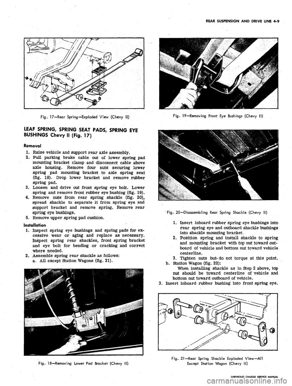
Fig.
17—Rear Spring—Exploded View (Chevy II)
LEAF SPRING, SPRING SEAT PADS, SPRING EYE
BUSHINGS Chevy II (Fig. 17)
Removal
1.
Raise vehicle and support rear axle assembly.
2.
Pull parking brake cable out of lower spring pad
mounting bracket clamp and disconnect cable above
axle housing. Remove four nuts securing lower
spring pad mounting bracket to axle spring seat
(fig. 18). Drop lower bracket and remove rubber
spring pad.
3.
Loosen and drive out front spring eye bolt. Lower
spring and remove front rubber eye bushing (fig. 19).
4.
Remove nuts from rear spring shackle (fig. 20),
spread shackle to separate it from spring eye and
support bracket and remove spring. Remove rear
spring eye bushings.
5.
Remove upper spring pad cushion.
Installation
1.
Inspect spring eye bushings and spring pads for ex-
cessive wear or aging and replace as necessary.
Inspect spring rear shackles, front spring bracket
and eye bolt for bending or cracking and correct
where needed.
2.
Assemble spring rear shackle as follows:
a. All except Station Wagons (fig. 21).
Fig.
19—Removing Front Eye Bushings (Chevy II)
3.
' Fig. 20—Disassembling Rear Spring Shackle (Chevy II)
1.
Insert inboard rubber spring eye bushings into
i'ear spring eye and outboard shackle bushings
into shackle mounting bracket.
2.
Position spring and install shackle to spring
and mounting bracket with top nut toward out-
board of vehicle and bottom nut toward vehicle
centerline.
3.
Tighten nuts but-do not torque at this point,
b.
Station Wagon (fig. 22):
When installing shackle as in Step 2 above, top
nut should be toward centerline of vehicle and
bottom nut toward outboard of vehicle.
Insert inboard rubber bushing into front spring eye.
Fig.
18—Removing Lower Pad Bracket (Chevy II)
Fig.
21—Rear Spring Shackle Exploded View-All
Except Station Wagon (Chevy II)
CHEVROLET CHASSIS SERVICE MANUAL
Page 201 of 659
REAR SUSPENSION AND DRIVE LINE 4-11
lower cushion
correct.
will be aligned if installation is
Fig.
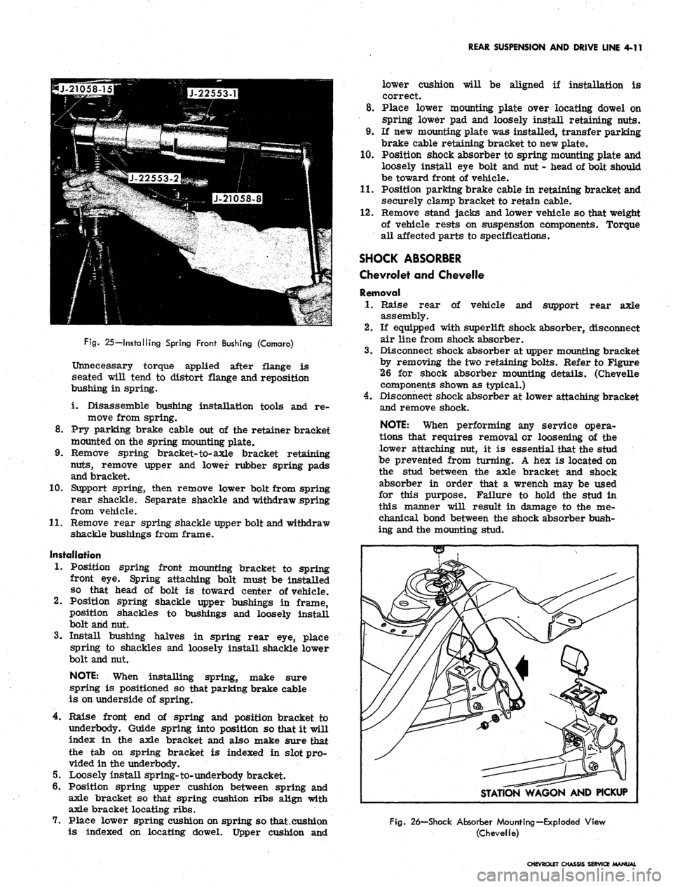
25—Installing Spring Front Bushing (Camaro)
Unnecessary torque applied after flange is
seated will tend to distort flange and reposition
bushing in spring.
i. Disassemble bushing installation tools and re-
move from spring.
8. Pry parking brake cable out of the retainer bracket
mounted on the spring mounting plate.
9. Remove spring bracket-to-axle bracket retaining
nuts,
remove upper and lower rubber spring pads
and bracket.
10.
Support spring, then remove lower bolt from spring
rear shackle. Separate shackle and withdraw spring
from vehicle.
11.
Remove rear spring shackle upper bolt and withdraw
shackle bushings from frame.
Installation
1.
Position spring front mounting bracket to spring
front eye. Spring attaching bolt must be installed
so that head of bolt is toward center of vehicle.
2.
Position spring shackle upper bushings in frame,
position shackles to bushings and loosely install
bolt and nut.
3.
Install bushing halves in spring rear eye, place
spring to shackles and loosely install shackle lower
bolt and nut.
NOTE: When installing spring, make sure
spring is positioned so that parking brake cable
is on underside of spring.
4.
Raise front end of spring and position bracket to
underbody. Guide spring into position so that it will
index in the axle bracket and also make sure that
the tab on spring bracket is indexed in slot pro-
vided in the underbody.
5.
Loosely install spring-to-underbody bracket.
6. Position spring upper cushion between spring and
axle bracket so that spring cushion ribs align with
axle bracket locating ribs.
7.
Place lower spring cushion on spring so that .cushion
is indexed on locating dowel. Upper cushion and
8. Place lower mounting plate over locating dowel on
spring lower pad and loosely install retaining nuts.
9. If new mounting plate was installed, transfer parking
brake cable retaining bracket to new plate.
10.
Position shock absorber to spring mounting plate and
loosely install eye bolt and nut - head of bolt should
be toward front of vehicle.
11.
Position parking brake cable in retaining bracket and
securely clamp bracket to retain cable.
12.
Remove stand jacks and lower vehicle so that weight
of vehicle rests on suspension components. Torque
all affected parts to specifications.
SHOCK ABSORBER
Chevrolet and Chevelle
Removal
1.
Raise rear of vehicle and support rear axle
assembly.
If equipped with superlift shock absorber, disconnect
air line from shock absorber.
Disconnect shock absorber at upper mounting bracket
by removing the two retaining bolts. Refer to Figure
26 for shock absorber mounting details. (Chevelle
components shown as typical.)
Disconnect shock absorber at lower attaching bracket
and remove shock.
NOTE: When performing any service opera-
tions that requires removal or loosening of the
lower attaching nut, it is essential that the stud
be prevented from turning. A hex is located on
the stud between the axle bracket and shock
absorber in order that a wrench may be used
for this purpose. Failure to hold the stud in
this manner will result in damage to the mer
chanical bond between the shock absorber bush-
ing and the mounting stud.
2.
3.
STATION WAGON AND PICKUP
Fig.
26—Shock Absorber Mounting—Exploded View
(Chevelle)
CHEVROLET CHASSIS SERVICE MANUAL
Page 202 of 659
REAR SUSPENSION AND DRIVE LINE 4-12
Fig.
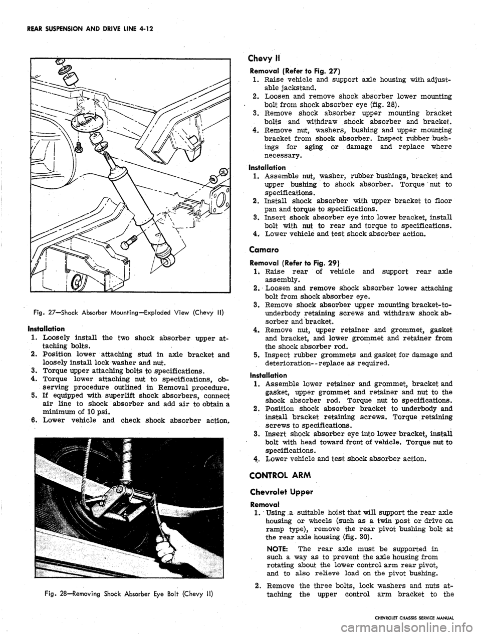
27—Shock Absorber Mounting—Exploded View (Chevy II)
Installation
1.
Loosely install the two shock absorber upper at-
taching bolts.
2.
Position lower attaching stud in axle bracket and
loosely install lock washer and nut.
3.
Torque upper attaching bolts to specifications.
4.
Torque lower attaching nut to specifications, ob-
serving procedure outlined in Removal procedure.
5.
If equipped with superlift shock absorbers, connect
air line to shock absorber and add air to obtain a
minimum of 10 psi.
6. Lower vehicle and check shock absorber action.
Fig.
28—Removing Shock Absorber Eye Bolt (Chevy II)
Chevy H
Removal (Refer to Fig. 27)
1.
Raise vehicle and support axle housing with adjust-
able jackstand.
2.
Loosen and remove shock absorber lower mounting
bolt from shock absorber eye (fig. 28).
3.
Remove shock absorber upper mounting bracket
bolts and withdraw shock absorber and bracket.
4.
Remove nut, washers, bushing and upper mounting
bracket from shock absorber. Inspect rubber bush-
ings for aging or damage and replace where
necessary.
Installation
1.
Assemble nut, washer, rubber bushings, bracket and
upper bushing to shock absorber. Torque nut to
specifications.
2.
Install shock absorber with upper bracket to floor
pan and torque to specifications.
3.
Insert shock absorber eye into lower bracket, install
bolt with nut to rear and torque to specifications.
4.
Lower vehicle and test shock absorber action.
Comoro
Removal (Refer to Fig. 29)
1.
Raise rear of vehicle and support rear axle
assembly.
2.
Loosen and remove shock absorber lower attaching
bolt from shock absorber eye.
3.
Remove shock absorber upper mounting bracket-to-
iiinderbody retaining screws and withdraw shock ab-
sorber and bracket.
4.
Remove nut, upper retainer and grommet, gasket
and bracket, and lower grommet and retainer from
the shock absorber rod.
5.
Inspect rubber grommets and gasket for damage and
deterioration--replace as required.
Installation
1.
Assemble lower retainer and grommet, bracket and
gasket, upper grommet and retainer and nut to the
shock absorber rod. Torque nut to specifications.
2.
Position shock absorber bracket to underbody and
install bracket retaining screws. Torque retaining
screws to specifications.
3.
Insert shock absorber eye into lower bracket, install
bolt with head toward front of vehicle. Torque nut to
specifications.
4.
Lower vehicle and test shock absorber action.
CONTROL ARM
Chevrolet Upper
Removal
1.
*
Using,a suitable hoist that will support the rear axle
housing or wheels (such as a twin post or drive on
ramp type), remove the rear pivot bushing bolt at
the rear axle housing (fig. 30).
NOTE: The rear axle must be supported in
such a way as to prevent the axle housing from
rotating about the lower control arm rear pivot,
and to also relieve load on the pivot bushing.
2.
Remove the three bolts, lock washers and nuts at-
taching the upper control arm bracket to the
CHEVROLET CHASSIS SERVICE MANUAL