ECU CHEVROLET CAMARO 1967 1.G Chassis Owner's Manual
[x] Cancel search | Manufacturer: CHEVROLET, Model Year: 1967, Model line: CAMARO, Model: CHEVROLET CAMARO 1967 1.GPages: 659, PDF Size: 114.24 MB
Page 212 of 659
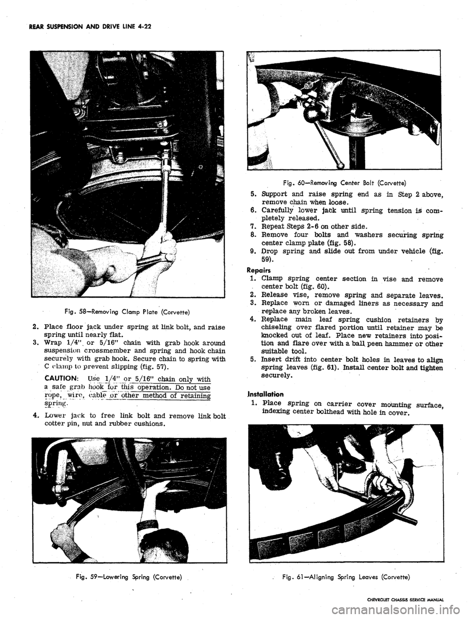
REAR SUSPENSION AND DRIVE LINE 4-22
Fig.
58—Removing Clamp Plate (Corvette)
2.
Place floor jack under spring at link bolt, and raise
spring until nearly flat.
3.
Wrap 1/4", or 5/16" chain with grab hook around
suspension crossmember and spring and hook chain
securely with grab hook. Secure chain to spring with
C ela rnp to prevent slipping (fig. 57).
CAUTION: Use 1/4" or 5/16" chain only with
a sate grab hoo^for this operation. Do not use
rope,
wiro, cable .or other method of retaining
spring.
4.
Lower jack to free link bolt and remove link bolt
cotter pin, nut and rubber cushions.
Fig.
60—Removing Center Boit (Corvette)
5.
Support and raise spring end as in Step 2 above,
remove chain when loose.
6. Carefully lower jack until spring tension is com-
pletely released.
7.
Repeat Steps 2-6 on other side.
8. Remove four bolts and washers securing spring
center clamp plate (fig. 58).
9. Drop spring and slide out from under vehicle (fig.
59).
Repairs
•1.
Clamp spring center section in vise and remove
. center bolt (fig. 60).
2.
Release vise, remove spring and separate leaves.
3.
Replace worn or damaged liners as necessary and
replace any broken leaves.
4.
Replace main leaf spring cushion retainers by
chiseling over flared portion until retainer may be
knocked out of
leaf.
Place new retainers into posi-
tion and flare over with a ball peen hammer or other
suitable tool.
5.
Insert drift into center bolt holes in leaves to align
spring leaves (fig. 61). Install center bolt and tighten
securely.
installation
1.
Place spring on carrier cover mounting surface,
indexing center bolthead with hole in cover.
Fig.
59—Lowering Spring (Corvette)
Fig.
61—-Aligning Spring Leaves (Corvette)
CHEVROLET CHASSIS SERVICE MANUAL
Page 213 of 659
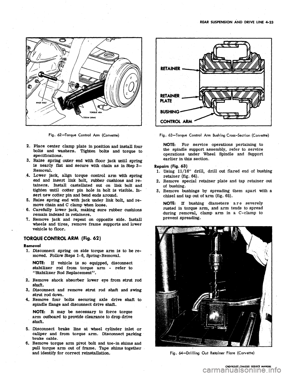
REAR SUSPENSION AND DRIVE LINE 4-23
Fig.
62—Torque Control Arm (Corvette)
2.
Place center clamp plate in position and install four
bolts and washers. Tighten bolts and torque to
specifications.
3.
Raise spring outer end with floor jack until spring
is nearly flat and secure with chain as in Step 3-
Removal.
.4.
Lower jack, align torque control arm with spring
end and insert link bolt, rubber cushions and re-
tainers. Install castellated nut on link bolt and
tighten until cotter pin hole in bolt is visible. In-
sert new cotter pin and bend ends around.
5. Raise spring end with jack under link bolt, and re-
move chain and C clamp when loose.
6. Carefully lower jack, making sure rubber cushions
remain indexed in retainers.
7. Remove jack and repeat on opposite side. Install
wheels and tires, remove frame supports and lower
vehicle to floor.
TORQUE CONTROL ARM (Fig. 62)
Removal
1.
Disconnect spring on side torque arm is to be re-
moved. Follow Steps 1-6, Spring-Removal.
NOTE:
If vehicle is so equipped, disconnect
stabilizer rod from torque arm - refer to
"Stabilizer Rod Replacement".
2.
Remove shock absorber lower eye from strut rod
shaft.
3.
Disconnect and remove strut rod shaft and swing
strut rod down.
4.
Remove four bolts securing axle drive shaft to
spindle flange and disconnect drive shaft.
NOTE:
It may be necessary to force torque
arm outboard to provide clearance to drop drive
shaft.
5. Disconnect brake line at wheel cylinder inlet or
caliper and from torque arm. Disconnect parking
brake cable.
6. Remove torque arm pivot bolt and toe-in shims and
pull torque arm out of frame. Tape shims together
and identify for correct reinstallation.
RETAINER
RETAINER
PLATE
BUSHING
CONTROL ARM
Fig.
63—Torque Control Arm Bushing Cross-Sect ion (Corvette)
NOTE:
For service operations pertaining to
the spindle support assembly, refer to service
operations under Wheel Spindle and Support
earlier in this section.
Repairs (Fig. 63)
1.
Using 11/16" drill, drill out flared end of bushing
retainer (fig. 64).
2.
Remove special retainer plate and tap retainer out
of bushing.
3.
Remove bushings by spreading them apart with a
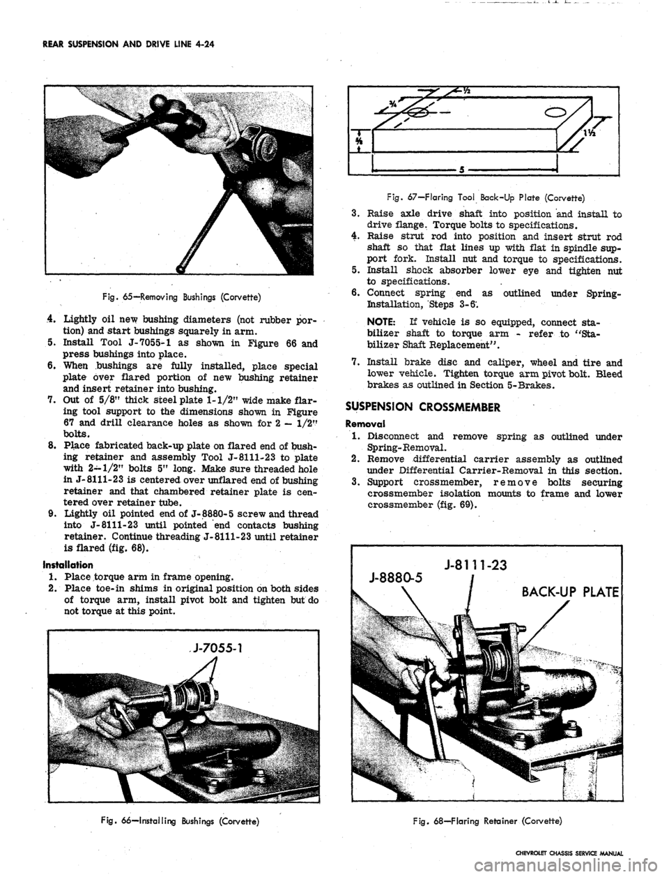
chisel and tap out of arm (fig. 65).
NOTE:
If bushing diameters are severely
rusted in torque arm, and arm tends to spread
during removal, clamp arm in a C-clamp to
prevent spreading.
Fig.
64—Drilling Out Retainer Flare (Corvette)
CHEVROLET CHASSIS SERVICE MANUAL
Page 214 of 659
REAR SUSPENSION AND DRIVE LINE 4-24
4
i*
5
Fig.
65—Removing Bushings (Corvette)
4.
Lightly oil new bushing diameters (not rubber por-
tion) and start bushings squarely in arm.
5. Install Tool J-7055-1 as shown in Figure 66 and
press bushings into place.
6. When bushings are fully installed, place special
plate over flared portion of new bushing retainer
and insert retainer into bushing.
7. Out of 5/8" thick steel plate 1-1/2" wide make flar-
ing tool support to the dimensions shown in Figure
67 and drill clearance holes as shown for 2
—
1/2"
bolts.
8. Place fabricated back-up plate on flared end of bush-
ing retainer and assembly Tool J-8111-23 to plate
with 2-1/2" bolts 5" long. Make sure threaded hole
in J-8111-23 is centered over unflared end of bushing
retainer and that chambered retainer plate is cen-
tered over retainer tube.
9. Lightly oil pointed end of J-8880-5 screw and thread
into J-
8111-23
until pointed "end contacts bushing
retainer. Continue threading J-8111-23 until retainer
is flared (fig. 68).
Installation
1.
Place torque arm in frame opening.
2.
Place toe-in shims in original position on both sides
of torque arm, install pivot bolt and tighten but do
not torque at this point.
Fig.
67—Flaring Tool Back-Up Plate (Corvette)
3.
Raise axle drive shaft into position and install to
drive flange. Torque bolts to specifications.
4.
Raise strut rod into position and insert strut rod
shaft so that flat lines up with flat in spindle sup-
port fork. Install nut and torque to specifications.
5. Install shock absorber lower eye and tighten nut
to specifications.
6. Connect spring end as outlined under Spring-
Bistallation, Steps 3-6'.
NOTE:
If vehicle is so equipped, connect sta-
bilizer shaft to torque arm - refer to "Sta-
bilizer Shaft Replacement".
7. Install brake disc and caliper, wheel and tire and
lower vehicle. Tighten torque arm pivot bolt. Bleed
brakes as outlined in Section 5-Brakes.
SUSPENSION CROSSMEMBER
Removal
1.
Disconnect and remove spring as outlined under
Spring-Removal.
2.
Remove differential carrier assembly as outlined
under Differential Carrier-Removal in this section.
3.
Support crossmember, remove bolts securing
crossmember isolation mounts to frame and lower
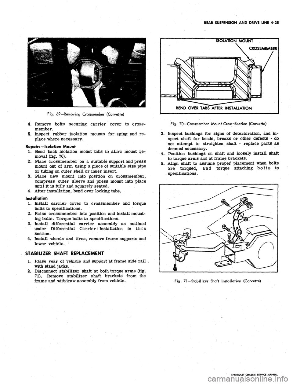
crossmember (fig. 69).
Fig.
66—Installing Bushings (Corvette)
Fig.
68—Flaring Retainer (Corvette)
CHEVROLET CHASSIS SERVICE MANUAL
Page 215 of 659
REAR SUSPENSION AND DRIVE LINE 4-25
Fig.
69—Removing Crossmember (Corvette)
4.
Remove bolts securing carrier cover to cross-
member.
5.
Inspect rubber isolation mounts for aging and re-
place where necessary.
Repairs—Isolation Mount
1.
Bend back isolation mount tabs to allow mount re-
moval (fig. 70).
2.
Place crossmember on a suitable support and press
mount out of arm using a piece of suitable size pipe
or tubing on outer shell or inner insert.
3.
Place new mount into position on crossmember,
compress outer sleeve and press mount into place
until it is fully and squarely seated.
4.
After installation, bend over locking tabs.
Installation
1.
Install carrier cover to crossmember and torque
bolts to specifications.
2.
Raise crossmember into position and install mount-
ing bolts. Torque bolts to specifications.
3.
Install differential carrier assembly as outlined
under Differential Carrier
-
Installation in this
section.
4.
Install wheels and tires, remove frame supports and
lower vehicle.
STABILIZER SHAFT REPLACEMENT
1.
Raise rear of vehicle and support at frame side rail
with stand jacks.
2.
Disconnect stabilizer shaft at both torque arms (fig.
71).
Remove stabilizer shaft brackets from the
frame and withdraw assembly from vehicle.
ISOLATION MOUNT
CROSSMEMBER
BEND OVER TABS AFTER INSTALLATION
Fig.
70—Crossmember Mount Cross-Section (Corvette)
3.
Inspect bushings for signs of deterioration, and in-
spect shaft for bends, breaks or other defects - do
not attempt to straighten shaft - replace parts as
deemed necessary.
4.
Position bushings on shaft and loosely install shaft
to torque arms and at frame brackets.
5.
Align shaft to assume proper placement when bolts
are torqued, and torque attaching bolts to
specifications.
Fig.
71—Stabilizer Shaft Installation (Corvette)
CHEVROLET CHASSIS SERVICE MANUAL
Page 217 of 659
REAR SUSPENSION AND DRIVE LINE 4-27
SHIM AND
SERVICE
12
14
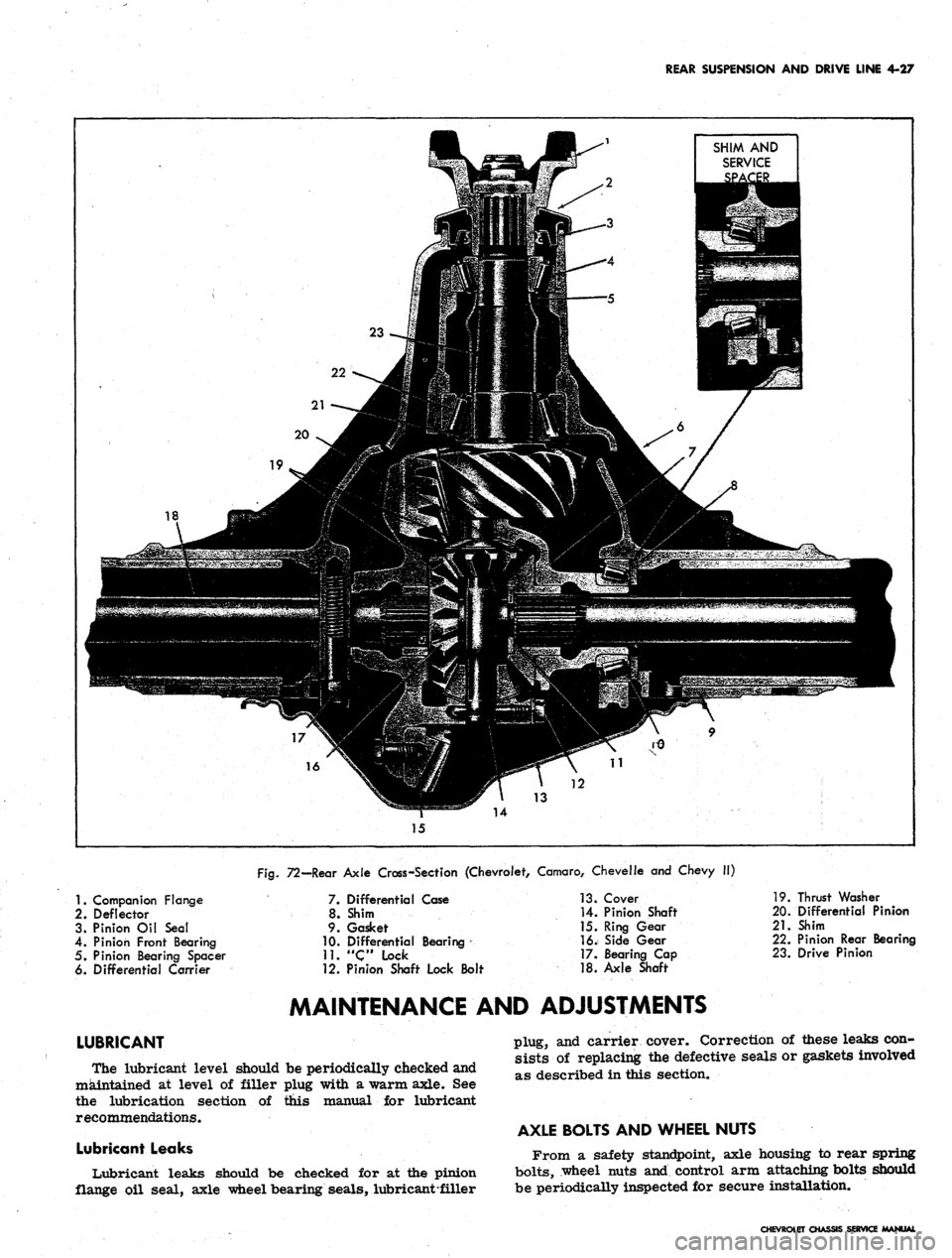
Fig.
72—Rear Axle Cross-Section (Chevrolet, Camaro, Chevelle and Chevy II)
1.
Companion Flange
2.
Deflector
3. Pinion Oil Seal
4.
Pinion Front Bearing
5. Pinion Bearing Spacer
6. Differential Carrier
LUBRICANT
7. Differential Case
8. Shim
9. Gasket
10.
Differential Bearing
11.
"Clock
12. Pinion Shaft Lock Bolt
13.
Cover
14.
Pinion Shaft
15.
Ring Gear
16.
Side Gear
17.
Bearing Cap
18.
Axle Shaft
19.
Thrust Washer
20.
Differential Pinion
21.
Shim
22.
Pinion Rear Bearing
23.
Drive Pinion
MAINTENANCE AND ADJUSTMENTS
The lubricant level should be periodically checked and
maintained at level of filler plug with a warm axle. See
the lubrication section of this manual for lubricant
recommendations.
Lubricant Leaks
Lubricant leaks should be checked for at the pinion
flange oil seal, axle wheel bearing seals, lubricant-filler
plug, and carrier cover. Correction of these leaks con-
sists of replacing the defective seals or gaskets involved
as described in this section.
AXLE BOLTS AND WHEEL NUTS
From a safety standpoint, axle housing to rear spring
bolts,
wheel nuts and control arm attaching bolts should
be periodically inspected for secure installation.
CHEVROLET CHASSIS SERVICE MANUAL
Page 220 of 659
REAR SUSPENSION AND DRIVE LINE 4-30
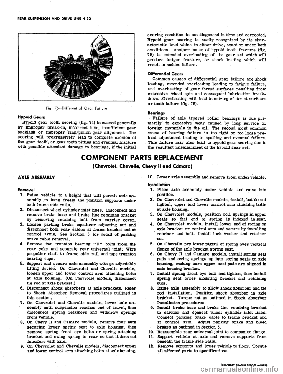
Fig.
76—Differential Gear Failure
Hypoid Gears
Hypoid gear tooth scoring (fig. 74) is caused generally
by improper break-in, incorrect lube, insufficient gear
backlash or improper 'ring/pinion gear alignment. The
scoring will progressively lead to complete erosion of
the gear tooth, or gear tooth pitting and eventual fracture
with possible attendant damage to bearings, if the initial
scoring condition is not diagnosed in time and corrected.
Hypoid gear scoring is easily recognized by its char-
acteristic loud whine in either drive, coast or under both
conditions. Another cause of hypoid tooth fracture (fig.
75) is extended overloading of the gear set which will
produce fatigue fracture, or shock loading which will
result in sudden failure.
Differential Gears
Common causes of differential gear failure are shock
loading, extended overloading leading to fatigue failure,
and overheating of gear thrust surfaces resulting from
excessive wheel spin and consequent lubrication break-
down. Overheating will lead to seizing of thrust surfaces
or tooth failure (fig. 76).
Bearings
• Failure of axle tapered roller bearings is due pri-
marily to excessive wear caused by long service or
foreign materials in the oil. The second most common
cause of bearing failure is too tight or too loose pre-
load adjustment leading to spalling and eventual failure.
This failure may also lead to hypoid gear scoring due to
the resultant misalignment of the hypoid gear set.
COMPONENT PARTS REPLACEMENT
(Chevrolet, Cheveile, Chevy II and Camaro)
AXLE ASSEMBLY
Removal
1.
Raise vehicle to a height that will permit axle as-
sembly to hang freely and position supports under
both frame side rails.
2.
Disconnect wheel cylinder inlet lines. Disconnect and
remove brake hose and brake line retaining bracket
by removing retaining bolt from carrier cover.
3.
Loosen parking brake equalizer adjusting nut and
disconnect both rear cables at frame bracket and at
control arms. See Section 5 for detail of parking
brake cable removal.
4.
Remove two trunnion bearing "U" bolts from the
rear yoke and separate rear universal joint. Wire
propeller shaft to frame side rail and tape trunnion
bearing cups.
5. Support arid secure axle assembly with an adjustable
lifting device. On Chevrolet and Cheveile models,
loosen upper and lower control arm attaching bolts
at axle housing. (On Chevrolet models, disconnect
tie rod at axle bracket.)
6. Disconnect shock absorbers at axle brackets. Refer
to Shock Absorber Removal procedures outlined in
this section.
7. On Chevrolet and Cheveile models, lower axle as-
sembly until suspension reaches end of travel, then
disconnect spring retainers and withdraw springs
from vehicle.
8. On Chevy II and Camaro models, remove four nuts
securing lower spring seat to axle housing, then
remove spring front eye bolts or spring attaching
bracket and swing spring to rear so that it does not
interfere with axle.
9. On Chevrolet and Cheveile models, disconnect upper
and lower control arm attaching bolts at axle housing*
10.
Lower axle assembly and remove from under vehicle.
Installation
1.
Place axle assembly under vehicle and raise into
position.
2.
On Chevrolet and Cheveile models, install, but do not
tighten, upper and lower control arm attaching bolts
at axle housing.
3.
On Chevrolet models, position coil springs in upper
seats so that end of spring is indexed in seat.
4.
On Chevrolet models, install lower end of spring on
axle bracket or control arm and secure by installing
retainer and bolt. Install lock washer and retainer
nut.
5. On Cheveile pry lower pigtail of spring over vertical
flange of the axle bracket spring seat.
6. On Chevy II and Camaro models, install spring seat
pads and swing springs up into spring seats on axle
housing, making sure upper seat pads are aligned in
axle housing bracket.
7. Install spring front eye bolt and tighten, then install
spring seat lower mounting bracket and retaining
nuts.
8. Raise axle assembly to allow shock absorber and tie
rod installation. Position shock absorber in axle
bracket. Torque nut as outlined in Shock Absorber
Installation procedures.
9. Install brake hose and brake line retaining bracket
to carrier and connect wheel cylinder inlet lines.
Connect parking brake cable to frame bracket and
at control arm. Adjust parking brake and bleed
brakes as outlined in Section 5.
10.
Reassemble rear universal joint to companion flange.
11.
Support vehicle at axle and remove supports from
beneath the frame side rails.
12.
Remove supports and lower vehicle to floor. Torque
all affected parts to specifications.
CHEVROLET CHASSIS SERVICE MANUAL
Page 221 of 659
REAR SUSPENSION AND DRIVE LINE 4-31
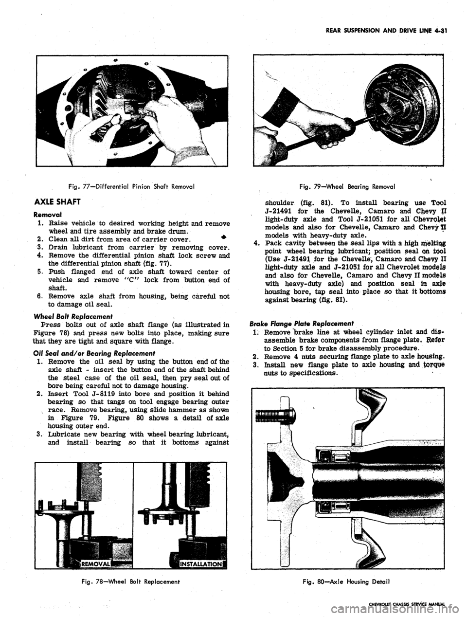
Fig.
77—Differential Pinion Shaft Removal
AXLE SHAFT
Removal
1.
Raise vehicle to desired working height and remove
wheel and tire assembly and brake drum.
2.
Clean all dirt from area of carrier cover. *
3.
Drain lubricant from carrier by removing cover.
4.
Remove the differential pinion shaft lock screw and
the differential pinion shaft (fig. 77).
5. Push flanged end of axle shaft toward center of
vehicle and remove "C" lock from button end of
shaft.
6. Remove axle shaft from housing, being careful not
to damage oil seal.
Wheel Bolt Replacement .
Press bolts out of axle shaft flange (as illustrated in
Figure 78) and press new bolts into place, making sure
that they are tight and square with flange.
Off Seal and/or Bearing Replacement
•1.
Remove the oil seal by using the button end of the
axle shaft - insert the button end of the shaft behind
the steel case of the oil seal, then pry seal out of
bore being careful not to damage housing.
2.
Insert Tool J-8119 into bore and position it behind
bearing so that tangs on tool engage bearing outer
x race. Remove bearing, using slide hammer as shown
in Figure 79. Figure 80 shows a detail of axle
housing outer end.
3.
Lubricate new bearing with wheel bearing lubricant,
and install bearing so that it bottoms against
Fig.
79—Wheel Bearing Removal
shoulder (fig. 81). To install bearing use Tool
J-21491 for the Chevelle, Camaro and Chevy JI
light-duty axle and Tool J-21051 for all Chevrolet
models and also for Chevelle, Camaro and Chevy tl
models with heavy-duty axle.
Pack cavity between the seal lips with a high melting
point wheel bearing lubricant; position seal on tool
(Use J-21491 for the Chevelle, Camaro and Chevy II
light-duty axle and J-21051 for all Chevrolet models
and also for Chevelle, Camaro and Chevy II models
with heavy-duty axle) and position seal in axle
housing bore, tap seal into place so that it bottoms
against bearing (fig. 81).
Brake Flange Plate Replacement
1.
Remove "brake line at wheel cylinder inlet and dis-
assemble brake components from flange plate. Refer
to Section 5 for brake disassembly procedure.
2.
Remove 4 nuts securing flange plate to axle housing.
3.
Install new flange plate to axle housing and torque
nuts to specifications.
Fig.
78—Wheel Bolt Replacement
Fig.
80-Axle Housing Detail
CHEVROLET CHASSIS SERVICE MANUAL
Page 224 of 659
REAR SUSPENSION AND DRIVE LINE 4-34
COMPONENT PARTS REPLACEMENT (CORVETTE)
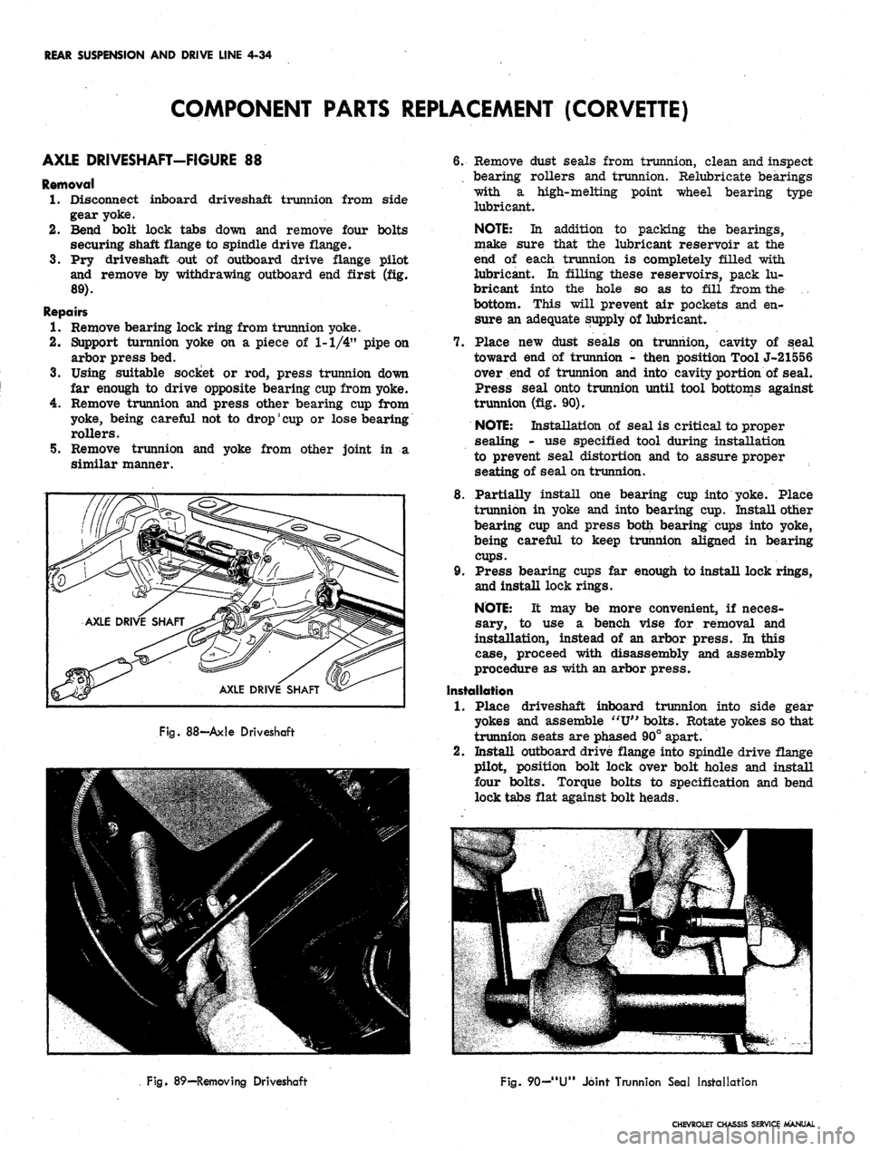
AXLE DRIVESHAFT-FIGURE 88
Removal
1.
Disconnect inboard driveshaft trunnion from side
gear yoke.
2.
Bend bolt lock tabs down and remove four bolts
securing shaft flange to spindle drive flange.
3.
Pry driveshaft out of outboard drive flange pilot
and remove by withdrawing outboard end first (fig.
89).
Repairs
1.
Remove bearing lock ring from trunnion yoke.
2.
Support turnnion yoke on a piece of 1-1/4" pipe on
arbor press bed.
3.
Using suitable socket or rod, press trunnion down
far enough to drive opposite bearing cup from yoke.
4.
Remove trunnion and press other bearing cup from
yoke, being careful not to
drop'
cup
or lose bearing
rollers.
5. Remove trunnion and yoke from other joint in a
similar manner.
3
AXLE
II 1
i
c
DRI\
c
y
'E SHAFT ^
AXLE
v
DRIVE^
SHAFT
•
Fig.
88—Axle Driveshaft
6. Remove dust seals from trunnion, clean and inspect
bearing rollers and trunnion. Relubricate bearings
with a high-melting point wheel bearing type
lubricant.
NOTE:
In addition to packing the bearings,
make sure that the lubricant reservoir at the
end of each trunnion is completely filled with
lubricant. In filling these reservoirs, pack lu-
bricant into the hole so as to fill from the .
bottom. This will prevent air pockets and en-
sure an adequate supply of lubricant.
7. Place new dust seals on trunnion, cavity of seal
toward end of trunnion - then position Tool J-21556
over end of trunnion and into cavity portion of seal.
Press seal onto trunnion until tool bottoms against
trunnion (fig. 90).
NOTE:
Installation of seal is critical to proper
sealing - use specified tool during installation
to prevent seal distortion and to assure proper
seating of seal on trunnion.
8. Partially install one bearing cup into yoke. Place
trunnion in yoke and into bearing cup. Install other
bearing cup and press both bearing cups into yoke,
being careful to keep trunnion aligned in bearing
cups.
9. Press bearing cups far enough to install lock rings,
and install lock rings.
NOTE:
It may be more convenient, if neces-
sary, to use a bench vise for removal and
installation, instead of an arbor press. In this
case, proceed with disassembly and assembly
procedure as with an arbor press.
Installation
1.
Place driveshaft inboard trunnion into side gear
yokes and assemble
"XJ"
bolts. Rotate yokes so that
trunnion seats are phased 90° apart.
2.
Install outboard drive flange into spindle drive flange
pilot, position bolt lock over bolt holes and install
four bolts. Torque bolts to specification and bend
lock tabs flat against bolt heads.
Fig. 89—Removing Driveshaft
Fig.
90—
"U"
Joint Trunnion Seal Installation
CHEVROLET CHASSIS SERVICE MANUAL
Page 226 of 659
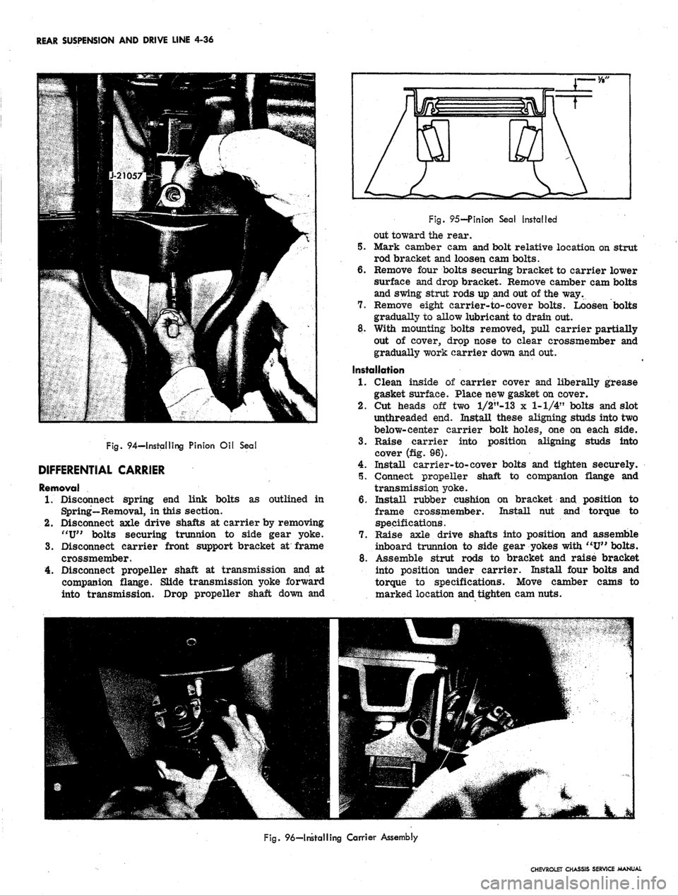
REAR SUSPENSION AND DRIVE LINE 4-36
Fig.
94—Installing Pinion Oil Seal
DIFFERENTIAL CARRIER
Removal
1.
Disconnect spring end link bolts as outlined in
Spring—Removal, in this section.
2.
Disconnect axle drive shafts at carrier by removing
"U"
bolts securing trunnion to side gear yoke.
3.
Disconnect carrier front support bracket at frame
crossmember.
4.
Disconnect propeller shaft at transmission and at
companion flange. Slide transmission yoke forward
into transmission. Drop propeller shaft down and
Fig.
95-Pinion Sea! Installed
out toward the rear.
5. Mark camber cam and bolt relative location on strut
rod bracket and loosen cam bolts.
6. Remove four bolts securing bracket to carrier lower
surface and drop bracket. Remove camber cam bolts
and swing strut rods up and out of the way.
7. Remove eight carrier-to-cover bolts. Loosen bolts
gradually to allow lubricant to drain out.
8. With mounting bolts removed, pull carrier partially
out of cover, drop nose to clear crossmember and
gradually work carrier down and out.
Installation
1.
Clean inside of carrier cover and liberally grease
gasket surface. Place new gasket on cover.
2.
Cut heads off two l/2"-13 x 1-1/4" bolts and slot
unthreaded end. Install these aligning studs into two
below-center carrier bolt holes, one on each side.
3.
Raise carrier into position aligning studs into
cover (fig. 96).
4.
Install carrier-to-cover bolts and tighten securely.
5. Connect propeller shaft to companion flange and
transmission yoke.
6. Install rubber cushion on bracket and position to
frame crossmember. Install hut and torque to
specifications.
7. Raise axle drive shafts into position and assemble
inboard trunnion to side gear yokes with "U" bolts.
8. Assemble strut rods to bracket and raise bracket
into position under carrier. Install four bolts and
torque to specifications. Move camber cams to
marked location and tighten cam nuts.
Fig.
96—Installing Carrier Assembly
CHEVROLET CHASSIS SERVICE MANUAL
Page 238 of 659
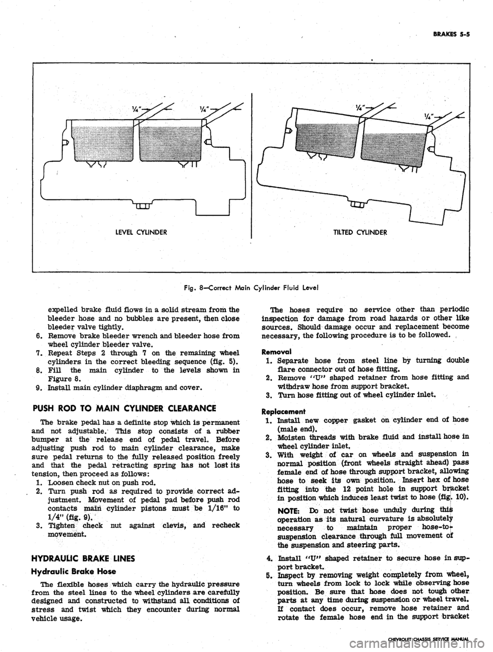
BRAKES 5-5
LEVEL CYLINDER
TILTED CYLINDER
Fig.
8—Correct Main Cylinder Fluid Level
expelled brake fluid flows in a solid stream from the
bleeder hose and no bubbles are present, then close
bleeder valve tightly.
6. Remove brake bleeder wrench and bleeder hose from
wheel cylinder bleeder valve.
7. Repeat Steps 2 through 7 on the remaining wheel
cylinders in the correct bleeding sequence (fig. 5).
8. Fill the main cylinder to the levels shown in
Figure 8.
9. Install main cylinder diaphragm and cover.
PUSH ROD TO MAIN CYLINDER CLEARANCE
The brake pedal has a definite stop which is permanent
and not adjustable. This stop consists of a rubber
bumper at the release end of pedal travel. Before
adjusting push rod to main cylinder clearance, make
sure pedal returns to the fully released position freely
and that the pedal retracting spring has hot lost its
tension, then proceed as follows:
1.
Loosen check nut on push rod.
2.
Turn push rod as required to provide correct ad-
justment. Movement of pedal pad before push rod
contacts main cylinder pistons must be 1/16" to
1/4" (fig. 9).
3.
Tighten check nut against clevis, and recheck
movement.
HYDRAULIC BRAKE LINES
Hydraulic Brake Hose
The flexible hoses which carry the hydraulic pressure
from the steel lines to the wheel cylinders are carefully
designed and constructed to withstand all conditions of
stress and twist which they encounter during normal
vehicle usage.
The hoses require no service other than periodic
inspection for damage from road hazards or other like
sources. Should damage occur and replacement become
necessary, the following procedure is to be followed.
Removal
1.
Separate hose from steel line by turning double
flare connector out of hose fitting.
2.
Remove "U" shaped retainer from hose fitting and
withdraw hose from support bracket.
3.
Turn hose fitting out of wheel cylinder inlet.
Replacement
1.
Install new copper gasket on cylinder end of hose
(male end).
2.
Moisten threads with brake fluid and install hose in
wheel cylinder inlet.
3.
With weight of car on wheels and suspension in
normal position (front wheels straight ahead) pass
female end of hose through support bracket, allowing
hose to seek its own position. Insert hex of hose
fitting into the 12 point hole in support bracket
in position which induces least twist to hose (figk 10).
NOTE:
Do not twist hose unduly during ^
operation as its natural curvature is absolutely
necessary to maintain proper hose-tot
suspension clearance through full movement o£
the suspension and steering parts.
4.
Install "U" shaped retainer to secure hose in sup-
port bracket.
5. Inspect by removing weight completely from wheel,
turn wheels from lock to lock while observing hose
position. Be sure that hose does not tough other
parts at any time during suspension or wheel travel.
If contact does occur, remove hose retainer and
rotate the female hose end in the support bracket
CHEVROLET CHASSIS SERVICE MANUAL