CHEVROLET CAMARO 1967 1.G Chassis Workshop Manual
Manufacturer: CHEVROLET, Model Year: 1967, Model line: CAMARO, Model: CHEVROLET CAMARO 1967 1.GPages: 659, PDF Size: 114.24 MB
Page 461 of 659
STEERING 9-21
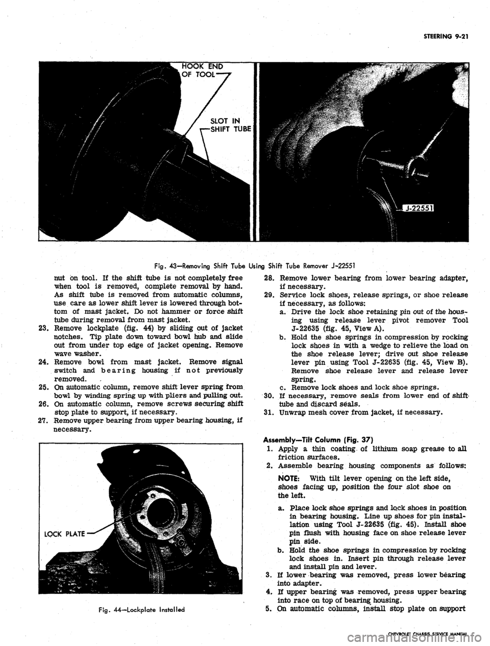
Fig.
43-Removing Shift Tube Using Shift Tube Remover J-22551
nut on tool. If the shift tube is not completely free
when tool is removed, complete removal by hand.
As shift tube is removed from automatic columns,
use care as lower shift lever is lowered through bot-
tom of mast jacket. Do not hammer or force shift
tube during removal from mast jacket.
23.
Remove lockplate (fig. 44) by sliding out of jacket
notches. Tip plate down toward bowl hub and slide
out from under top edge of jacket opening. Remove
wave washer.
24.
Remove bowl from mast jacket. Remove signal
switch and bearing housing if not previously
removed.
25.
On automatic column, remove shift lever spring from
bowl by winding spring up with pliers and pulling out.
26.
On automatic column, remove screws securing shift
stop plate to support, if necessary.
27.
Remove upper bearing from upper bearing housing, if
necessary.
Fig.
44—Lockplate Installed
28.
Remove lower bearing from lower bearing adapter,
if necessary.
29.
Service lock shoes, release springs, or shoe release
if necessary, as follows:
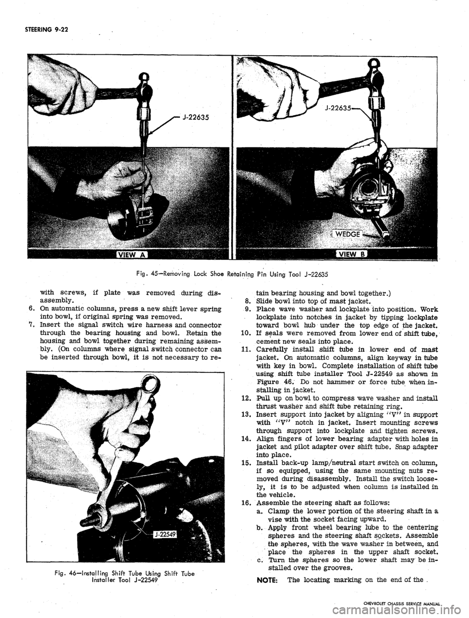
a. Drive the lock shoe retaining pin out of the hous-
ing using release lever pivot remover Tool
J-22635 (fig. 45, View A).
b.
Hold the shoe springs in compression by rocking
lock shoes in with a wedge to relieve the load on
the shoe release lever; drive out shoe release
lever pin using Tool J-22635 (fig. 45, View B).
Remove shoe release lever and release lever
spring.
c. Remove lock shoes and lock shoe springs.
30.
If necessary, remove seals from lower end of shift-
tube and discard seals.
31.
Unwrap mesh cover from jacket, if necessary.
Assembly-Tilt Column (Fig. 37)
1.
Apply a thin coating of lithium soap grease to all
friction surfaces.
2.
Assemble bearing housing components as follows:
NOTE:
With tilt lever opening on the left side,
shoes facing up, position the four slot shoe on
the left.
a. Place lock shoe springs and lock shoes in position
in bearing housing. Line up shoes for pin instal-
lation using Tool J-22635 (fig. 45). Install shoe
pin flush with housing face on shoe release lever
pin side.
b.
Hold the shoe springs in compression by rocking
lock shoes in. Insert pin through release lever
and install pin and lever.
3.
If lower bearing was removed, press lower bearing
into adapter.
4.
If upper bearing was removed, press upper bearing
into race on top of bearing housing.
5. On automatic columns, install stop plate on support
CHEVROLET CHASSIS SERVICE MANUAL
Page 462 of 659
STEERING 9-22
Fig.
45—Removing Lock Shoe Retaining Pin Using Tool J-22635
with screws, if plate was removed during dis-
assembly.
On automatic columns, press a new shift lever spring
into bowl, if original spring was removed.
Insert the signal switch wire harness and connector
through the bearing housing and bowl. Retain the
housing and bowl together during remaining assem-
bly. (On columns where signal switch connector can
be inserted through bowl, it is not necessary to re-
Fig.
46—Installing Shift Tube Using Shift Tube
Installer Tool J-22549
tain bearing housing and bowl together.)
8. Slide bowl into top of mast jacket.
9. Place wave washer and lockplate into position. Work
lockplate into notches in jacket by tipping lockplate
toward bowl hub under the top edge of the jacket.
10.
If seals were removed from lower end of shift tube,
cement new seals into place.
11.
Carefully install shift tube in lower end of mast
jacket. On automatic columns, align key way in tube
with key in bowl. Complete installation of shift tube
using shift tube installer Tool J-22549 as shown in
Figure 46. Do not hammer or force tube when in-
stalling in jacket.
12.
Pull up on bowl to compress wave washer and install
thrust washer and shift tube retaining ring.
13.
Insert support into jacket by aligning "V" in support
with "V" notch in jacket. Insert mounting screws
through support into lockpiate and tighten screws.
14.
Align fingers of lower bearing adapter with holes in
jacket and pilot adapter over shift tube. Snap adapter
into place.
15.
Install back-up lamp/neutral start switch on column,
if so equipped, using the same mounting nuts re-
moved during disassembly. Install the switch loose-
ly, it is to be adjusted when column is installed in
the vehicle.
16.
Assemble the steering shaft as follows:
a. Clamp the lower portion of the steering shaft in a
vise with the socket facing upward.
b.
Apply front wheel bearing lube to the centering
spheres and the steering shaft sockets. Assemble
the spheres, with the wave washer in between, and
place the spheres in the upper shaft socket.
c. Turn the spheres so the lower shaft may be in-
stalled over the grooves.
NOTE: The locating marking on the end of the .
CHEVROLET CHASSIS SERVICE MANUAL
Page 463 of 659
STEERING 9-23
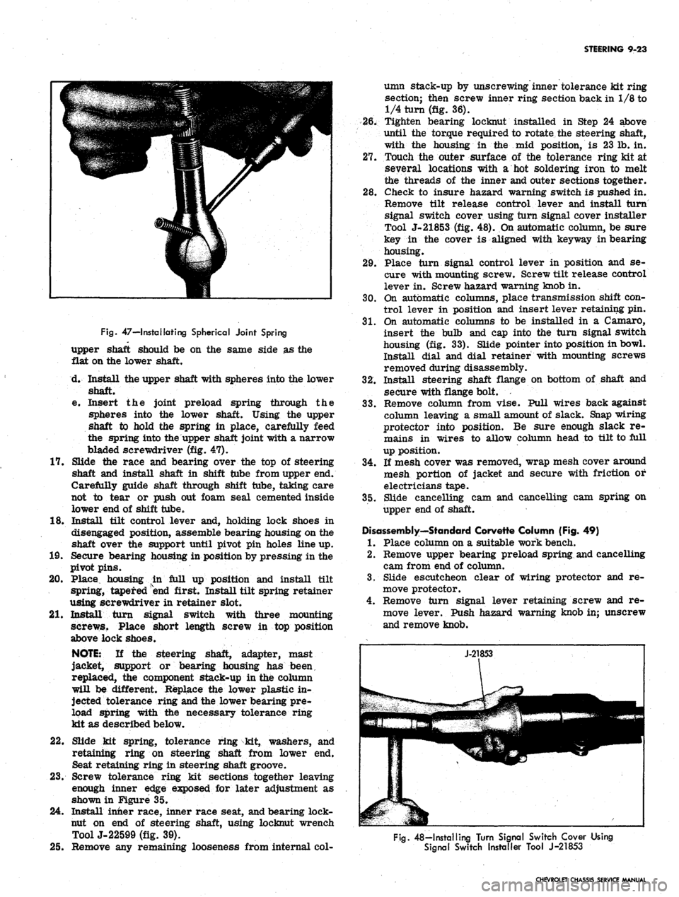
Fig.
47—I retaliating Spherical Joint Spring
upper shaft should be on the same side as the
flat on the lower shaft.
d. Install the upper shaft with spheres into the lower
shaft.
e. Insert the joint preload spring through the
spheres into the lower shaft. Using the upper
shaft to hold the spring in place, carefully feed
the spring into the upper shaft joint with a narrow
bladed screwdriver (fig. 47).
17.
Slide the race and bearing over the top of steering
shaft and install shaft in shift tube from upper end.
Carefully guide shaft through shift tube, taking care
not to tear or push out foam seal cemented inside
lower end of shift tube.
18.
Install tilt control lever and, holding lock shoes in
disengaged position, assemble bearing housing on the
shaft over the support until pivot pin holes line up.
19.
Secure bearing housing in position by pressing in the
pivot pins.
20.
Place housing in full up position and install tilt
spring, tapered end first. Install tilt spring retainer
using screwdriver in retainer slot.
21.
Install turn signal switch with three mounting
screws. Place short length screw in top position
above lock shoes.
NOTE:
If the steering shaft, adapter, mast
jacket, support or bearing housing has been,
replaced, the component stack-up in the column
will be different. Replace the lower plastic in-
jected tolerance ring and the lower bearing pre-
load spring with the necessary tolerance ring
kit as described below.
22.
Slide kit spring, tolerance ring kit, washers, and
retaining ring on steering shaft from lower end.
Seat retaining ring in steering shaft groove.
23.
Screw tolerance ring kit sections together leaving
enough inner edge exposed for later adjustment as
shown in Figure 35.
24.
Install inner race, inner race seat, and bearing lock-
nut on end of steering shaft, using locknut wrench
ToolJ-22599 (fig. 39).
25.
Remove any remaining looseness from internal col-
umn stack-up by unscrewing inner tolerance kit ring
section; then screw inner ring section back in 1/8 to
1/4 turn (fig. 36).
26.
Tighten bearing locknut installed in Step 24 above
until the torque required to rotate the steering shaft,
with the housing in the mid position, is 23 lb. in.
27.
Touch the outer surface of the tolerance ring kit at
several locations with a hot soldering iron to melt
the threads of the inner and outer sections together.
28.
Check to insure hazard warning switch is pushed in.
Remove tilt release control lever and install turn
signal switch cover using turn signal cover installer
Tool J-21853 (fig. 48). On automatic column, be sure
key in the cover is aligned with keyway in bearing
housing.
29.
Place turn signal control lever in position and se-
cure with mounting screw. Screw tilt release control
lever in. Screw hazard warning knob in.
30.
On automatic columns, place transmission shift con-
trol lever in position and insert lever retaining pin.
31.
On automatic columns to be installed in a Camaro,
insert the bulb and cap into the turn signal switch
housing (fig. 33). Slide pointer into position in bowl.
Install dial and dial retainer with mounting screws
removed during disassembly.
32.
Install steering shaft flange on bottom of shaft and
secure with flange bolt.
33.
Remove column from vise. Pull wires back against
column leaving a small amount of slack. Snap wiring
protector into position. Be sure enough slack re-
mains in wires to allow column head to tilt to full
up position.
34.
If mesh cover was removed, wrap mesh cover around
mesh portion of jacket and secure with friction or
electricians tape.
35.
Slide cancelling cam and cancelling cam spring on
upper end of shaft.
Disassembly—Standard Corvette Column (Fig. 49)
1.
Place column on a suitable work bench.
2.
Remove upper bearing preload spring and cancelling
cam from end of column.
3.
Slide escutcheon clear of wiring protector and re-
move protector.
4.
Remove turn signal lever retaining screw and re-
move lever. Push hazard warning knob in; unscrew
and remove knob.
Fig.
48—Installing Turn Signal Switch Cover Using
Signal Switch Installer Tool J-21853
CHEVROLET CHASSIS SERVICE MANUAL
Page 464 of 659
STEERING
9-24
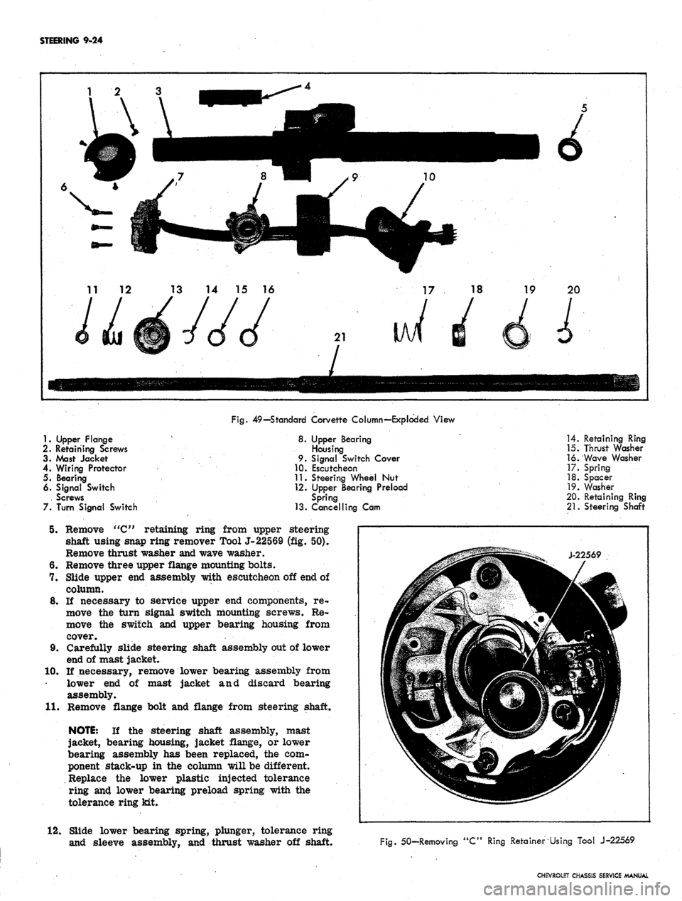
1.
Upper Flange
2.
Retaining Screws
3.
Mast Jacket
4.
Wiring Protector
5. Bearing
6. Signal Switch
. Screws
7.
Turn Signal Switch
Fig.
49—Standard Corvette Column—Exploded View
8.
Upper Bearing
Housing
9.
Signal Switch Cover
10.
Escutcheon
11.
Steering Wheel Nut
12.
Upper Bearing Preload
Spring
13.
Cancelling Cam
5. Remove "C" retaining ring from upper steering
shaft using snap ring remover Tool J-22569 (fig. 50).
Remove thrust washer and wave washer.
6. Remove three upper flange mounting bolts.
7. Slide upper end assembly with escutcheon off end of
column.
8. If necessary to service upper end components, re-
move the turn signal switch mounting screws. Re-
move the switch and upper bearing housing from
cover.
9. Carefully slide steering shaft assembly out of lower
end of mast jacket.
10.
If necessary, remove lower bearing assembly from
lower end of mast jacket and discard bearing
assembly.
11.
Remove flange bolt and flange from steering shaft.
NOTE:
If the steering shaft assembly, mast
jacket, bearing housing, jacket flange, or lower
bearing assembly has been replaced, the com-
ponent stack-up in the column will be different.
Replace the lower plastic injected tolerance
ring an4 lower bearing preload spring with the
tolerance ring kit.
12.
Slide lower bearing spring, plunger, tolerance ring
and sleeve assembly, and thrust washer off shaft.
14.
Retaining Ring
15.
Thrust Washer
16.
Wave Washer
17.
Spring
18.
Spacer
19.
Washer
20.
Retaining Ring
21.
Steering Shaft
Fig.
50-Removing "C" Ring Retainer Using Tool J-22569
CHEVROLET CHASSIS SERVICE MANUAL
Page 465 of 659
STEERING 9-25
\
£$&+
SIGNAL SWITCH
^ ^-BEARING
UPPER FLANGE^
HOUSING
COVER
»,
ESCUTCHEON
"^^^^^fr
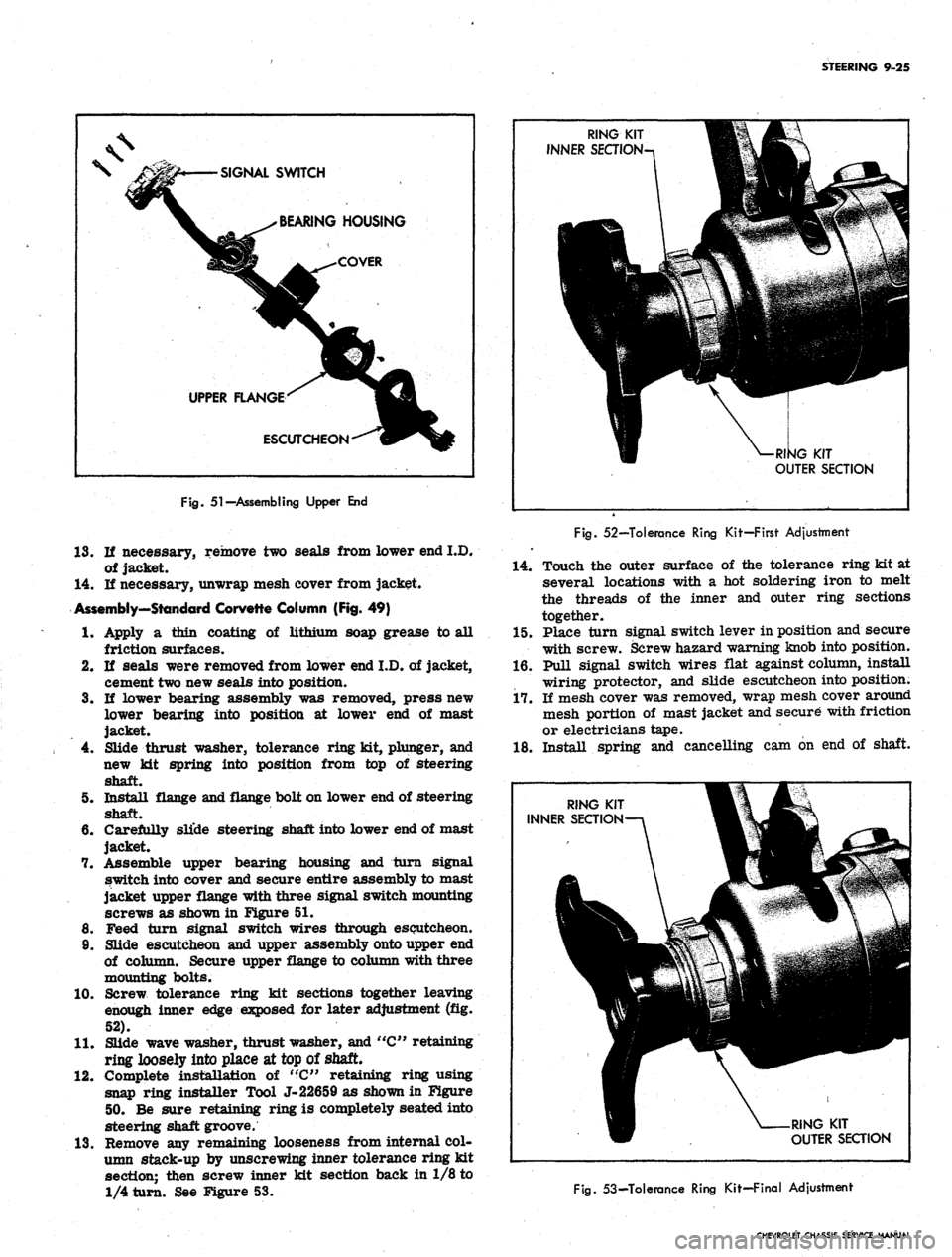
Fig.
51-Assembling Upper End
13.
If necessary, remove two seals from lower end I.D.
of jacket.
14.
If necessary, unwrap mesh cover from jacket.
Assembly—Standard Corvette Column (Fig. 49)
RING KIT V
INNER SEaiON-n 1
\
[1
3
^^•-
'^p|§
W- - V: -: ';'^ /
W ^-RI^G KIT
OUTER SECTION
Fig.
52—Tolerance Ring Kit—First Adjustment
14.
Touch the outer surface of the tolerance ring kit at
several locations with a hot soldering iron to melt
the threads of the inner and outer ring sections
together.
1.
4.
5.
6.
of lithium soap grease to all 15. Place turn signal switch lever in position and secure
10.
11.
12.
13.
Apply a thin coating
friction surfaces.
If seals were removed from lower end I.D. of jacket,
cement two new seals into position.
If lower bearing assembly was removed, press new
lower bearing into position at lower end of mast
jacket.
Slide thrust washer, tolerance ring kit, plunger, and
new kit spring into position from top of steering
shaft.
Install flange and flange bolt on lower end of steering
shaft.
Carefully slide steering shaft into lower end of mast
jacket.
Assemble upper bearing housing and turn signal
switch into cover and secure entire assembly to mast
jacket upper flange with three signal switch mounting
screws as shown in Figure 51.
Feed turn signal switch wires through escutcheon.
Slide escutcheon and upper assembly onto upper end
of column. Secure upper flange to column with three
mounting bolts.
Screw tolerance ring kit sections together leaving
enough inner edge exposed for later adjustment (fig.
52).
Slide wave washer, thrust washer, and "C" retaining
ring loosely into place at top of shaft.
Complete installation of "C" retaining ring using
snap ring installer Tool J-22659 as shown in Figure
50.
Be sure retaining ring is completely seated into
steering shaft groove.
Remove any remaining looseness from internal col-
umn stack-up by unscrewing inner tolerance ring kit
section; then screw inner kit section back in 1/8 to
1/4 turn. See Figure 53.
with screw. Screw hazard warning knob into position.
16.
Pull signal switch wires flat against column, install
wiring protector, and slide escutcheon into position.
17.
If mesh cover was removed, wrap mesh cover around
mesh portion of mast jacket and secure with friction
or electricians tape.
18.
Install spring and cancelling cam on end of shaft.
RING KIT
OUTER SECTION
fig.
53-Tolerance Ring Kit-Final Adjustment
CHEVROLET CHASSIS SERVICE MANUAL
Page 466 of 659

STEERING
9-26
Fig.
54—Corvette Telescoping Column—Exploded View
1.
Wiring Protector
2.
Screw
3. Screw
4. Turn Signal Switch
5. Upper Bearing
Housing
6. Signal Switch Cover
7. Escutcheon
8
9
10
11
12
13
14
8.
Mast Jacket
9. Bumper
Key
Bumper
Bumper Key Strap
Steering Wheel Nut
Upper Bearing Preload
Spring
15.
Cancelling Cam
16.
Retaining Ring
17.
Thrust Washer
18.
Wave Washer
19.
Retainer
20.
Bearing
21.
Spring
22.
Washer
23. Retaining Ring
24.
Lower Steering
Shaft
25.
Upper Steering
Shaft
26.
Locking
Rod
27.
Wedge
Disassembly—Corvette Telescoping Column (Fig. 54).
1.
Place column on a suitable work bench.,
2.
Remove upper bearing preload spring and cancelling
cam from end of shaft.
3.
Remove turn signal lever retaining screw and re-
move lever. Push hazard warning knob in; unscrew
and remove knob.
4.
Remove upper retaining ring from upper steering
shaft using a screwdriver. Remove thrust washer
and wave washer. -
5. Remove three- screws from the lower bearing
retainer.
6. Carefully slide steering shaft assembly out of lower
end of mast jacket.
7. Remove flange bolt and flange from lower end of
shaft. -
CAUTION: Use caution when removing the low-
er retaining ring in the following step. The lower
bearing washer is under load from the com-
pressed spring and could cause injury when the
lower retaining ring is removed.
8. Carefully remove lower retaining ring as shown in
Figure 55. Remove washer* spring, packing, and
CHEVROLET CHASSIS SERVICE MANUAL
Page 467 of 659

STEERING 9-27
Fig.
55— Removing Lower Bearing Retaining Ring
bearing assembly from lower end of shaft.
9. Push upper steering shaft section into lower section
until spring pin is visible at pin access hole in lower
section. Drive out spring pin.
10.
Remove upper shaft section from lower section. If
necessary, replace locking wedge and locking rod at
this time.
11.
Remove bumper key strap (fig. 56). Remove keys and
bumper assembly.
12.
Remove screws securing bottom of wiring protector
to column.
13.
Slide inner jacket section, switch cover, switch,
upper bearing housing, wiring protector, and es-
cutcheon off top end of jacket.
14.
If necessary, remove three turn signal switch mount-
ing screws and remove switch and upper bearing
housing.
15.
If necessary, remove seals from I.D. of mast jacket.
16.
If necessary, unwrap mesh cover from jacket.
Assembly—Corvette Telescoping Column (Fig. 54)
1.
Apply a thin coating of lithium soap grease to all
friction surfaces.
2.
If seals were removed from I.D. of mast jacket,
cement new seals in positions where old seals were
removed.
3.
Place locking wedge and locking rod into upper shaft
and slide upper shaft into lower shaft.
4.
Align upper and lower shafts and insert spring pin
into access hole.
5. Install bearing, packing, spring, washer, and retain-
ing ring on bottom of steering shaft. Seat the re-
taining ring into the steering shaft groove with a
screwdriver.
6. Carefully slide steering shaft into lower end of mast
jacket.
7. Install bearing retainer over lower end of shaft and
lower end of jacket. Secure retainer with three
screws.
8. Install flange and flange bolt on lower end of steering
shaft.
9. Feed wires of turn signal switch through turn signal
switch cover and escutcheon, and place switch and
upper bearing housing in cover. Secure switch to
cover with three mounting screws.
10.
Place wiring protector inside escutcheon.
11.
Start escutcheon and wiring protector, with signal
switch wires, over end of outer jacket.
12.
Slide inner jacket section into outer jacket section.
13.
Secure switch cover to flange of inner jacket section
by tightening the signal switch mounting screws.
14.
Secure the bottom of the wiring protector to the col-
umn with two screws.
15.
Assemble keys and bumper and place the entire as-
sembly in position in the jacket. Install bumper key
strap.
16.
Slide wave washer, thrust washer, and upper retain-
ing ring into place at top of shaft. Seat retaining ring
in steering shaft groove with a screwdriver.
17.
Place turn signal switch lever in position and secure
with screw. Screw hazard warning knob into position.
18.
If mesh cover was removed, wrap mesh cover around
mesh section of jacket and secure with electricians
or friction tape.
19.
Slide cancelling cam and upper bearing preload
spring over top end of shaft.
Installation
NOTE:
Before placing column in position in
vehicle, refer to figures 19 through 23 and slide
dash panel seals, covers, plates, and clamps
loosely into position on column for later
installation.
1.
Move front seat back as far as possible to provide
Fig.
56—Removing Bumper Key Strap
CHEVROLET CHASSIS SERVICE MANUAL
Page 468 of 659
STEERING 9-28
WEDGE SHIM
2.
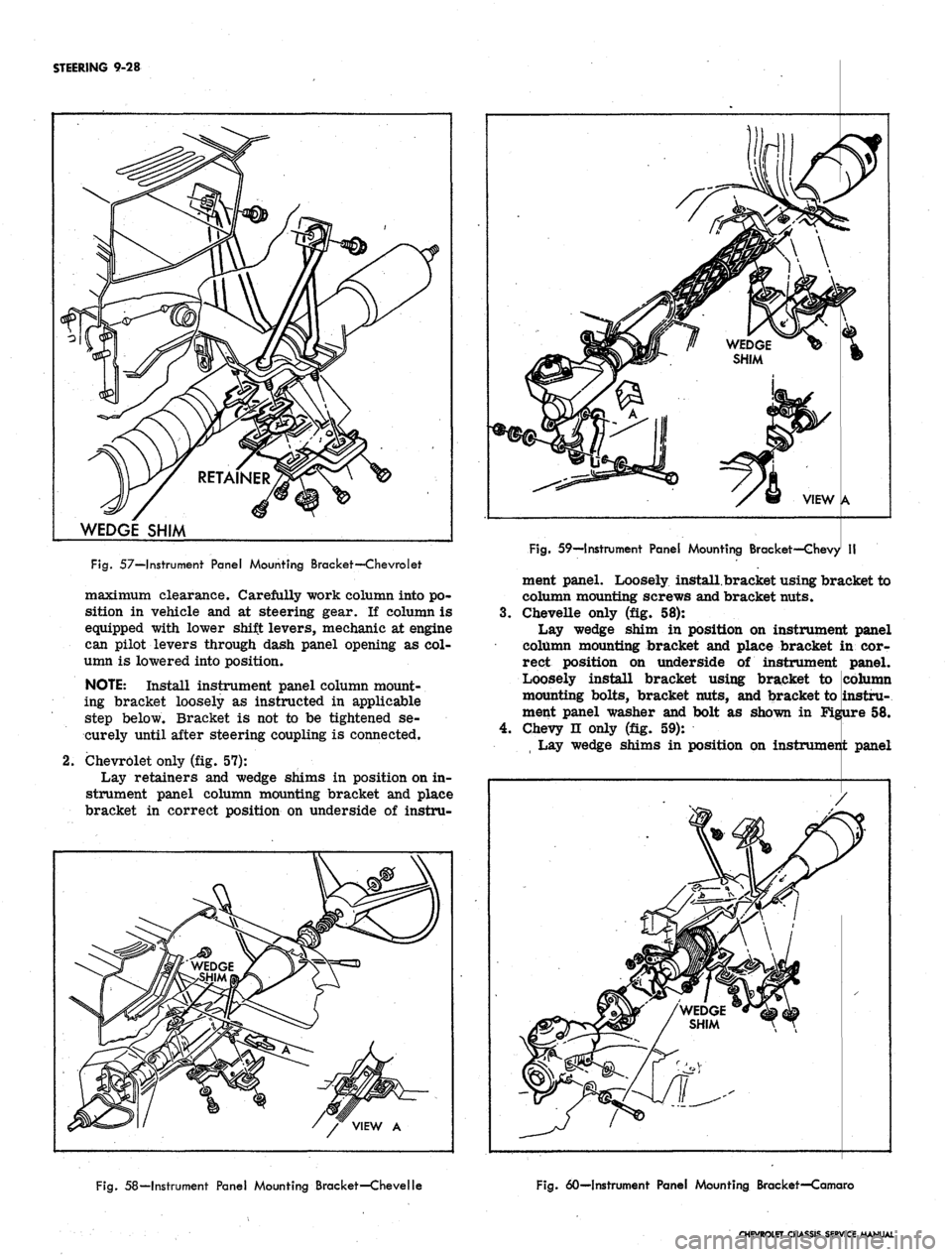
Fig.
57—Instrument Panel Mounting Bracket—Chevrolet
maximum clearance. Carefully work column into po-
sition in vehicle and at steering gear. If column is
equipped with lower shift levers, mechanic at engine
can pilot levers through dash panel opening as col-
umn is lowered into position.
NOTE:
Install instrument panel column mount-
ing bracket loosely as instructed in applicable
step below. Bracket is not to be tightened se-
curely until after steering coupling is connected.
Chevrolet only (fig. 57):
Lay retainers and wedge shims in position on in-
strument panel column mounting bracket and place
bracket in correct position on underside of instru-
3.
4.
Fig.
59—Instrument Panel Mounting Bracket—Chevy
ment panel. Loosely install.bracket using bracket to
column mounting screws and bracket nuts.
Chevelle only (fig. 58):
Lay wedge shim in position on instrument
column mounting bracket and place bracket
rect position on underside of instrument
Loosely install bracket using bracket to
mounting bolts, bracket nuts, and bracket to
ment panel washer and bolt as shown in
Chevy n only (fig. 59):
Lay wedge shims in position on instrument
Fig.
58—Instrument Panel Mounting Bracket—Chevelle
Fig.
60—Instrument Panel Mounting Bracket—Comoro
CHEVROLET CHASSIS SERVICE MANUAL
panel
in cor-
panel.
column
instru-
58.
Figure
panel
Page 469 of 659

STEERING 9-29
column mounting bracket, and place bracket in cor-
rect position on underside of instrument panel.
Loosely install bracket using bracket to column
mounting screws and bracket to instrument panel
washers and bolts.
NOTE: Steering shaft to gear clamp must be
tightened before column attaching bolts are
torqued. Refer to "Steering Gear-Chevy n",
installation procedure, for correct Chevy II
steering column alignment procedure.
5.
Camaro only (fig. 60):
Lay wedge shim in position on instrument panel
column mounting bracket and place bracket in cor-
rect position on underside of instrument panel.
Loosely install bracket using bracket to column
mounting screws, nuts, and washer and bolt as shown
in Figure 60.
6. Corvette only (fig. 61):
Loosely secure column mounting bracket to sup-
port plate and instrument panel with washers and
bolts.
7.
Secure flanged end of column to steering coupling
with lockwashers and nuts. On Chevy n, connect col-
umn to steering gear with clamp, clamp bolt, and
nut. On Corvette, slide steering shaft flange into
lower coupling
half,
and install upper clamp bolt
loosely; also secure support, seal and clamp loosely
at dash on engine side.
8. Tighten instrument panel mounting bracket bolts and
nuts.
Refer to torque specifications at rear of manual
for correct torque values.
9. Chevrolet only (fig. 15):
Place upper and lower mast jacket covers in po-
sition and secure covers together and to instrument
panel using nuts and screws as shown in Figure 15.
10.
Chevy H only (fig. 18):
Place lower mast jacket cover in position under
mast jacket and secure to upper cover with screws.
11.
CheveUe only (fig. 15):
Place mast jacket trim cover in position over col-
Fig.
61—Instrument Panel Mounting Bracket and
Support Plqte—Corvette
umn on underside of instrument panel and secure
with screws.
12.
Corvette only (fig. 14):
Slide escutcheon into position at instrument panel
and secure with screws. Place upper end lower
covers in position and secure with screws.
13.
On Chevrolet and CheveUe models with column
mounted powerglide controls, secure transmission
shift indicator pointer into position with set screw
(fig. 15). ,
14.
Chevrolet only (fig. 19):
a. Secure seal and cover to dash panel with screws.
b.
Place clamp assembly in position and install
clamp screw.
c. Install dash panel trim cover with mounting
screws.
15.
Chevelle only (fig. 20):
a. Secure seal and inner and outer covers to dash
panel with screws.
b.
Secure inner and outer covers together with
screws.
c. Install trim cover to dash panel with two
retainers.
16.
Chevy H only (fig. 21):
a. Secure seal, retainer, and clamp to dash panel
with screws.
b.
Install clamp screw.
c. Slide collar into position. Pinch and staple upper
tabs together.
17.
Camaro only (fig. 22):
a. Secure seal, upper cover, and lower cover to
dash panel with screws.
b.
Secure upper and lower cover together with
screws.
c. Fold rubber boot over securely against dash panel
to conceal covers.
18.
Corvette only (fig. 23):
a. Secure seal and support assembly to dash panel
on engine compartment side.
b.
Tighten clamp, washer, and clamp bolt on engine
compartment side.
19.
Connect transmission linkage to lower shift tube
levers in engine compartment, if column is so
equipped. Adjust levers as outlined in Section 7.
20.
Install steering wheel as outlined in this section.
21.
Connect directional signal, horn, back-up lamp, and
neutral start switch at wiring harness plugs. Adjust
back-up lamp, neutral start switch as outlined in
Section 12.
22.
Adjust steering gear and align and center steering
wheel as outlined in this section.
STEERING LINKAGE (Fig. 62)
TIE RODS
There are two tie rod assemblies used on all models.
Each assembly is of three piece construction, consisting
of a sleeve and two tie rod ends. The ends are threaded
into the sleeve and locked with clamps. Right and left
hand threads are provided to facilitate toe-in adjustment
and steering gear centering.
The tie rod ends are self-adjusting for wear and re-
quire no attention in service other than periodic lubrica-
tion and occasional inspection to see that ball studs are
tight. Replacement of tie rod ends should be made when
CHEVROLET CHASSIS SERVICE MANUAL
Page 470 of 659

STEERING 9-30
CHEVROLET
CHEVELLE
CHEVII
CAMARO
CORVETTE
Fig.
62—Steering Linkage
excessive up and down motion is evident or if any lost
motion or end play at ball end of stud exists.
Removal
1.
Remove cotter pins from ball studs and remove
castellated nuts.
2.
To remove outer ball stud, tap on steering arm at
tie rod end with a hammer while using a heavy
hammer or similar tool as a backing (Fig. 63). If
necessary pull downward on tie rod to remove from
steering arm.
3.
Remove inner ball stud from relay rod using same
procedure as described in Step 2.
4.
To remove tie rod ends from tie rods loosen clamp
bolts and unscrew end assemblies.
Installation
1.
If the tie rod ends were removed, lubricate the tie
CHEVROLET CHASSIS SERVICE MANUAL