CHEVROLET CAMARO 1967 1.G Chassis Manual Online
Manufacturer: CHEVROLET, Model Year: 1967, Model line: CAMARO, Model: CHEVROLET CAMARO 1967 1.GPages: 659, PDF Size: 114.24 MB
Page 81 of 659
HEATER AND AIR CONDITIONING 1A-58
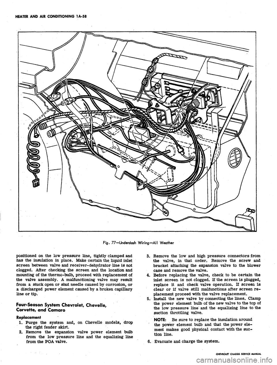
Fig.
77-Underdash Wiring-All Weather
positioned on the low pressure line, tightly clamped and
has the insulation in place. Make certain the liquid inlet
screen between valve and receiver- dehydrator line is not
clogged. After checking the screen and the location and
mounting of the thermo-bulb, proceed with replacement of
the valve assembly. A malfunctioning valve may result
from a stuck open or shut needle caused by corrosion^ or
a discharged power element caused by a broken capillary
line or tip.
Four-Season System Chevrolet, Chevelle,
Corvette, and Camaro
Replacement
1.
Purge the system and, on Chevelle models, drop
the right fender skirt.
2.
Remove the expansion valve power element bulb
from the low pressure line and the equalizing line
from the POA valve.
3.
Remove the low and high pressure connectors from
the valve, in that order. Remove the screw and
bracket attaching the expansion valve to the blower
case and remove the valve.
4.
Before replacing the valve, check to be certain the
inlet screen, is not clogged. If the screen is plugged,
replace it and check valve operation. If screen is
clear or if valve still malfunctions after screen re-
placement proceed with the valve replacement.
5. Install the new valve by connecting the lines. Clamp
the power element bulb of the new valve to the top of
the low pressure line and the equalizing line to the
suction throttling valve.
NOTE:
Be sure to replace the insulation around
the power element bulb and that the power ele-
ment makes good physical contact with the suc-
tion line.
6. Evacuate and charge the system.
CHEVROLET CHASSIS SERVICE MANUAL
Page 82 of 659
HEATER AND AIR CONDITIONING 1A-59
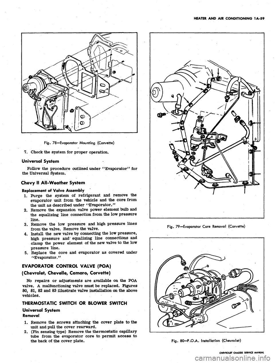
Fig.
78—Evaporator Mounting (Corvette)
7. Check the system for proper operation.
Universal System
Follow the procedure outlined under " Evaporator" for
the Universal System.
Chevy II All-Weather System
Replacement of Valve Assembly
1.
Purge the system of refrigerant and remove the
evaporator unit from the vehicle and the core from
the unit as described under "Evaporator."
2.
Remove the expansion valve power element bulb and
the equalizing line connection from the low pressure
line.
3.
Remove the low pressure and high pressure lines
from the valve. Remove the valve.
4.
Install the new valve by connecting the low pressure,
high pressure and* equalizing line connections and
clamp the power element of the new valve to the low
pressure line.
5. Replace the core and evaporator as covered under
"Evaporator."
EVAPORATOR CONTROL VALVE (POA)
(Chevrolet, Chevelle, Comoro, Corvette)
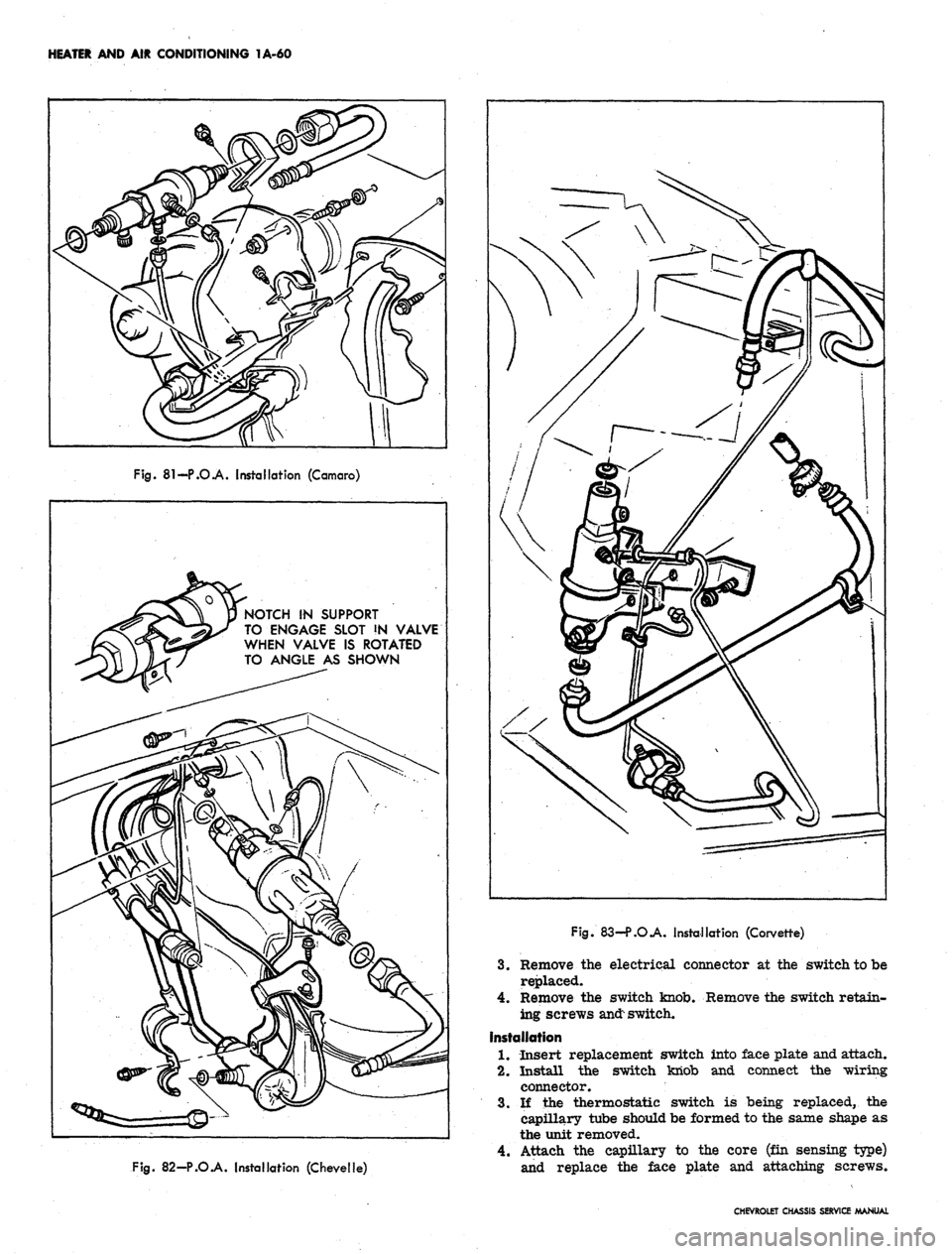
No repairs or adjustments are available on the POA
valve. A malfunctioning valve must be replaced. Figures
80,
81, 82 and 83 illustrate valve installation on the above
vehicles.
THERMOSTATIC SWITCH OR BLOWER SWITCH
Universal System
Removal
1.
Remove the screws attaching the cover plate to the
unit and pull the cover rearward.
2.
(Fin sensing type) Remove the thermostatic capillary
tube from the evaporator core to permit access to
the back of the cover plate.
Fig.
79—Evaporator Core Removal (Corvette)
Fig.
80-P.O.A. Installation (Chevrolet)
CHEVROLET CHASSIS SERVICE MANUAL
Page 83 of 659
HEATER AND AIR CONDITIONING 1A-60
Fig.
81-P.O.A. Installation (Camaro)
NOTCH IN SUPPORT
TO ENGAGE SLOT !N VALVE
WHEN VALVE IS ROTATED
TO ANGLE AS SHOWN
Fig.
82-P.O.A. Installation (Chevelle)
Fig.
83—P.O.A. Installation (Corvette)
3.
Remove the electrical connector at the switch to be
replaced.
4.
Remove the switch knob. Remove the switch retain-
ing screws
and:
switch.
Installation
1.
Insert replacement switch into face plate and attach.
2.
Install the switch knob and connect the wiring
connector.
3.
If the thermostatic switch is being replaced, the
capillary tube should be formed to the same shape as
the unit removed.
4.
Attach the capillary to the core (fin sensing type)
and replace the face plate and attaching screws.
CHEVROLET CHASSIS SERVICE MANUAL
Page 84 of 659
HEATER AND AIR CONDITIONING 1A-61
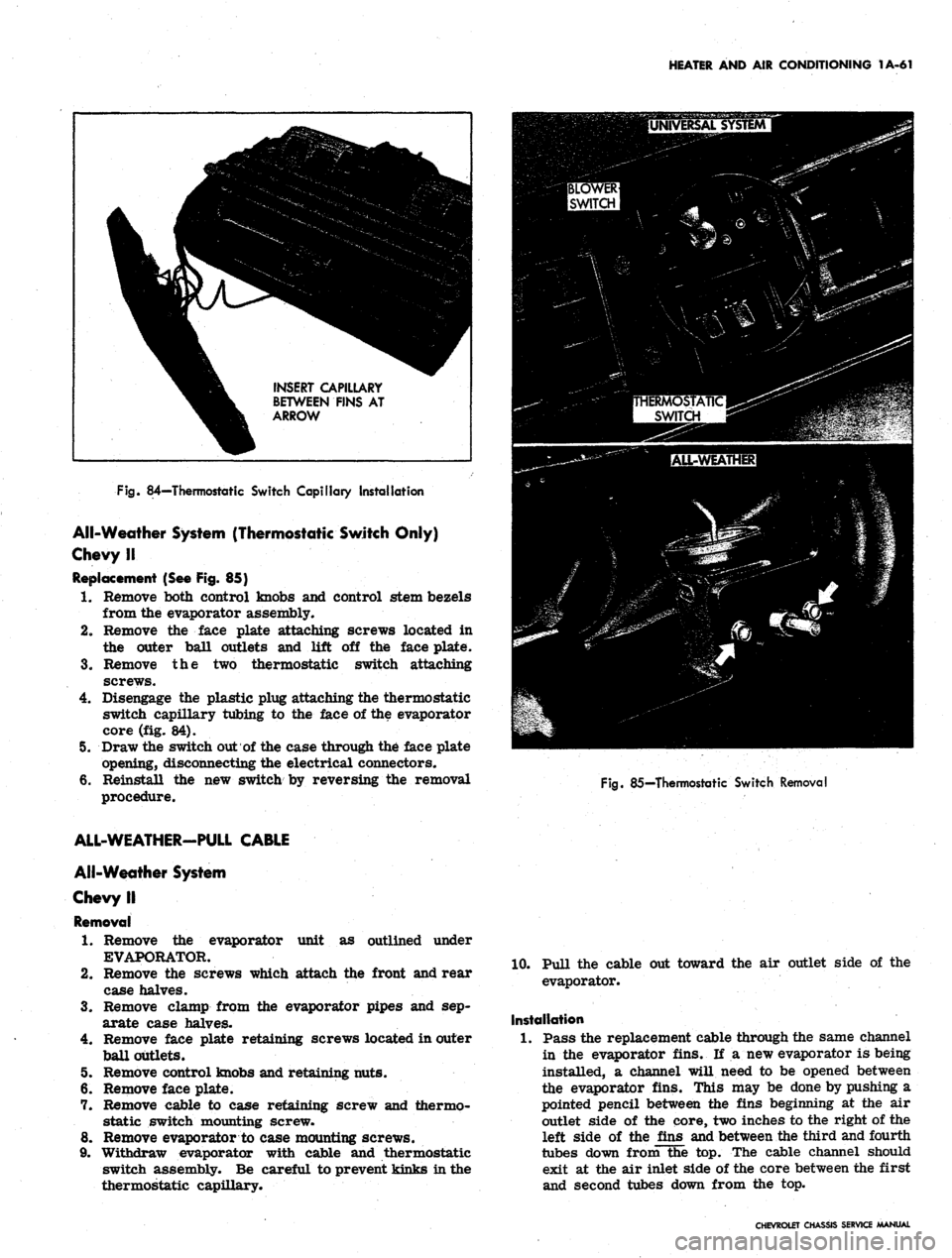
INSERT CAPILLARY
BETWEEN FINS AT
ARROW
Fig.
84—Thermostatic Switch Capillary Installation
All-Weather System (Thermostatic Switch Only)
Chevy II
Replacement (See Fig. 85)
1.
Remove both control knobs and control stem bezels
from the evaporator assembly.
2.
Remove the face plate attaching screws located in
the outer ball outlets and lift off the face plate.
3.
Remove the two thermostatic switch attaching
screws.
4.
Disengage the plastic plug attaching the thermostatic
switch capillary tubing to the face of the evaporator
core (fig. 84).
5. Draw the switch out of the case through the face plate
opening, disconnecting the electrical connectors.
6. Reinstall the new switch by reversing the removal
procedure.
Fig.
85—Thermostatic Switch Removal
unit as outlined under
ALL-WEATHER-PULL CABLE
All-Weather System
Chevy II
Removal
1.
Remove the evaporator
EVAPORATOR.
2.
Remove the screws which attach the front and rear
case halves.
3.
Remove clamp from the evaporator pipes and sep-
arate case halves.
4.
Remove face plate retaining screws located in outer
ball outlets.
5. Remove control knobs and retaining nuts.
6. Remove face plate.
7. Remove cable to case retaining screw and thermo-
static switch mounting screw.
8. Remove evaporator to case mounting screws.
9. Withdraw evaporator with cable and thermostatic
switch assembly. Be careful to prevent kinks in the
thermostatic capillary.
10.
Pull the cable out toward the air outlet side of the
evaporator.
Installation
1.
Pass the replacement cable through the same channel
in the evaporator fins. If a new evaporator is being
installed, a channel will need to be opened between
the evaporator fins. This may be done by pushing a
pointed pencil between the fins beginning at the air
outlet side of the core, two inches to the right of the
left side of the fins and between the third and fourth
tubes down from the top. The cable channel should
exit at the air inlet side of the core between the first
and second tubes down from the top.
CHEVROLET CHASSIS SERVICE MANUAL
Page 85 of 659
HEATER AND AIR CONDITIONING 1A-62
2.
Insert the evaporator assembly into the outlet case
half and mount the evaporator, thermostatic switch,
and cable to the case.
3.
Install the face plate to the case and install control
retaining nuts and knobs.
4.
Assemble the case halves and mount the evaporator
pipe clamp.
5. Install the evaporator assembly as previously
described under EVAPORATOR.
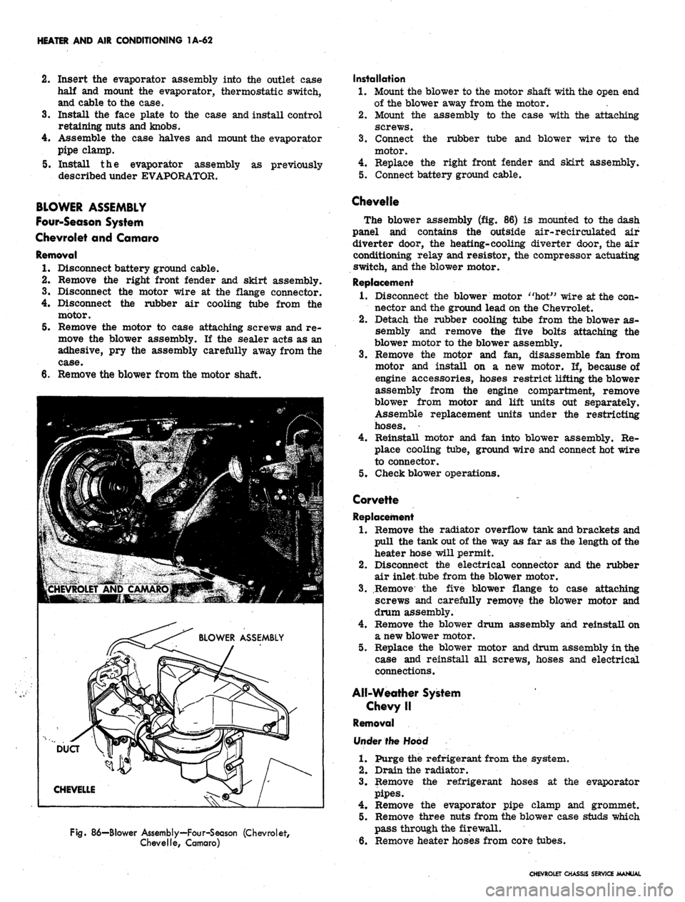
BLOWER ASSEMBLY
Four-Season System
Chevrolet and Camaro
Removal
1.
Disconnect battery ground cable.
2.
Remove the right front fender and skirt assembly.
3.
Disconnect the motor wire at the flange connector.
4.
Disconnect the rubber air cooling tube from the
motor.
5. Remove the motor to case attaching screws and re-
move the blower assembly. If the sealer acts as an
adhesive, pry the assembly carefully away from the
6. Remove the blower from the motor shaft.
Fig.
86—Blower Assembly—Four-Season (Chevrolet,
Chevelle, Camaro)
Installation
1.
Mount the blower to the motor shaft with the open end
of the blower away from the motor.
2.
Mount the assembly to the case with the attaching
screws.
3.
Connect the rubber tube and blower wire to the
motor.
4.
Replace the right front fender and skirt assembly.
5. Connect battery ground cable.
Chevelle
The blower assembly (fig. 86) is mounted to the dash
panel and contains the outside air-recirculated air
diverter door, the heating-cooling diverter door, the air
conditioning relay and resistor, the compressor actuating
switch, and the blower motor.
Replacement
1.
Disconnect the blower motor "hot" wire at the con-
nector and the ground lead on the Chevrolet.
2.
Detach the rubber cooling tube from the blower as-
sembly and remove the five bolts attaching the
blower motor to the blower assembly.
3.
Remove the motor and fan, disassemble fan from
motor and install on a new motor. If, because of
engine accessories, hoses restrict lifting the blower
assembly from the engine compartment, remove
blower from motor and lift units out separately.
Assemble replacement units under the restricting
hoses.
4.
Reinstall motor and fan into blower assembly. Re-
place cooling tube, ground wire and connect hot wire
to connector.
5. Check blower operations.
Corvette
Replacement
1.
Remove the radiator overflow tank and brackets and
pull the tank out of the way as far as the length of the
heater hose will permit.
2.
Disconnect the electrical connector and the rubber
air inlet tube from the blower motor.
3.
Remove the five blower flange to case attaching
screws and carefully remove the blower motor and
drum assembly.
4.
Remove the blower drum assembly and reinstall on
a new blower motor.
5. Replace the blower motor and drum assembly in the
case and reinstall all screws, hoses and electrical
connections.
All-Weather System
Chevy II
Removal
Under the Hood
1.
Purge the refrigerant from the system.
2.
Drain the radiator.
3.
Remove the refrigerant hoses at the evaporator
pipes.
4.
Remove the evaporator pipe clamp and grommet.
5. Remove three nuts from the blower case studs which
pass through the firewall.
6. Remove heater hoses from core tubes.
CHEVROLET CHASSIS SERVICE MANUAL
Page 86 of 659
HEATER AND AIR CONDITIONING 1A-63
Under Dash
7. Remove ash tray and retainer, and glove box.
8. Remove blower case to air inlet adapter bracket
retaining screw.
9. Remove screw attaching air distributor to firewall.
10.
Remove nuts retaining evaporator case to lower lip
of dash. Withdraw evaporator drain tubes.
11.
Lower complete heater - air conditioning assembly.
12.
Remove screw retaining blower case to air distrib-
utor and separate them.
13.
Remove blower to case attaching screws. Disconnect
motor wire and remove blower assembly.
14.
Remove blower from motor shaft.
Installation
1.
Assemble blower to motor shaft.
2.
Mount motor in blower case and connect wire.
3.
Assemble blower case to air distributor and install
retaining screw.
4.
Lift the complete assembly into place and install
attaching screws and nuts.
5. Replace ash tray retainer and tray and glove box.
6. Replace nuts (engine side of dash) on heater case
studs and connect heater hoses.
7. Replace evaporator pipe clamp and grommet.
8. Replace the refrigerant hoses.
9. Evacuate and charge the refrigeration system and
refill the cooling system.
10.
Check system performance.
Universal Blower Assembly
Removal
1.
Remove the universal unit from its dash mounts.
2.
Remove the cover plate and separate the upper and
lower case halves. Remove blower motor mounting
strap screw and swing strap outward.
3.
Remove blower assembly. Loosen the blower wheel
setscrews and remove the wheels from the motor
shaft. . ' .
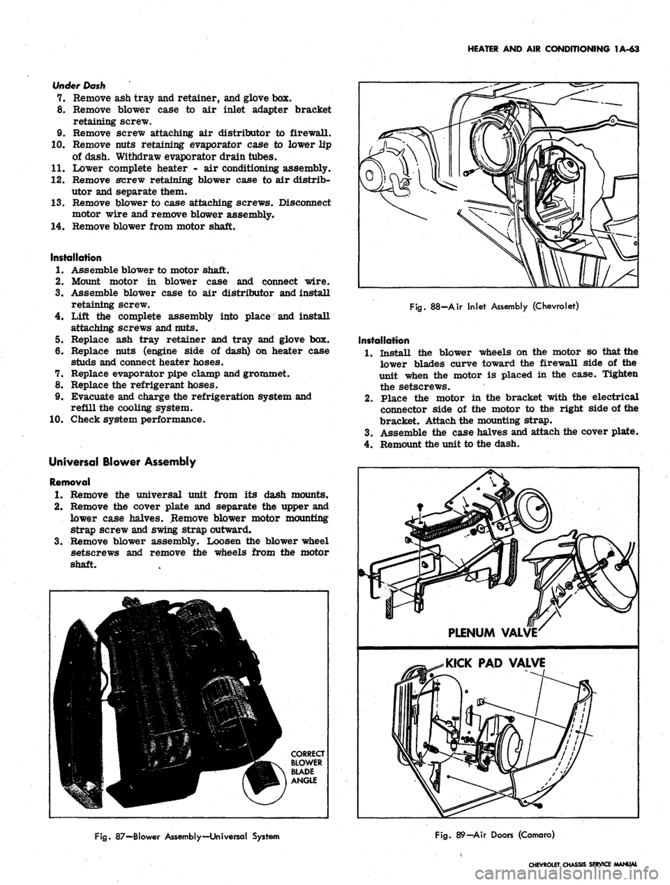
Fig.
88-Air Inlet Assembly (Chevrolet)
Installation
1.
Install the blower wheels on the motor so that the
lower blades curve toward the firewall side of the
unit when the motor is placed in the case. Tighten
the setscrews.
2.
Place the motor in the bracket with the electrical
connector side of the motor to the right side of the
bracket. Attach the mounting strap.
3.
Assemble the case halves and attach the cover plate.
4.
Remount the unit to the dash.
Fig.
87—Blower Assembly—Universal System
Fig.
89—Air Doors (Camaro)
CHEVROLET CHASSIS SERVICE
Page 87 of 659
HEATER AND AIR CONDITIONING 1A-64
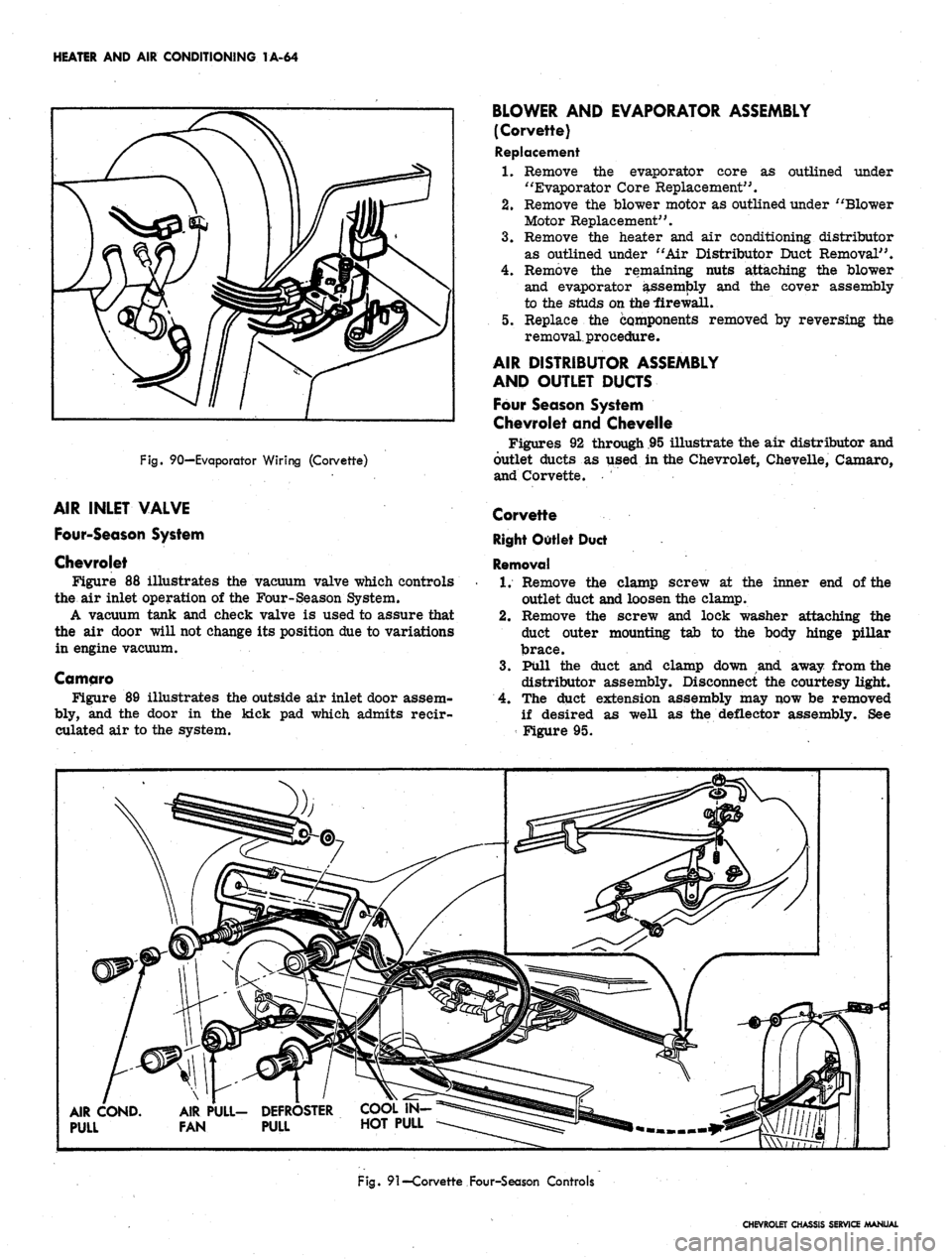
Fig.
90—Evaporator Wiring (Corvette)
AIR INLET VALVE
Four-Season System
Chevrolet
Figure 88 illustrates the vacuum valve which controls
the air inlet operation of the Four-Season System.
A vacuum tank and check valve is used to assure that
the air door will not change its position due to variations
in engine vacuum.
Camqro
Figure 89 illustrates the outside air inlet door assem-
bly, and the door in the kick pad which admits reeir-
culated air to the system.
BLOWER AND EVAPORATOR ASSEMBLY
(Corvette)
Replacement
1.
Remove the evaporator core as outlined under
"Evaporator Core Replacement".
2.
Remove the blower motor as outlined under "Blower
Motor Replacement".
3.
Remove the heater and air conditioning distributor
as outlined under "Air Distributor Duct Removal".
4.
Remove the remaining nuts attaching the blower
and evaporator assembly and the cover assembly
to the studs on the -firewall.
5. Replace the components removed by reversing the
removal, procedure.
AIR DISTRIBUTOR ASSEMBLY
AND OUTLET DUCTS
Four Season System
Chevrolet and Chevelle
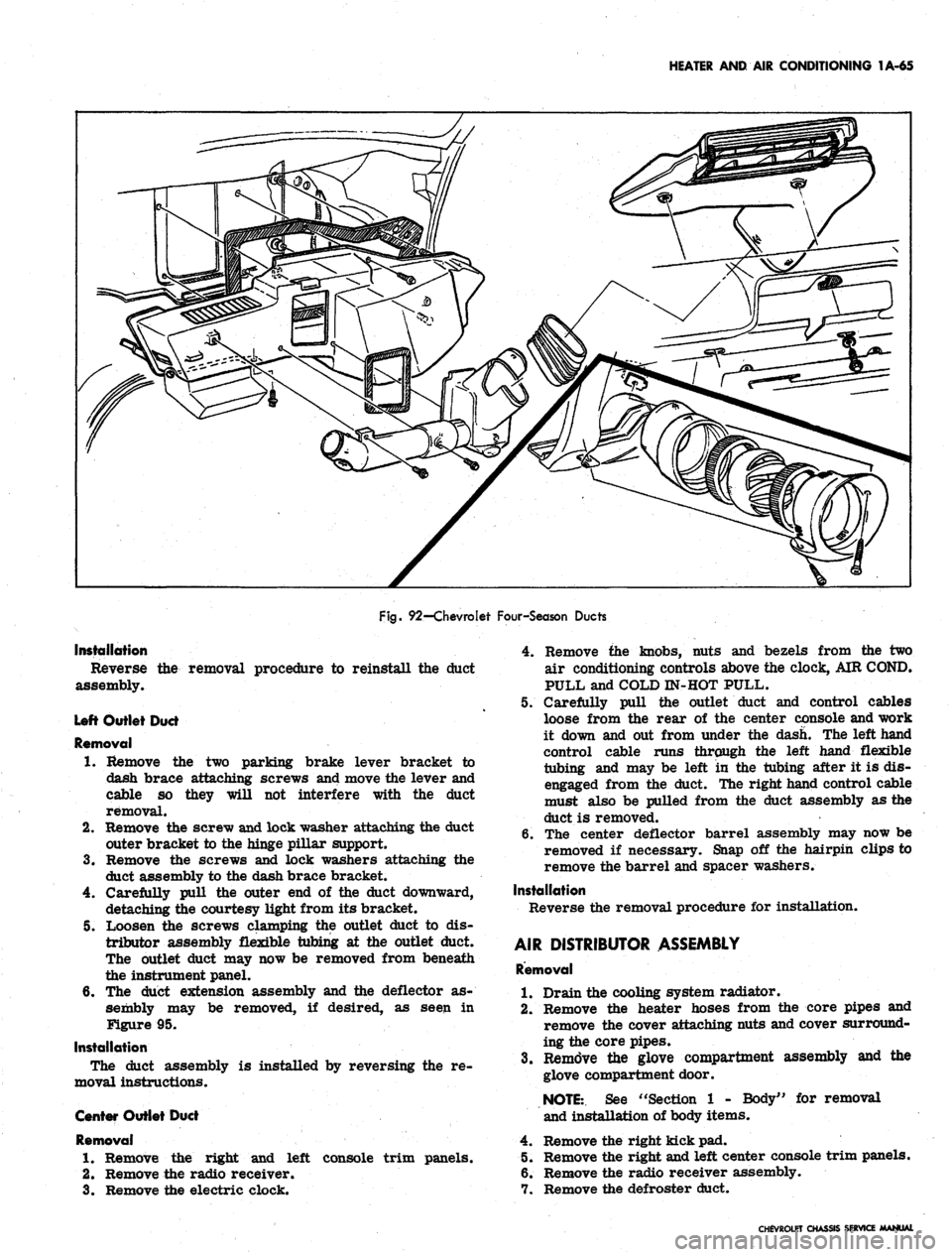
Figures 92 through .95 illustrate the air distributor and
outlet ducts as used in the Chevrolet, Chevelle, Camaro,
and Corvette.
Corvette
Right Outlet Duct
Removal
1.
Remove the clamp screw at the inner end of the
outlet duct and loosen the clamp.
2.
Remove the screw and lock washer attaching the
duct outer mounting tab to the body hinge pillar
brace.
3.
Pull the duct and clamp down and away from the
distributor assembly. Disconnect the courtesy light.
4.
The duct extension assembly may now be removed
if desired as well as the deflector assembly. See
Figure 95.
AIR COND.
PULL
AIR PULL- DEFROSTER
FAN PULL HOT PULL
Fig.
91—Corvette Four-Season Controls
CHEVROLET CHASSIS SERVICE MANUAL
Page 88 of 659
HEATER AND AIR CONDITIONING 1A-65
Fig.
92—Chevrolet Four-Season Ducts
Installation
Reverse
assembly.
the removal procedure to reinstall the duct
Left Outlet Duct
Removal
1.
Remove the two parking brake lever bracket to
dash brace attaching screws and move the lever and
cable so they will not interfere with the duct
removal.
2.
Remove the screw and lock washer attaching the duct
outer bracket to the hinge pillar support.
3.
Remove the screws and lock washers attaching the
duct assembly to the dash brace bracket.
4.
Carefully pull the outer end of the duct downward,
detaching the courtesy light from its bracket.
5. Loosen the screws clamping the outlet duct to dis-
tributor assembly flexible tubing at the outlet duct.
The outlet duct may now be removed from beneath
the instrument panel.
6. The duct extension assembly and the deflector as-
sembly may be removed, if desired, as seen in
Figure 95.
Installation
The duct assembly is installed by reversing the re-
moval instructions.
Center Outlet Duct
Removal
1.
Remove the right and left console trim panels.
2.
Remove the radio receiver.
3.
Remove the electric clock.
4.
Remove the knobs, nuts and bezels from the two
air conditioning controls above the clock, AIR COND.
PULL and COLD IN-HOT PULL.
5. Carefully pull the outlet duct and control cables
loose from the rear of the center console and work
it down and out from under the dash. The left hand
control cable runs through the left hand flexible
tubing and may be left in the tubing after it is dis-
engaged from the duct. The right hand control cable
must also be pulled from the duct assembly as the
duct is removed.
6. The center deflector barrel assembly may now be
removed if necessary. Snap off the hairpin clips to
remove the barrel and spacer washers.
Installation
Reverse the removal procedure for installation.
AIR DISTRIBUTOR ASSEMBLY
Removal
1.
Drain the cooling system radiator.
2.
Remove the heater hoses from the core pipes and
remove the cover attaching nuts and cover surround-
ing the core pipes.
3.
Remove the glove compartment assembly and the
glove compartment door.
NOTE:.
See "Section 1 - Body" for removal
and installation of body items.
4.
Remove the right kick pad.
5. Remove the right and left center console trim panels.
6. Remove the radio receiver assembly.
7. Remove the defroster duct.
CHEVROLET CHASSIS SERVICE MANUAL
Page 89 of 659
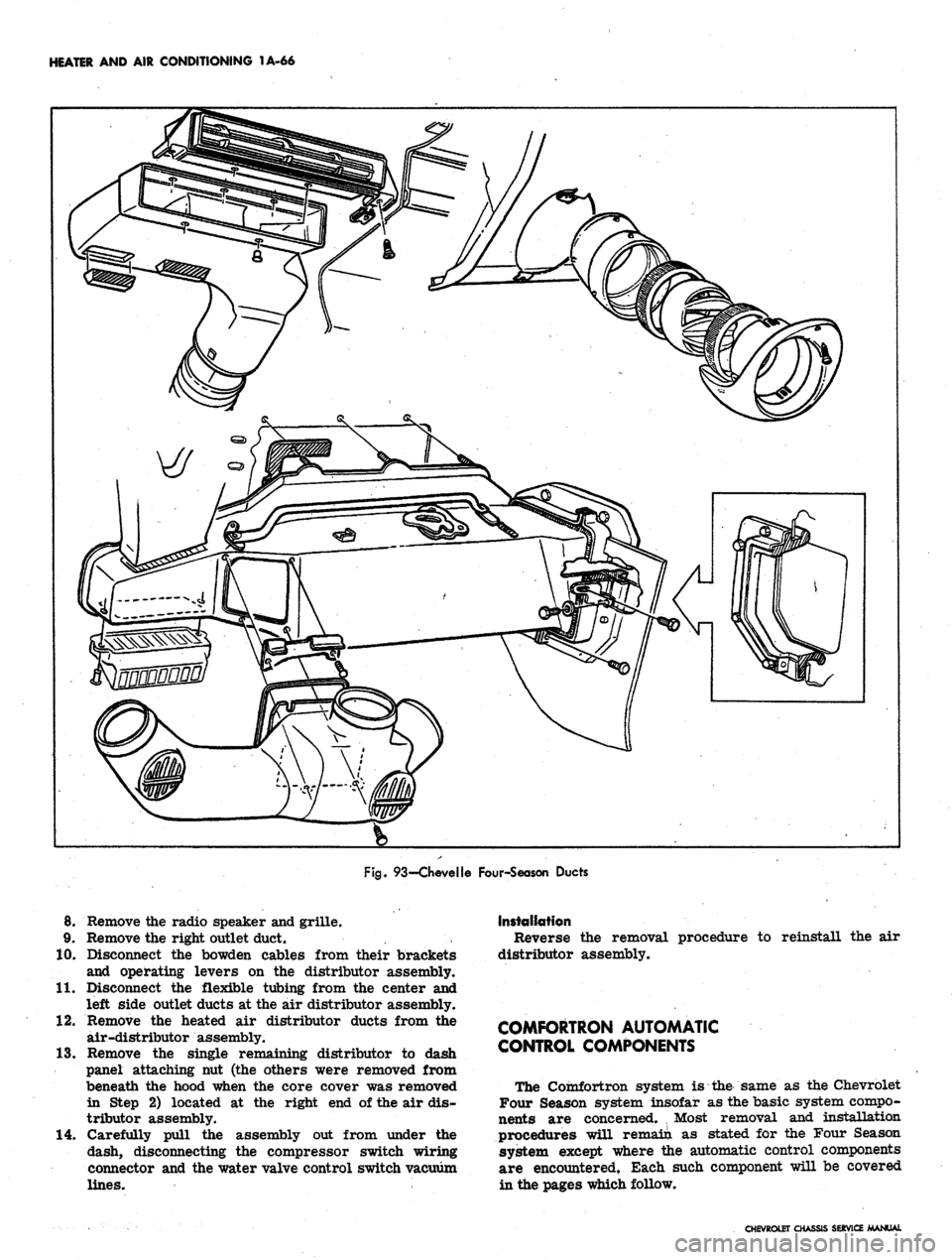
HEATER AND AIR CONDITIONING 1A-66
Fig.
93—Chevelle Four-Season Ducts
8. Remove the radio speaker and grille.
9. Remove the right outlet duct.
10.
Disconnect the bowden cables from their brackets
and operating levers on the distributor assembly.
11.
Disconnect the flexible tubing from the center and
left side outlet ducts at the air distributor assembly.
12.
Remove the heated air distributor ducts from the
air-distributor assembly.
13.
Remove the single remaining distributor to dash
panel attaching nut (the others were removed from
beneath the hood when the core cover was removed
in Step 2) located at the right end of the air dis-
tributor assembly.
14.
Carefully pull the assembly out from under the
dash, disconnecting the compressor switch wiring
connector and the water valve control switch vacuum
lines.
Installation
Reverse the removal procedure to reinstall the air
distributor assembly.
COMFORTRON AUTOMATIC
CONTROL COMPONENTS
The Comfortron system is the same as the Chevrolet
Four Season system insofar as the basic system compo-
nents are concerned. , Most removal and installation
procedures wUl remain as stated for the Four Season
system except where the automatic control components
are encountered. Each such component will be covered
in the pages which follow.
CHEVROLET CHASSIS SERVICE MANUAL
Page 90 of 659
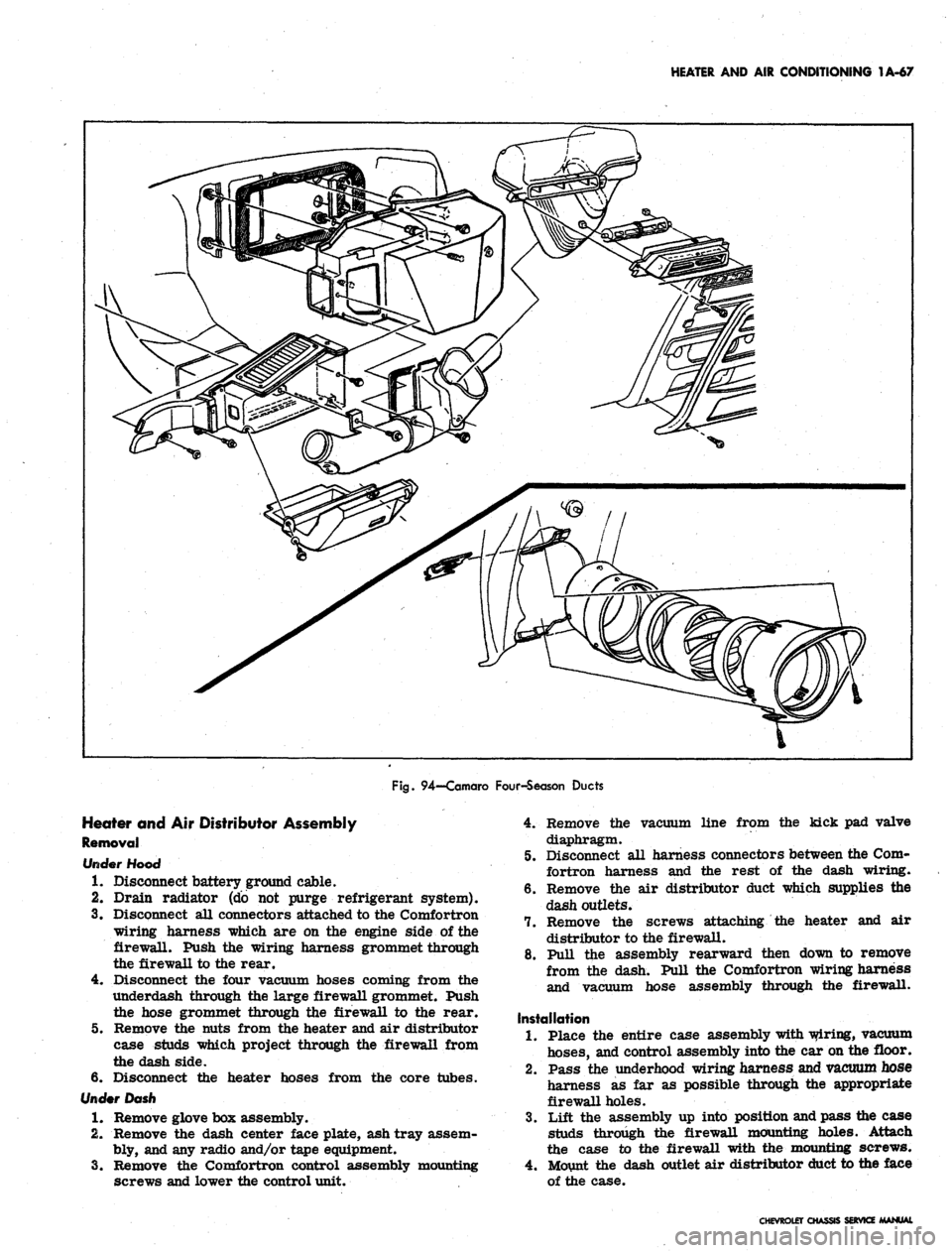
HEATER AND AIR CONDITIONING 1A-67
Fig.
94—Camaro Four-Season Ducts
Heater and Air Distributor Assembly
Removal
rfooo
1.
Disconnect battery ground cable.
2.
Drain radiator (do not purge refrigerant system).
3.
Disconnect all connectors attached to the Comfortron
wiring harness which are on the engine side of the
firewall. Push the wiring harness grommet through
the firewall to the rear.
4.
Disconnect the four vacuum hoses coming from the
underdash through the large firewall grommet. Push
the hose grommet through the firewall to the rear.
5.
Remove the nuts from the heater and air distributor
case studs which project through the firewall from
the dash side.
6. Disconnect the heater hoses from the core tubes.
Under Dash
1.
Remove glove box assembly.
2.
Remove the dash center face plate, ash tray assem-
bly, and any radio and/or tape equipment.
3.
Remove the Comfortron control assembly mounting
screws and lower the control unit.
4.
Remove the vacuum line from the kick pad valve
diaphragm.
5.
Disconnect all harness connectors between the Com-
fortron harness and the rest of the dash wiring.
6. Remove the air distributor duct which supplies the
dash outlets.
7.
Remove the screws attaching the heater and air
distributor to the firewall.
8. Pull the assembly rearward then down to remove
from the dash. Pull the Comfortron wiring harness
and vacuum hose assembly through the firewall.
Installation
1.
Place the entire case assembly with wiring, vacuum
hoses,
and control assembly into the car on the floor.
2.
Pass the underhood wiring harness and vacuum hose
harness as far as possible through the appropriate
firewall holes.
3.
Lift the assembly up into position and pass the case
studs through the firewall mounting holes. Attach
the case to the firewall with the mounting screws.
4.
Mount the dash outlet air distributor duct to the face
of the case.
CHEVROLET CHASSIS SERVICE MANUAL