CHEVROLET CAMARO 1967 1.G Chassis Workshop Manual
Manufacturer: CHEVROLET, Model Year: 1967, Model line: CAMARO, Model: CHEVROLET CAMARO 1967 1.GPages: 659, PDF Size: 114.24 MB
Page 111 of 659
CORVETTE BODY 1B-4
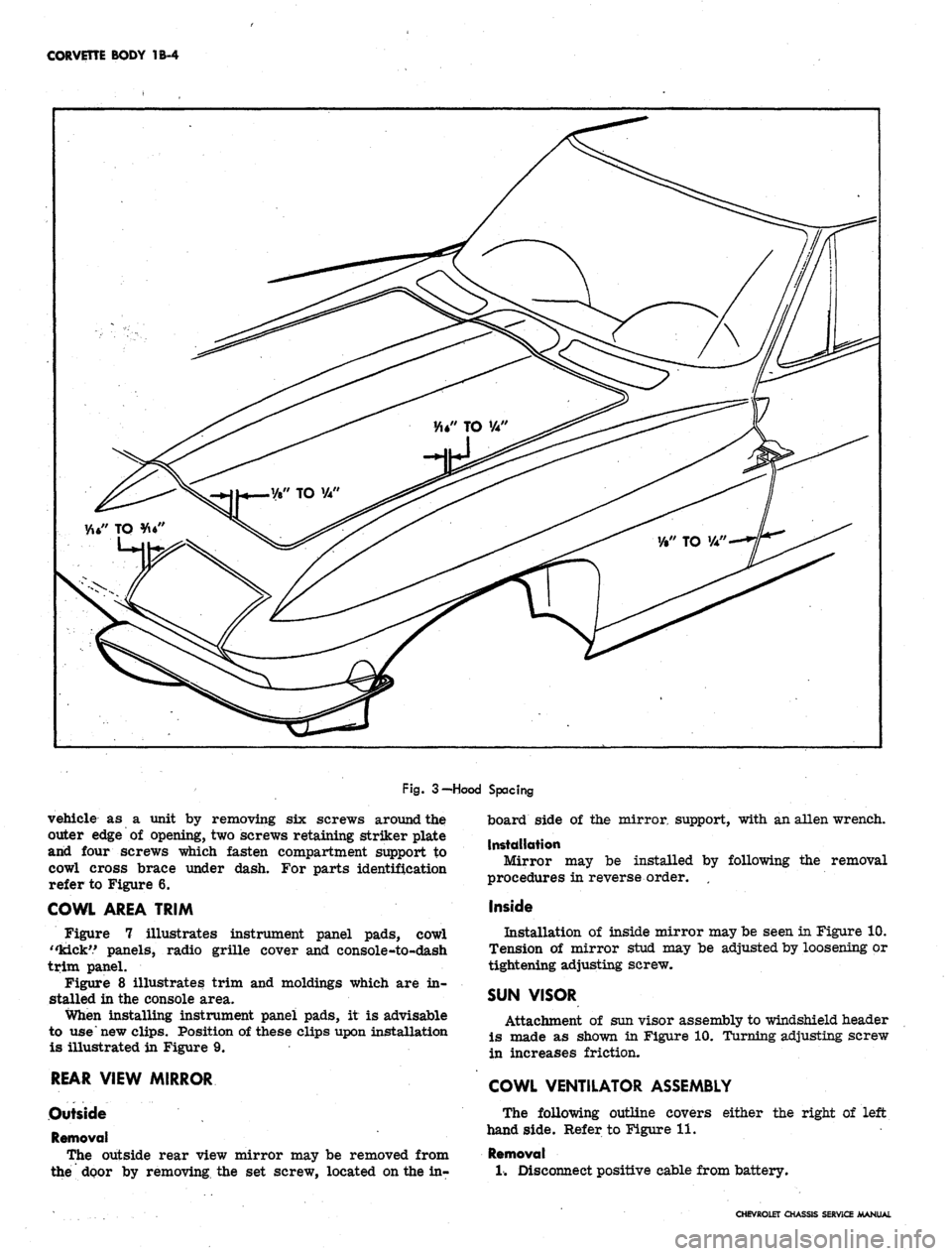
Fig.
3-Hood Spacing
vehicle as a unit by removing six screws around the
outer edge of opening, two screws retaining striker plate
and four screws which fasten compartment support to
cowl cross brace under dash. For parts identification
refer to Figure 6.
COWL AREA TRIM
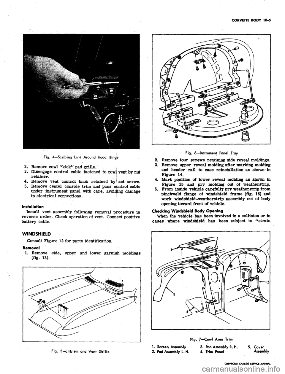
Figure 7 illustrates instrument panel pads, cowl
"kick'.' panels, radio grille cover and console-to-dash
trim panel.
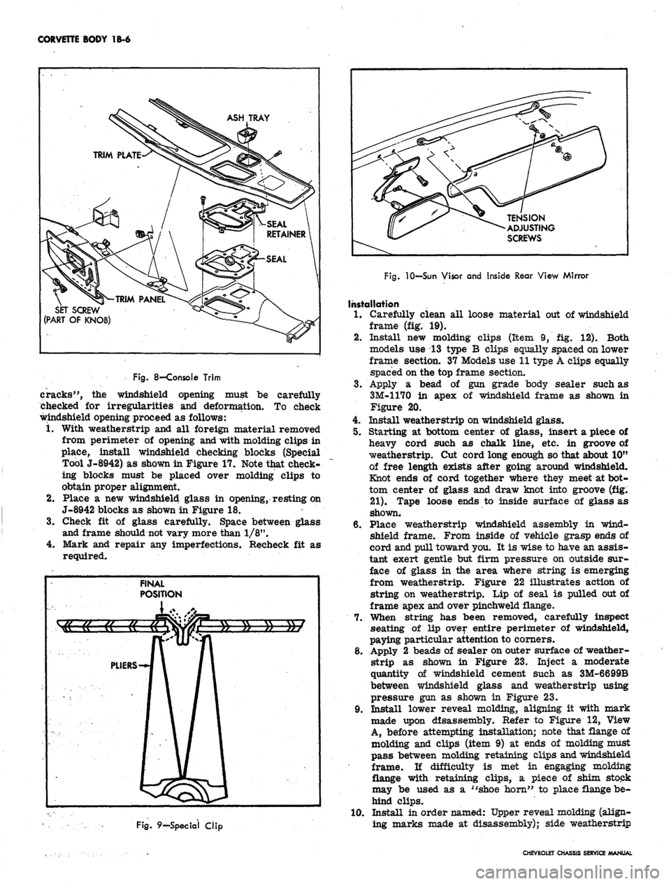
Figure 8 illustrates trim and moldings which are in-
stalled in the console area.
When installing instrument panel pads, it is advisable
to use new clips. Position of these clips upon installation
is illustrated in Figure 9.
REAR VIEW MIRROR
Outside
Removal
The outside rear view mirror may be removed from
the'
door by removing the set screw, located on the in-
board side of the mirror support, with an alien wrench.
Installation
Mirror may be installed by following the removal
procedures in reverse order. ,
Inside
Installation of inside mirror may be seen in Figure 10.
Tension of mirror stud may be adjusted by loosening or
tightening adjusting screw.
SUN VISOR
Attachment of sun visor assembly to windshield header
is made as shown in Figure 10. Turning adjusting screw
in increases friction.
COWL VENTILATOR ASSEMBLY
The following outline covers either the right of left
hand side. Refer to Figure 11.
Removal
1.
Disconnect positive cable from battery.
CHEVROLET CHASSIS SERVICE MANUAL
Page 112 of 659
CORVETTE BODY 1B-5
Fig.
4—Scribing
Line
Around
Hood
Hingje
2.
Remove cowl "kick" pad grille. |
3.
Disengage control cable fastened to cowl vent by nut
retainer. !
4.
Remove vent control knob retained by
|
set screw.
5. Remove center console trim and pass control cable
under instrument panel with care, avoiding damage
to electrical connections. j
Installation
Install vent assembly following removal procedure in
reverse order. Check operation of vent. Connect positive
battery cable.
Fig.
6—Instrument
Panel Tray
2.
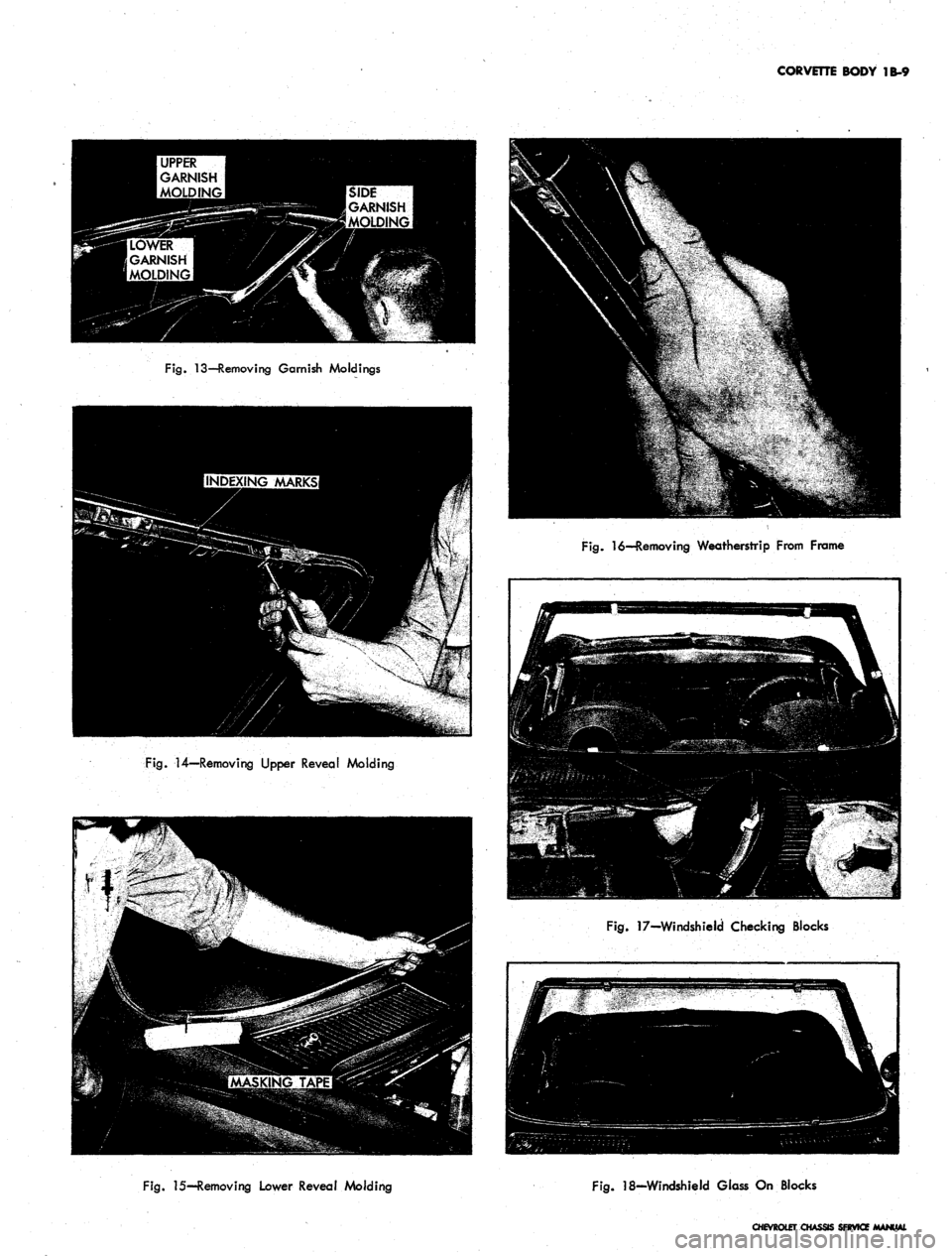
Remove four screws retaining side reveal moldings.
3.
Remove upper reveal molding after marking molding
and header rail to ease reinstallation as shown in
Figure 14.
4.
Mark position of lower reveal molding as shown in
Figure 15 and pry molding out of weatherstrip.
5. From inside vehicle carefully pry weatherstrip from
pinchweld flange of windshield frame (fig. 16) and
work windshield-weatherstrip assembly out of body
opening toward front of vehicle.
Checking Windshield Body Opening
When the vehicle has been involved in a collision or in
cases where windshield has been subject to "strain
WINDSHIELD
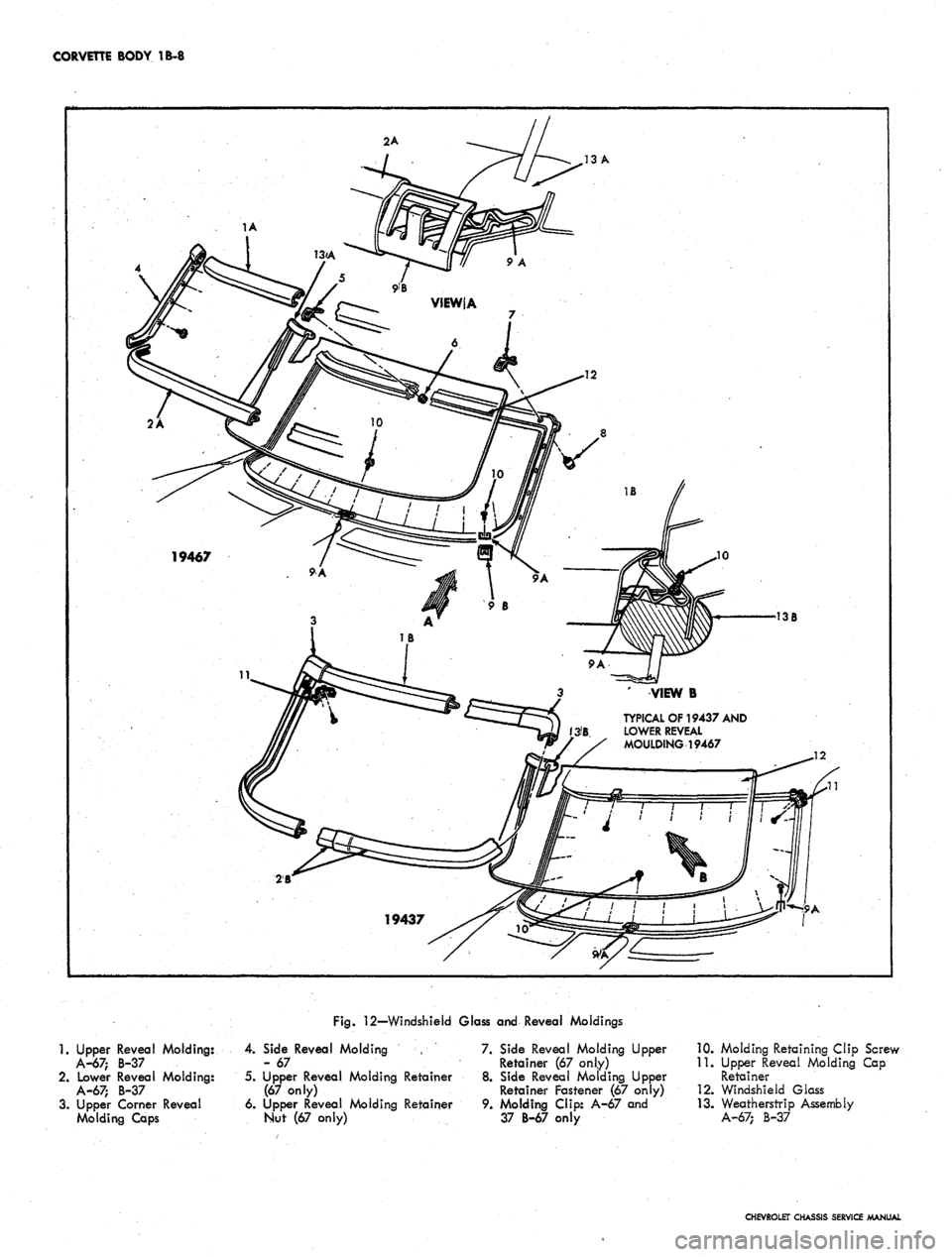
Consult Figure 12 for parts identification.
Removal
1.
Remove side, upper and lower garnish moldings
(fig. 13).
Fig.
5—Emblem dnd
Vent Grille
1.
Screen
Assembly
2.
Pad
Assembly
L H.
Fig.
7-Cowl
Area Trim
3.
Pad
Assembly
R. H. 5.
Cover
4.
Trim Panel
Assembly
CHEVROLET CHASSIS SERVICE MANUAL
Page 113 of 659
CORVETTE BODY
1B-6
ASH TRAY
SET SCREW
(PART
OF
KNOB)
TENSION
ADJUSTING
SCREWS
Fig.
8—Console Trim
cracks",
the
windshield opening must
be
carefully
checked
for
irregularities
and
deformation.
To
check
windshield opening proceed
as
follows:
1.
With weatherstrip
and all
foreign material removed
from perimeter
of
opening and with molding clips
in
place, install windshield checking blocks (Special
Tool J-8942)
as
shown in Figure 17. Note that check-
ing blocks must
be
placed over molding clips
to
obtain proper alignment.
2.
Place
a new
windshield glass
in
opening, resting on
J-8942 blocks
as
shown in Figure
18.
3.
Check
fit of
glass carefully. Space between glass
and frame should not vary more than 1/8".
4.
Mark
and
repair
any
imperfections. Recheck
fit as
required.
Fig.
9—Special Clip
Fig.
10—Sun Visor and Inside Rear View Mirror
Installation
1.
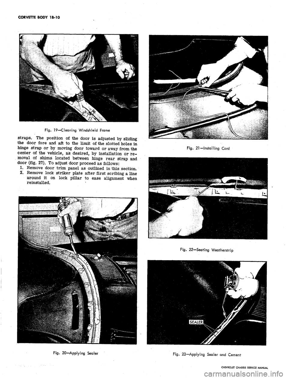
Carefully clean
all
loose material
out of
windshield
frame
(fig. 19).
2.
Install
new
molding clips (Item
9, fig. 12).
Both
models
use 13
type
B
clips equally spaced on lower
frame section.
37
Models use 11 type A clips equally
spaced on the top frame section.
3.
Apply
a
bead
of gun
grade body sealer such
as
3M-1170
in
apex
of
windshield frame
as
shown
in
Figure
20.
4.
Install weatherstrip on windshield glass.
5. Starting
at
bottom center
of
glass, insert
a
piece
of
heavy cord such
as
chalk line,
etc. in
groove
of
weatherstrip.
Cut
cord long enough so that about 10"
of free length exists after going around windshield.
Knot ends
of
cord together where they meet at bot-
tom center
of
glass
and
draw knot into groove
(fig.
21).
Tape loose ends
to
inside surface
of
glass
as
shown.
6. Place weatherstrip windshield assembly
in
wind-
shield frame. From inside
of
vehicle grasp ends
of
cord and pull toward you.
It is
wise to have an assis-
tant exert gentle
but
firm pressure
on
outside sur-
face
of
glass
in the
area where string
is
emerging
from weatherstrip. Figure
22
illustrates action
of
string
on
weatherstrip.
Lip of
seal
is
pulled out of
frame apex and over pinchweld flange.
7. When string
has
been removed, carefully inspect
seating
of lip
over entire perimeter
of
windshield,
paying particular attention to corners.
8. Apply
2
beads
of
sealer on outer surface
of
weather-
strip
as
shown
in
Figure
23.
Inject
a
moderate
quantity
of
windshield cement such
as
3M-6699B
between windshield glass
and
weatherstrip using
pressure gun
as
shown
in
Figure
23.
9. Install lower reveal molding, aligning
it
with mark
made upon disassembly. Refer
to
Figure
12,
View
A, before attempting installation; note that flange
of
molding
and
clips (item
9) at
ends
of
molding must
pass between molding retaining clips and windshield
frame.
li
difficulty
is met in
engaging molding
flange with retaining clips,
a
piece
of
shim stock
may
be
used
as a
"shoe horn"
to
place flange be-
hind clips.
10.
Install
in
order named: Upper reveal molding (align-
ing marks made
at
disassembly); side weatherstrip
CHEVROLET CHASSIS SERVICE MANUAL
Page 114 of 659

CORVETTE BODY
1B-7
HEAT
CONTROL
€P-
CABLE
VIEW A
HOOD RELEASE
Fig.
11—Cowl Ventilator
and
Controls
and reveal moldings; upper garnish molding; lower
garnish molding; side garnish molding; header latch
plates on 19467 Models and rear view mirror.
11.
Clean
up
excess sealer
and
cement with rag damp-
ened with oleum spirits, prep-sol
or
kerosene;
in-
stall wiper arm assemblies.
DOORS
ADJUSTMENTS
Door Lock Striker
Door lock strikers incorporate
an
inter-lock feature
consisting
of a
notch
in the
striker into which the lock
bolt housing extension engages. With
the
inter-lock
feature
it is
very important that
the
lock extension en-
gages properly
in the
striker notch
and
that, where
necessary,
the
correct striker emergency spacers
are
used to obtain proper engagement.
1.
To
adjust striker
up,
down,
in, or
out loosen striker
plate screws and shift striker and adjusting plates
as
required, then tighten screws.
2.
To determine
if
door lock striker emergency spacers
are required, apply modeling clay
or
body caulking
compound
in the
door lock striker notch where
the
lock extension engages,
and
then close
the
door
to
form
a
measurable impression in the clay
or
caulk-
ing compound,
as
shown
in
Figure
24.
Remove
all
clay
or
compound when adjustment
is
completed.
When dimension
"A"
from inside face
of
striker teeth
to center
of
lock extension
is
less than 3/16", install
emergency spacers
and
proper length striker attaching
screws.
NOTE:
Dimension
"B"
from center
of
lock
extension
to
inside face
of
striker notch should
.
never be less than 1/8".
If check indicates need
for
emergency spacers,
pro-
ceed
as
follows:
1.
With pencil, scribe position
of
striker on body pillar.
2.
Remove three door lock striker attaching screws and
remove striker
and
adjusting plates from pillar.
3.
To
install, place striker, shims and adjusting plates
within scribe marks
on
pillar
and
tighten screws.
IMPORTANT: Whenever
a
door
has
been
re-
moved
and
installed,
or
realigned,
the
door
SHOULD NOT be closed completely until
a
visual
check
is
made to determine
if
the lock extension/
will engage
in the
striker notch. Where
re-
quired, door lock striker emergency spacers
should
be
installed
so
that door
can be
closed
and
an
accurate check made to determine emer-
gency spacer requirements.
Door Window and Vent Adjustment
To move
the top of the
window
in or
out, the bottom
ends
of
both
run
channels
are
adjustable.
The
rear
channel
is
adjusted
by
loosening
the
lower
of
the two
screws
on the
rear face
of
door, "C" Figure 25, and
moving channel
as
necessary.
The
front channel
is ad-
justed
by
removing
the
trim pad and moving the Channel
in
or out by a
stud
and nut
adjustment, "B" Figure 25.
The
top end of the
rear channel
is
not adjustable in
or
out.
On 19467 models
an
adjustment
may be
made
to the
closed-door relationship
of the
vent assembly
to the
windshield frame. This adjustment
is
controlled
by the
stud-nut assembly "B" Figure
25.
The closed position
of the
window
is
controlled
by
bumper assemblies located
at
each end
of
window frame
as shown
in
Figure
26.
^
Access
to
bumper retaining
screw
may be
gained through holes
"D" and
"E"
in
Figure
25.
Door Hinges
The position
of the
door assembly in the body opening
is adjusted
by the
striker plate position covered
pre-
viously
and the
position
of the
door
on
the hinge rear
CHEVROLET
a
SERVICE
Page 115 of 659
CORVETTE
BODY 1B-8
2A
13
A
TYPICAL
OF 19437
AND
/3'B
LOWER
REVEAL
MOULDING
19467
13B
2B
Fig.
12—Windshield Glass and Reveal Moldings
1.
Upper Reveal Molding:
A-67;
B-37
2.
Lower Reveal Molding:
A-67;
B-37
3.
Upper Corner Reveal
Molding
Caps
4.
Side Reveal Molding
- 67
5.
Upper Reveal Molding Retainer
(67 only)
6. Upper Reveal Molding Retainer
Nut (67 only)
7.
Side Reveal Molding Upper
Retainer (67 only)
8. Side Reveal Molding Upper
Retainer Fastener (67 only)
9. Molding Clip: A-67 and
37 B-67 only
10.
Molding Retaining Clip Screw
11.
Upper Reveal Molding Cap
Retainer
12.
Windshield Glass
13.
Weatherstrip Assembly
A-67;
B-37
CHEVROLET CHASSIS SERVICE MANUAL
Page 116 of 659
CORVETTE BODY 1B-9
Fig.
13—Removing Garnish Moldings
Fig.
14—Removing Upper Reveal Molding
Fig.
16—Removing Weatherstrip From Frame
Fig.
17-Windshield Checking Blocks
Fig.
15—Removing Lower Reveal Molding
Fig.
18-Windshield Glass On Blocks
CHEVROLET CHASSIS SERVICE
Page 117 of 659
CORVETTE BODY IB-10
Fig.
19—Cleaning Windshield Frame
straps.
The position of the door is adjusted by sliding
the door fore and aft to the limit of the slotted holes in
hinge strap or by moving door toward or away from the
center of the vehicle, as desired, by installation or re-
moval of shims located between hinge rear strap and
door (fig. 27). To adjust door proceed as follows:
1.
Remove door trim panel as outlined in this section.
2.
Remove lock striker plate after first scribing a line
around it on lock pillar to ease alignment when
reinstalled. '
Fig. 21-Installing Cord
Fig. 22—Seating Weatherstrip
Fig. 20—Applying Sealer
Fig. 23—Applying Sealer and Cement
CHEVROLET CHASSIS SERVICE MANUAL
Page 118 of 659

CORVETTE BODY 1B-11
CLAYOfc
CAULKING
COMPOUND
Fig. 26-Window Rear Stop - Typical
Fig. 24—Checking Adjustment of Striker
3.
Adjust door as required. Location of hinge retaining
bolts may be seen in Figure 25 at "A". Do not allow
doors to hang on one hinge without support.
4.
Install trim pad and lubricate door "hold opens" and
hinges with Lubriplate or its equivalent.
NOTE:
After performing any door adjustment,
the window and door post should be checked for
alignment and adjusted as necessary. In addi-
tion,
never slam the door after adjustment with-
out first checking the door lock and striker plate
engagement. An adjustment may be necessary.
TRIM PANEL, AND INSIDE HANDLES
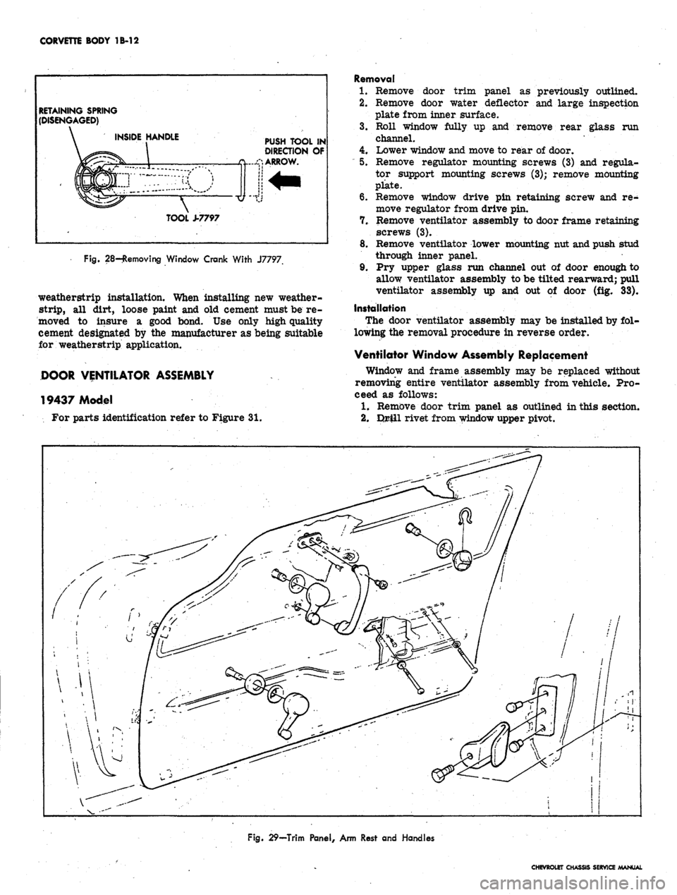
Figure 29 is an exploded view of integral arm rest,
inside handles, and trim panel fastenings.
Removal of trim panel may be accomplished as
follows:
1.
Remove two screws under arm rest.
2.
Using Tool J-7797, remove clips retaining window
crank and lock remote control as shown in Figure 28.
3.
Remove knob from door lock control by turning
counter-clockwise.
4.
Remove 2 screws retaining inside pull handle.
5. Remove sheet metal screws and special washers
retaining trim panel to door assembly.
6. Pull trim panel out. at bottom, tap bottom edge of
trim panel with hand to disengage from top of door.
Remove trim panel from vehicle.
WEATHERSTRIP
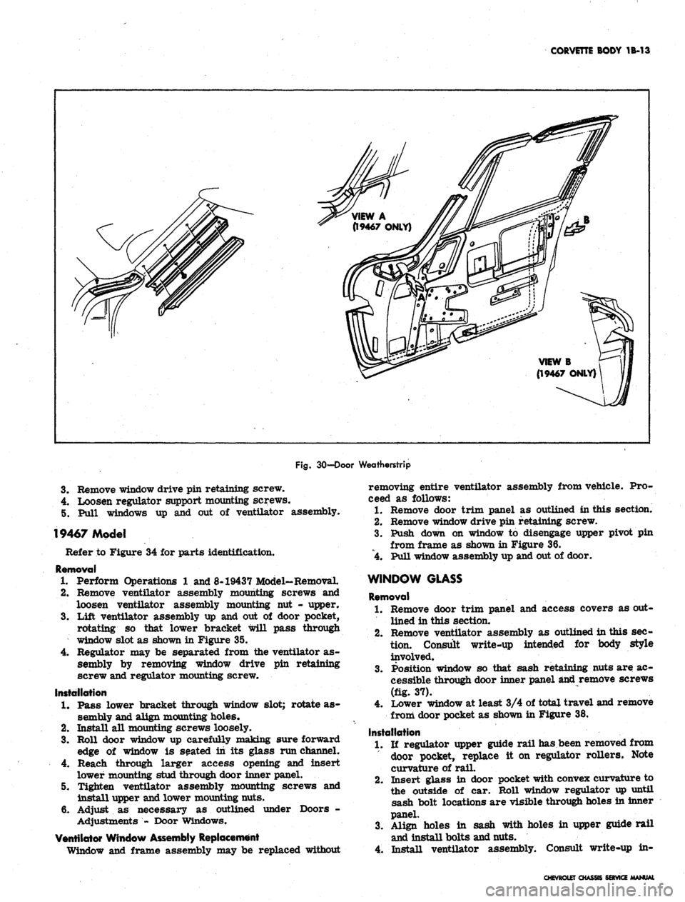
Figure
30
illustrates both 19437 and 19467 model door
COWL
Fig.
25-Door Adjustment Points
Fig.
27-Door Hinge
CHEVROLET CHASSIS SERVICE MANUAL
Page 119 of 659
CORVETTE BODY 1B-12
RETAINING SPRING
(DISENGAGED)
INSIDE HANDLE
PUSH TOOL IN
DIRECTION OF
ARROW.
TOOL ±7797
Fig. 28-Removing Window Crank With J7797
weatherstrip installation. When installing new weather-
strip,
all dirt, loose paint and old cement must be re-
moved to insure a good bond. Use only high quality
cement designated by the manufacturer as being suitable
for weatherstrip application.
DOOR VENTILATOR ASSEMBLY
19437 Model
For parts identification refer to Figure 31.
Removal
1.
Remove door trim panel as previously outlined.
2.
Remove door water deflector and large inspection
plate from inner surface.
3.
Roll window fully up and remove rear glass run
channel. •
4.
Lower window and move to rear of door.
"
5. Remove regulator mounting screws (3) and regula-
tor support mounting screws (3); remove mounting
plate.
6. Remove window drive pin retaining screw and re-
move regulator from drive pin.
7. Remove ventilator assembly to door frame retaining
screws (3).
8. Remove ventilator lower mounting nut and push stud
through inner panel.
9. Pry upper glass run channel out of door enough to
allow ventilator assembly to be tilted rearward; pull
ventilator assembly up and out of door (fig. 33).
Installation
The door ventilator assembly may be installed by fol-
lowing the removal procedure in reverse order.
Ventilator Window Assembly Replacement
Window and frame assembly may be replaced without
removing entire ventilator assembly from vehicle. Pro-
ceed as follows:
1.
Remove door trim panel as outlined in this section.
2.
Drill rivet from window upper pivot.
Fig. 29—Trim Panel, Arm Rest and Handles
CHEVROLET CHASSIS SERVICE MANUAL
Page 120 of 659
CORVETTE BODY 1B-13
Fig.
30-Door Weatherstrip
3.
Remove window drive pin retaining screw.
4.
Loosen regulator support mounting screws.
5. Pull windows up and out of ventilator assembly.
19467 Model
Refer to Figure 34 for parts identification.
Removal
1.
Perform Operations 1 and 8-19437 Model-Removal.
2.
Remove ventilator assembly mounting screws and
loosen ventilator assembly mounting nut - upper.
3.
Lift ventilator assembly up and out of door pocket,
rotating so that lower bracket will pass through
window slot as shown in Figure 35.
4.
Regulator may be separated from the ventilator as-
sembly by removing window drive pin retaining
screw and regulator mounting screw.
Installation
1.
Pass lower bracket through window slot; rotate as-
sembly and align mounting holes*
2.
Install all mounting screws loosely.
3.
Roll door window up carefully making sure forward
edge of window is seated in its glass run channel.
4.
Reach through larger access opening and insert
lower mounting stud through door inner panel.
5. Tighten ventilator assembly mounting screws and
install upper and lower mounting nuts.
6. Adjust as necessary as outlined under Doors -
Adjustments - Door Windows.
Ventilator Window Assembly Replacement
Window and frame assembly may be replaced without
removing entire ventilator assembly from vehicle. Pro-
ceed as follows:
1.
Remove door trim panel as outlined in this section.
2.
Remove window drive pin retaining screw.
3.
Push down on window to disengage upper pivot pin
from frame as shown in Figure 36.
4.
Pull window assembly up and out of door.
WINDOW GLASS
Removal
1.
Remove door trim panel and access covers as out-
lined in this section.
2.
Remove ventilator assembly as outlined in this sec+
tion.
Consult write-up intended for body style
involved.
Position window so that sash retaining nuts are ac-
cessible through door inner panel and remove screws
(fig. 37).
Lower window at least 3/4 of total travel and remove
3.
4.
from door pocket as shown in Figure 38.
Installation
1.
If regulator upper guide rail has been removed from
door pocket, replace it on regulator rollers. Note
curvature of rail.
2.
Insert glass in door pocket with convex curvature to
the outside of car. Roll window regulator up until
sash bolt locations are visible through holes in inner
panel.
3.
Align holes in sash with holes in upper guide rail
and install bolts and nuts.
4.
Install ventilator assembly. Consult write-up in-
CHEVROLETCH>
SERVICE