CHEVROLET CAMARO 1967 1.G Chassis Owners Manual
Manufacturer: CHEVROLET, Model Year: 1967, Model line: CAMARO, Model: CHEVROLET CAMARO 1967 1.GPages: 659, PDF Size: 114.24 MB
Page 91 of 659
HEATER AND AIR CONDITIONING 1A-68
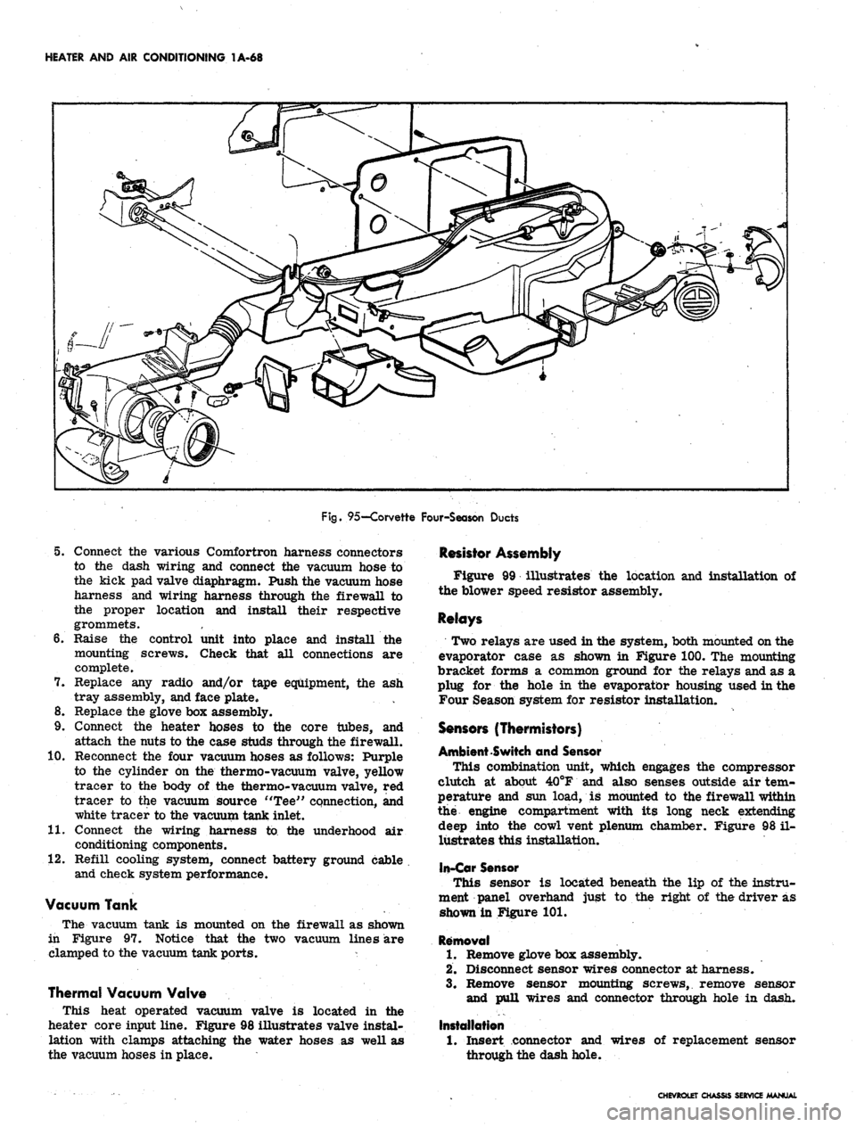
Fig.
95—Corvette Four-Season Ducts
5. Connect the various Comfortron harness connectors
to the dash wiring and connect the vacuum hose to
the kick pad valve diaphragm. Push the vacuum hose
harness and wiring harness through the firewall to
the proper location and install their respective
grommets.
6. Raise the control unit into place and install the
mounting screws. Check that all connections are
complete.
7. Replace any radio and/or tape equipment, the ash
tray assembly, and face plate.
8. Replace the glove box assembly.
9. Connect the heater hoses to the core tubes, and
attach the nuts to the case studs through the firewall.
10.
Reconnect the four vacuum hoses as follows: Purple
to the cylinder on the thermo-vacuum valve, yellow
tracer to the body of the thermo-vacuum valve, red
tracer to the vacuum source "Tee" connection, and
white tracer to the vacuum tank inlet.
11.
Connect the wiring harness to the underhood air
conditioning components.
12.
Refill cooling system, connect battery ground cable
and check system performance.
Vacuum Tank
The vacuum tank is mounted on the firewall as shown
in Figure 97. Notice that the two vacuum lines are
clamped to the vacuum tank ports. *
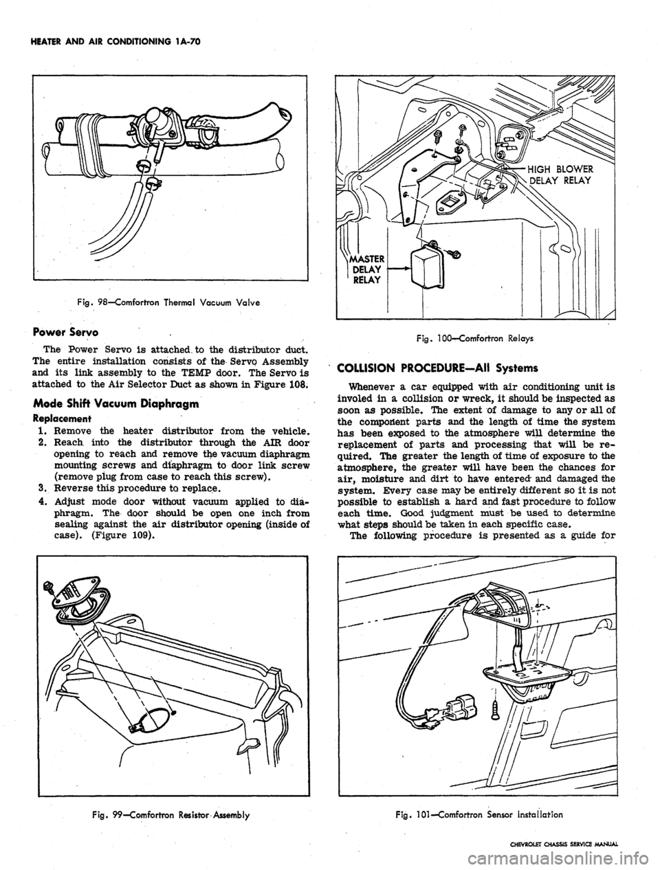
Thermal Vacuum Valve
This heat operated vacuum valve is located in the
heater core input line. Figure 98 illustrates valve instal-
lation with clamps attaching the water hoses as well as
the vacuum hoses in place.
Resistor Assembly
Figure 99 illustrates the location and installation of
the blower speed resistor assembly.
Relays
Two relays are used in the system, both mounted on the
evaporator case as shown in Figure 100. The mounting
bracket forms a common ground for the relays and as a
plug for the hole in the evaporator housing used in the
Four Season system for resistor installation.
Sensors (Thermistors)
Ambient Switch and Sensor
This combination unit, which engages the compressor
clutch at about 40°F and also senses outside air tem-
perature and sun load, is mounted to the firewall within
the engine compartment with its long neck extending
deep into the cowl vent plenum chamber. Figure 98 il-
lustrates this installation,
In-Car Sensor
This sensor is located beneath the lip of the instru-
ment panel overhand just to the right of the driver as
shown in Figure 101.
Removal
1.
Remove glove box assembly.
2.
Disconnect sensor wires connector at harness.
3.
Remove sensor mounting screws, remove sensor
and pull wires and connector through hole in dash.
Installation
1.
Insert connector and
through the dash hole.
wires of replacement sensor
CHEVROLET CHASSIS SERVICE MANUAL
Page 92 of 659
HEATER AND AIR CONDITIONING 1A-69
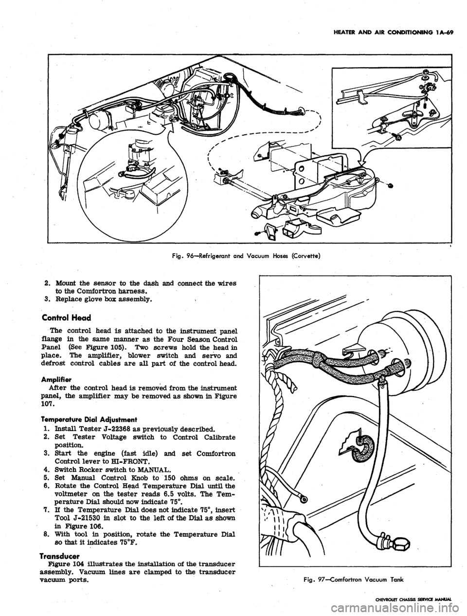
Fig.
96—Refrigerant and Vacuum Hoses (Corvette)
2.
Mount the sensor to the dash and connect the wires
to the Comfortron harness.
3.
Replace glove box assembly.
Control Head
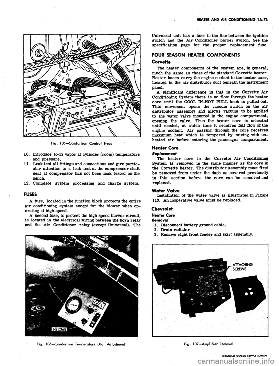
The control head is attached to the instrument panel
flange in the same manner as the Four Season Control
Panel (See Figure 105). Two screws hold the head in
place. The amplifier, blower switch and servo and
defrost control cables are all part of the control head.
Amplifier
After the control head is removed from the instrument
panel, the amplifier may be removed as shown in Figure
107.
Temperature Dial Adjustment
1.
Install Tester J-22368 as previously described.
2.
Set Tester Voltage switch to Control Calibrate
position.
3.
Start the engine (fast idle) and set Comfortron
Control lever to HI-FRONT.
4.
Switch Rocker switch to MANUAL.
5. Set Manual Control Knob to 150 ohms on scale.
6. Rotate the Control Head Temperature Dial until the
voltmeter on the tester reads 6.5 volts. The Tem-
perature Dial should now indicate 75°.
7. If the Temperature Dial does not indicate 75°, insert
Tool J-21530 in slot to the left of the Dial as shown
in Figure 106.
8. With tool in position, rotate the Temperature Dial
so that it indicates 75°F.
Transducer
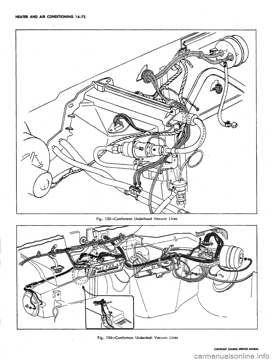
Figure 104 illustrates the installation of the transducer
assembly. Vacuum lines are clamped to the transducer
vacuum ports.
Fig.
97—Comfortron Vacuum Tank
CHEVROLET CHASSIS SERVICE JWANUAl
Page 93 of 659
HEATER AND AIR CONDITIONING 1A-70
Fig.
98—Comfortron Thermal Vacuum Valve
Power Servo .
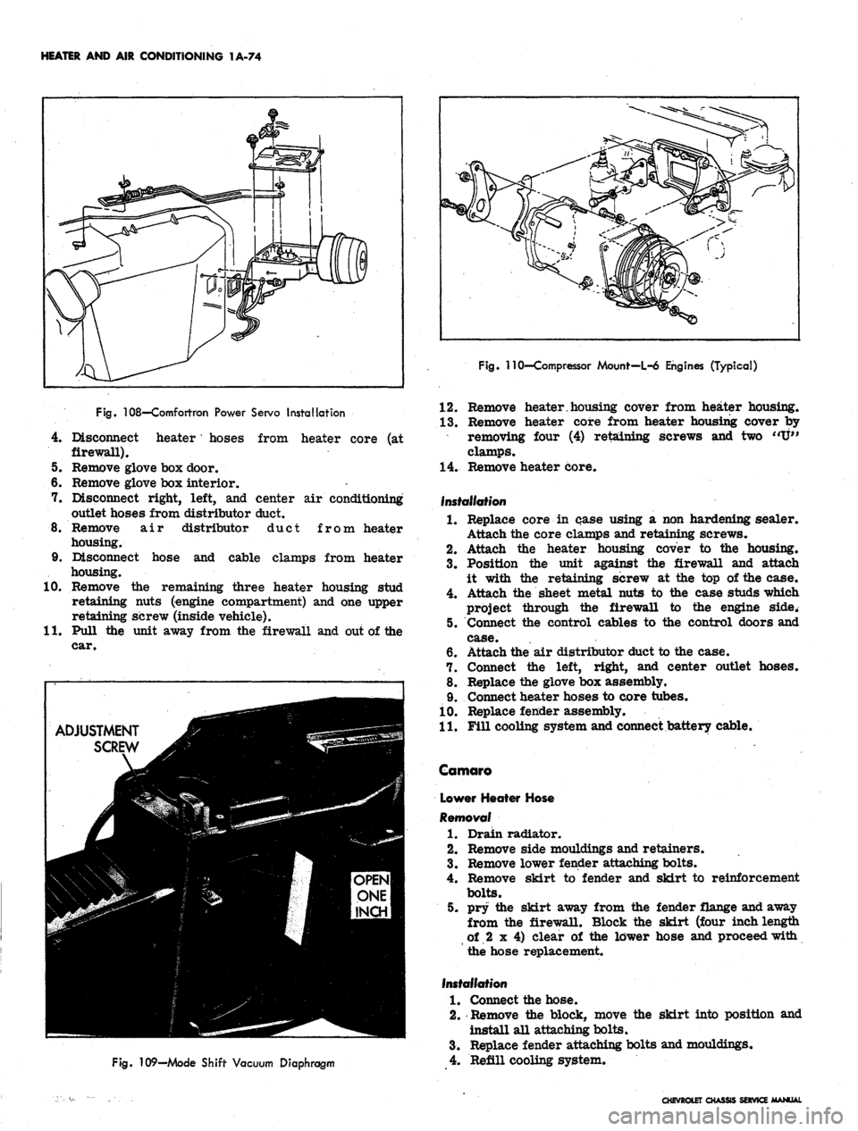
The Power Servo is attached, to the distributor duct.
The entire installation consists of the Servo Assembly
and its link assembly to the TEMP door. The Servo is
attached to the Air Selector Duct as shown in Figure 108.
Mode Shift Vacuum Diaphragm
Replacement
1.
Remove the heater distributor from the vehicle.
2.
Reach into the distributor through the AIR door
opening to reach and remove the vacuum diaphragm
mounting screws and diaphragm to door link screw
(remove piug from case to reach this screw).
3.
Reverse this procedure to replace.
4.
Adjust mode door without vacuum applied to dia-
phragm. The door should be open one inch from
sealing against the air distributor opening (inside of
case).
(Figure 109).
HIGH BLOWER
DELAY RELAY
.MASTER
DELAY
RELAY
Fig.
100—Comfortron Relays
COLLISION PROCEDURE-AII Systems
Whenever a car equipped with air conditioning unit is
involed in a collision or wreck, it should be inspected as
soon as possible. The extent of damage to any or all of
the component parts and the length of time the system
has been exposed to the atmosphere will determine the
replacement of parts and processing that will be re-
quired. The greater the length of time of exposure to the
atmosphere, the greater will have been the chances for
air, moisture and dirt to have entered and damaged the
system. Every case may be entirely different so it is not
possible to establish a hard and fast procedure to follow
each time. Good judgment must be used to determine
what steps should be taken in each specific case.
The following procedure is presented as a guide for
Fig.
99—Comfortron Resistor Assembly
Fig.
101—Comfortron Sensor Installation
CHEVROLET CHASSIS SERVICE MANUAL
Page 94 of 659
HEATER AND AIR CONDITIONING 1A-71
SUN-AMBIENT
SENSOR AND COMPRESSOR
CLUTCH SWITCH
HIGH BLOWER
DELAY RELAY
THERMAL
VACUUM
VALVE
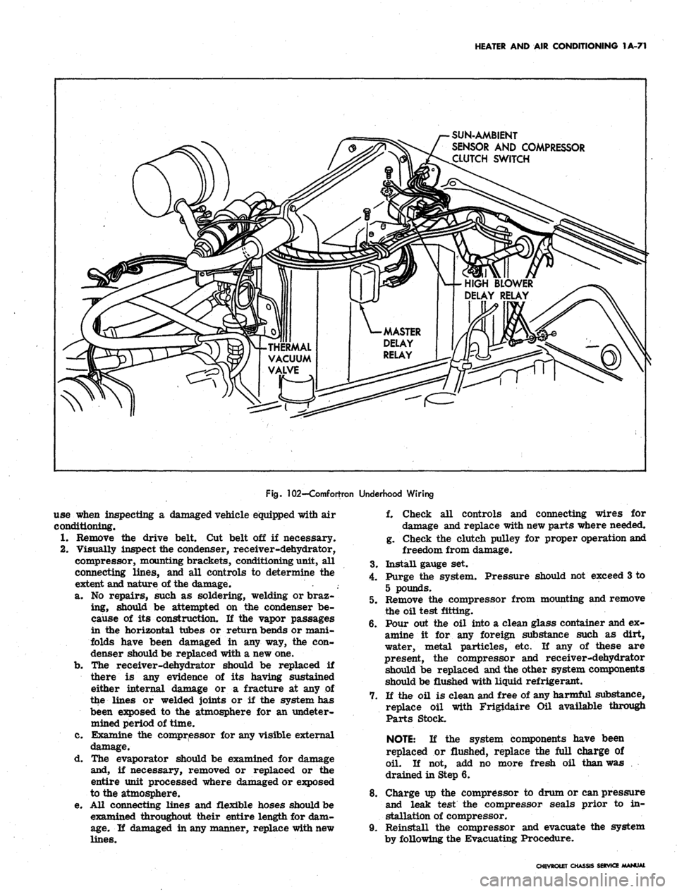
Fig.
102-Comfortron Underhood Wiring
use when inspecting a damaged vehicle equipped with air
conditioning.
1.
Remove the drive belt. Cut belt off if necessary.
2.
Visually inspect the condenser, receiver-dehydrator,
compressor, mounting brackets, conditioning unit, all
connecting lines, and all controls to determine the
extent and nature of the damage.
a. No repairs, such as soldering, welding or braz-
ing, should be attempted on the condenser be-
cause of its construction. If the vapor passages
in the horizontal tubes or return bends or mani-
folds have been damaged in any way, the con-
denser should be replaced with a new one.
b.
The receiver-dehydrator should be replaced if
there is any evidence of its having sustained
either internal damage or a fracture at any of
the lines or welded joints or if the system has
been exposed to the atmosphere for an undeter-
mined period of time.
c. Examine the compressor for any visible external
damage.
d. The evaporator should be examined for damage
and, if necessary, removed or replaced or the
entire unit processed where damaged or exposed
to the atmosphere.
e. All connecting lines and flexible hoses should be
examined throughout their entire length for dam-
age.
If damaged in any manner, replace with new
lines.
f. Check all controls and connecting wires for
damage and replace with new parts where needed.
g. Check the clutch pulley for proper operation and
freedom from damage.
3.
Install gauge set.
4.
Purge the system. Pressure should not exceed 3 to
5 pounds.
5. Remove the compressor from mounting and remove
the oil test fitting.
6. Pour out the oil into a clean glass container and ex-
amine it for any foreign substance such as dirt,
water, metal particles, etc. If any of these are
present, the compressor and receiver-dehydrator
should be replaced and the other system components
should be flushed with liquid refrigerant.
7. If the oil is clean and free of any harmful substance,
replace oil with Frigidaire Oil available through
Parts Stock.
NOTE:
If the system components have been
replaced or flushed, replace the full charge of
oil. If not, add no more fresh oil than was
drained in Step 6.
8. Charge up the compressor to drum or can pressure
and leak test the compressor seals prior to in-
stallation of compressor.
9. Reinstall the compressor and evacuate the system
by following the Evacuating Procedure.
CHEVROLET CHASSIS SERVICE MANUAL
Page 95 of 659
HEATER AND AIR CONDITIONING 1A-72
Fig.
103—Comforrron Underhood Vacuum Lines
Fig.
104—Comfortron Underdash Vacuum Lines
CHEVROLET CHASSIS SERVICE MANUAL
Page 96 of 659
HEATER AND AIR CONDITIONING 1A-73
Fig.
105—Comfortron Control Head
10.
Introduce R-12 vapor at cylinder (room) temperature
and pressure.
11.
Leak test all fittings and connections and give partic-
ular attention to a leak test at the compressor shaft
seal if compressor has not been leak tested on the
bench.
12.
Complete system processing and charge system.
FUSES
A fuse, located in the junction block protects the entire
air conditioning system except for the blower when op-
erating at high speed.
A second fuse, to protect the high speed blower circuit,
is located in the electrical wiring between the horn relay
and the Air Conditioner relay (except Universal). The
Universal unit has a fuse in the line between the ignition
switch and the Air Conditioner blower switch. See the
specification page for the proper replacement fuse.
FOUR SEASON HEATER COMPONENTS
Corvette
The heater components of the system are, in general,
much the same as those of the standard Corvette heater.
Heater hoses carry the engine coolant to the heater core,
located in the air distributor duct beneath the instrument
panel.
A significant difference is that in the Corvette Air
Conditioning System there is no flow through the heater
core until the COOL IN-HOT PULL knob is pulled out.
This movement opens the vacuum switch on the air
distributor assembly and allows vacuum to be applied
to the water valve mounted in the engine compartment,
opening the valve. Thus the heater core is unheated
until needed, at which time it receives full flow of the
engine coolant. Air passing through the core receives
maximum heat which is tempered by mixing with un-
heated air before entering the passenger compartment.
Heater Core
Replacement
The heater core in the Corvette Air Conditioning
System is removed in the same manner as the core in
the Corvette heater. The distributor assembly must first
be removed from under the dash as covered previously
in this section before the core can be removed and
replaced.
Water Valve
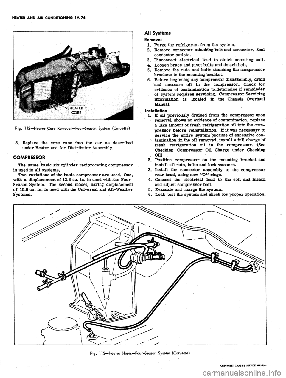
Installation of the water valve is illustrated in Figure
113.
An inoperative valve must be replaced.
Chevrolet
Heater Core
Removal
1.
Disconnect battery ground cable.
2.
Drain radiator
3.
Remove right front fender and skirt assembly.
Fig.
106—Comfortron Temperature Dial Adjustment
Fig.
107—Amplifier Removal
CHEVROLET CHASSIS SERVICE MANUAL
Page 97 of 659
HEATER AND AIR CONDITIONING 1A-74
Fig.
108—Comfortron Power Servo Installation
4.
Disconnect heater' hoses from heater core (at
firewall).
5. Remove glove box door.
6. Remove glove box interior.
7. Disconnect right, left, and center air conditioning
outlet hoses from distributor duct.
8. Remove air distributor duct from heater
housing.
9. Disconnect hose and cable clamps from heater
housing.
10.
Remove the remaining three heater housing stud
retaining nuts (engine compartment) and one upper
retaining screw (inside vehicle).
11.
Pull the unit away from the firewall and out of the
car.
ADJUSTMENT
SCREW
Fig.
109—Mode Shift Vacuum Diaphragm
Fig. 110'—Compressor Mount—L-6 Engines (Typical)
12.
Remove heater.housing cover from heater housing.
13.
Remove heater core from heater housing cover by
removing four (4) retaining screws and two "U"
clamps.
14.
Remove heater core.
Installation
1.
Replace core in case using a non hardening sealer.
Attach the core clamps and retaining screws.
2.
Attach the heater housing cover to the housing.
3.
Position the unit against the firewall and attach
it with the retaining screw at the top of the case.
4.
Attach the sheet metal nuts to the case studs which
project through the firewall to the engine side.
5. Connect the control cables to the control doors and
case.
6. Attach the air distributor duct to the case.
7. Connect the left, right, and center outlet hoses.
8. Replace the glove box assembly.
9. Connect heater hoses to core tubes.
10.
Replace fender assembly.
11.
Fill cooling system and connect battery cable.
Camaro
Lower Heater Hose
Removal
1.
Drain radiator.
2.
Remove side mouldings and retainers.
3.
Remove lower fender attaching bolts.
4.
Remove skirt to fender and skirt to reinforcement
bolts.
5. pry the skirt away from the fender flange and away
from the firewall. Block the skirt (four inchlengtti
of 2 x 4) clear of the lower hose and proceed with
the hose replacement.
Installation
1.
Connect the hose.
2.
Remove the block, move the skirt into position and
install all attaching bolts.
3.
Replace fender attaching bolts and mouldings.
4.
Refill cooling system.
CHEVROLET CHASSIS SERVICE MANUAL
Page 98 of 659
HEATER AND AIR CONDITIONING 1A-75
283-327 V-8
CHEVROLET, CHEVELLE AND CAMARO
396-427 V-8
CHEVROLET AND CHEVELLE
283-327 V-8
CHEVY II
Fig.
Ill—Compressor Mount—V-8 Engines
COMFORTRON HEATER COMPONENTS
Heater Core
Removal
1.
Remove the core case as previously described under
Heater and Air Distributor Assembly.
2.
Remove the screws attaching the die cast plate to
the air inlet side of the case. Disconnect the tem-
perature door linkage at the door shaft.
3.
Remove the die cast plate with core from the case.
Remove the core mounting screws and remove core.
Installation
1.
Seal the core to the cast plate with non-hardening
sealer and attach the core with the mounting straps
and screws.
2.
Install the plate to the case and connect the tem-
perature door linkage.
CHEVROLET CHASSIS SERVICE MANUAL
Page 99 of 659
HEATER AND AIR CONDITIONING 1A-76
Fig.
112—-Heater Core Removal—Four-Season System (Corvette)
3.
Replace the core case into the car as described
under Heater and Air Distributor Assembly.
COMPRESSOR
The same basic six.cylinder reciprocating compressor
is used in all systems.
Two variations of the basic compressor are used. One,
with a displacement of 12.6 cu. in. is used with the Four-
Season System. The second model, having displacement
of 10.8 cu. in. is used with the Universal and All-Weather
Systems.
AH Systems
Removal
1.
Purge the refrigerant from the system.
2.
Remove connector attaching bolt and connector. Seal
connector outlets.
3.
Disconnect electrical lead to clutch actuating coil.
4.
Loosen brace and pivot bolts and detach belt.
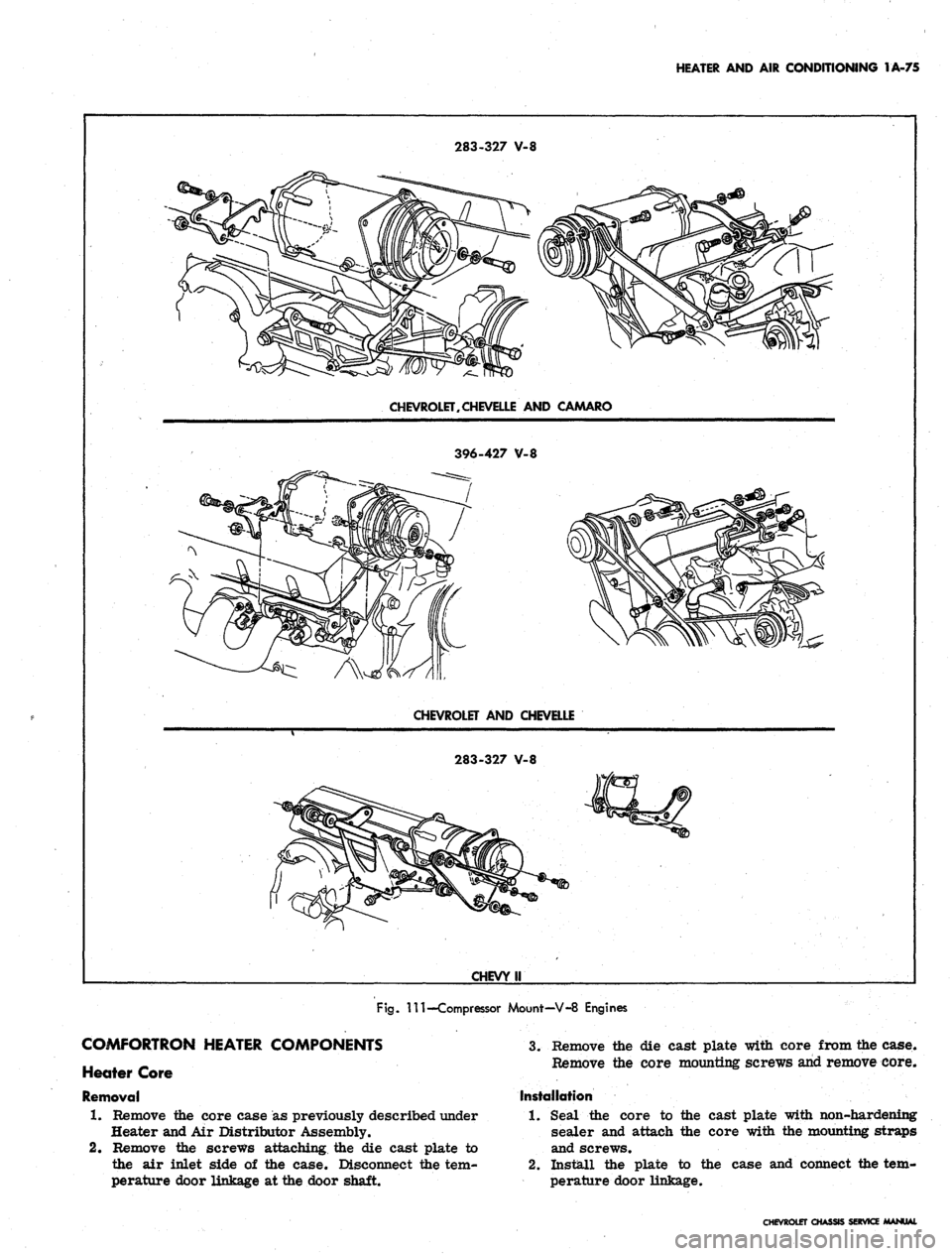
5. Remove the nuts and bolts attaching the compressor
brackets to the mounting bracket.
6. Before beginning any compressor disassembly, drain
and measure oil in the compressor. Check for
evidence of contamination to ..determine if remainder
of system requires servicing. Compressor Servicing
information is located in the Chassis Overhaul
Manual.
Installation
1.
li oil previously drained from the compressor upon
removal shows no evidence of contamination, replace
a like amount of fresh refrigeration oil into the com-
pressor before reinstallatLon. If it was necessary to
service the entire system because of excessive con-
tamination in the oil removed, install a full charge of
"fresh refrigeration oil in the compressor. (See
Checking Compressor Oil Charge under Checking
Oil)
2.
Position compressor on the mounting bracket and
install all nuts, bolts and lock washers.
3.
Install the connector assembly to the compressor
rear head, using new "O" rings.
4.
Connect the electrical lead to the coil and install
and adjust compressor belt.
5. Evacuate and charge the system.
6. Leak test the system and check for proper operation.
Fig.
113—Heater Hoses^-Four-Season System (Corvette)
CHEVROLET CHASSIS SERVICE MANUAL
Page 100 of 659
HEATER AND AIR CONDITIONING 1A-77
Compressor Belt Tension Adjustment
Adjust the compressor belt to the specifications shown
in the Tune-Up chart in the Engine section of this manual.
COMPRESSOR FAILURE
If the compressor has failed mechanically to the ex-
tent that metal chips and shavings are found in it, the
system should be checked for foreign material and
cleaned as described under Foreign Material in the
System.
CHEVROLET CHASSIS SERVICE MANUAL