CHEVROLET CAMARO 1967 1.G Chassis Workshop Manual
Manufacturer: CHEVROLET, Model Year: 1967, Model line: CAMARO, Model: CHEVROLET CAMARO 1967 1.GPages: 659, PDF Size: 114.24 MB
Page 101 of 659

HEATER AND AIR CONDITIONING 1A-78
WIRING DIAGRAMS
Blower
Motor
Resistor
•
Asm
EVAPORATOR—v
ASM.
\
-Diode
(Arc I
suppressor)
^\
16B
—>
-COMPRESSOR
Clutch Coil
•To battery positive
(+) terminal
No vacuum
in hose
#3
Blower
intake
air
Outside
air entry
Valve
by vacuum
in
hose
#3
Valve
normally
closed (spring
held)
Inside
car
air
(Recirc.)
AIR INLET
VALVE
POSITION:
Outside
air
intake
Recirc. air'intake
CONTROL ASM
TEMP CONTROL LEVER
(Operates temp valve
cable
&
equipment
in
chart shown below)
Compressor
Sw.
(Normally closed
Temp valve
begins
to
open
valveV
cable
arm
•Fan Speed Selector Switch
Switch
lever
position
Off
Low
Med
High
Contacts
made
B
to
None
BtoL
B to L
&
M
B to
L
& H
Fan
speed
Low
Low
Med
High
Resistance
in series with
Bio Motor
Hi
Rl
(RiR2)/(Rl+R2)
None
•Blower switch contacts must
be
dosed
before
fan
switch will
be
operable.
COLD
(O.
A.)
COLD a.A.)
Blower
H
y—low
switch
M/
-med
(Norm,
closed
contacts)
Fan speed switch
(See chart
at
left)
To vacuum,
tank
EXTENSION—vy
Horn relay "Bat" WIRE
ASM
X
harness
terminal
V
.**-__.. ;_
1 I panel
Legend:
___. —
Production wiring
Wire
is
part
of
equip.
•—————* Air
conditioning
wrg.
| i
T Agn. sw.
accsy
I term.
I
Temp
Control
Lever
Position
OFF
VENT.
COLD(I.A.)
COLEKO.AJ
HOT
Blower
(Master)
switch
contacts
Open
Closed
Closed
Closed
Closed
Vac switch
connects
vac source
to hose
#
#2
#2
&
#3
None
#3
#2
&
#3
Compressor
switch
contacts:
Open
Open
Closed
Closed
Open
Blower
intake
air
Outside
car air
intake used
Inside
car air
recirculated
Outside
car air
intake used
.Outside
car air
intake used
Fig. 114—Chevrolet—Four-Season Wiring Diagram
CHEVROLET CHASSIS SERVICE MANUAL
Page 102 of 659
HEATER
AND AIR CONDITIONING IA-79
BAT.
CABLE
ASM
A/C
wrg fwd of
dash
exc
bat.
cables,
ext
wire
&
compressor
grd
wire
is
part
of engine wiring harness.
"COMPRESSOR"
SW:
"OFF" POSN
"ON"
POSN
RELAY
ASM
/-DASH
/
PANEL
RESISTOR
ASM
LUTCH
COIL
:OMI
GRD
WIRE
ASM
MPRESSOR
BAT.
TERM
ON START
MTR SOL
EXTENSION WIRE ASM
._
J
J
^-CONTROL
SW
CONTACTS
B TO NONE
BTOL
BTOL&M
BTOL6H
•IGN SW ACCSY TERM.
A/C wrg
to
rear
of
dash
of
inst pnl harness.
Fig.
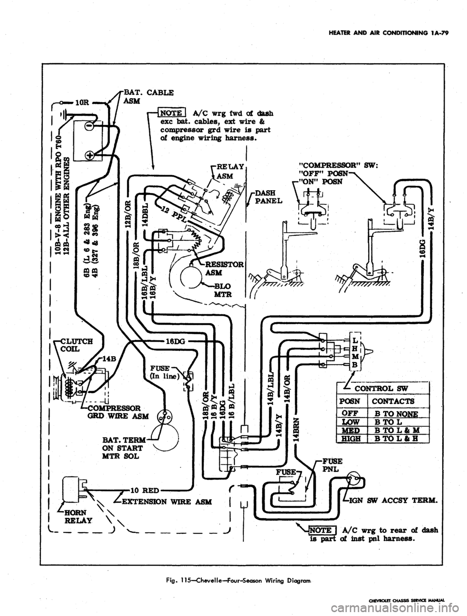
115—CheveIle—Four-Season Wiring Diagram
CHEVROLET
CHASSIS SERVICE MANUAL
Page 103 of 659

HEATER
AND AIR
CONDITIONING
1A-80
EVAPORATOR ASM.
Blower
Motor
INSIDE VALVE
(Normally closed
-spring held)
PLENUM VALVE
(Normally open
-spring held)
Actuator
(Vacuum
operated)
Inside car air (Recirc*
CONTROL ASM
TEMP CONTROL LEVER
•(Operates temp valve
cable
&
equipment in
hart shown below)
Temp valve
begins to
16DG
Fuse (In-line^
COMPRESSOR
Clutch Coil DASH-
PANEL
•Fan Speed Selector Switch
Switch
lever
position
Off
Low
"HeST
High
Contacts
B to
None
BtoL
B to L b U
BtoL&H
Fan
speed
Low
Low
Med
High
Resistance
in series with
Bio Motor
Rl
Rl
RlR2)/(Rl+R2)
None
•Blower switch contacts must be closed
before fan switch will be operable.
-To battery positive
(-0 terminal
•
Horn relay
terminal"
"Batf
To vacuum
tank
EXTENSION
WIRE
ASM
(Normally closed
contacts-*vac
operated)
7
*- Fan speed switch
(See chart at left)
•/-Wire is
\ part of
I inst panel
harness
Legend:
— Production wiring
————
Wire Is part of equip.
•mmmmmmmmmmmmmm*
AIT
Conditioning
WTg*
Temp
Control
Lever
Position
OFF
VENT
COLD
a.A.)
COLD
(O.A.)
HOT
Blower
(Master)
switch
contacts
Open
Closed
Closed
Closed
Closed
Vac switch
connects
vac source
to hose #
#2
&
#3
#2
#3
None
#2
Compressor
switch
contacts^
Open
Open
Closed
Closed
Open
Blower
intake air
Outside car air
intake used
Inside car air
recir culated
Outside car air
intake used
Outside car air
intake used
Fig.
116—Camaro—Four-Season Wiring Diagram
CHEVROLET CHASSIS SERVICE
Page 104 of 659
HEATER AND AIR CONDITIONING 1A-81
HORN RELAY
r
CONN.-
14 BROWN
(TO FUSE
PANEL)
BATTERY
1
—I ^ COMPR
ESSOR
DASH y
V-^ PANEL \
GROMMET—%
1 \
_ J~ ") "^
>14 BLACK/RED STRIPE-
FUSE .20 AMP.
•WIRE ASM. BLOWER-
MOTOR
14 BLACK 1
IGNITION SWITCH1
(ACCESSORY
TERMINAL)
CONTROL SWITCH
-RESISTOR
CONN.
•14 TAN
•16 BLACK
LIGHT BLUE STRIPE
•THERMOSTAT CONTROL
EVAPORATOR & BLOWER ASM.
Fig.
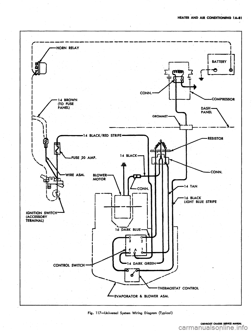
117—Universal System Wiring Diagram (Typical)
CHEVROLET CHASSI
Page 105 of 659
HEATER AND AIR CONDITIONING 1A-82
•BATTERY
(POS)
CABLE
NOTE
When
control
switch*
is !TOFF"
&
Air
Cond
is
"ON"
(Control
knob
pulled
but) the
blower
fan'will
run at low
speed.
CONTROL
SWITCH
CONNECTIONS
OFF
LOW
MED
HIGH
B
TO
NONE
B
TO L
BTOL&M
B
TO L
&
H
COMPRESSOR
GROUND
WIRE
ASM
BATTERY
(NEGATIVE)
CABLE
COMPRESSOR
ASM
DASHPAJSTEL
GROMMET
16DG
CONTROL
SWITCH
RESISTOR
ASM
14LBL
14BRN
CLUTCH
COIL
EXTENSION
WIRE
ASM
-14BRN--N
JUNC
BLOCKi
OSTATIC
SWITCH
CONTACTS
NORMALLY
CLOSED
STARTING
MOTOR
SOLENOID
BLOWER
MOTOR
AIR
COND
CONTROL
(PUSH-PULL)
KNOB
DOOR
SWITCH
(PUSH
BUTTON
NORMALLY
CLOSED)
RELAY
ASM
HORN
RELAY
DIVERTER
DOOR CABLE
FUSE
PANEL
EVAPORATOR
ASM
IGNITION SWITCH-
ACCESSORY TERMINAL)
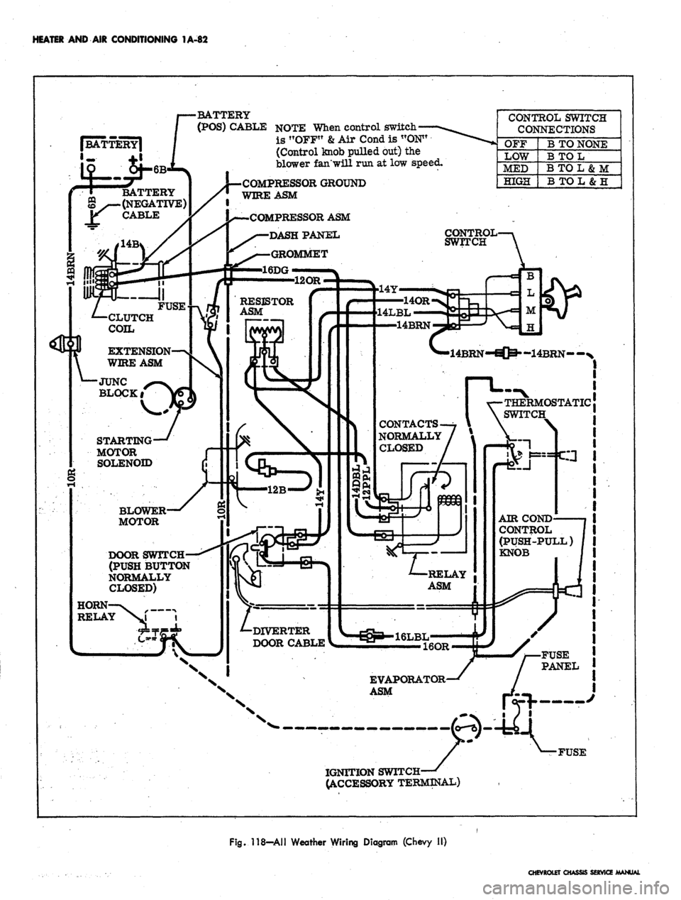
Fig. 118—All Weather Wiring Diagram (Chevy II)
CHEVROLET CHASSIS SERVICE MANUAL
Page 106 of 659
HEATER AND AIR CONDITIONING 1A-83
DIVERTER DOOR
CRANK POSITIONS:
AIR COND "ON"
AIR COND "OFF*
AIR COND SWITCH
(PUSH BUTTON,
NORMALLY CLOSED
CONTACTS)
BLOWER MOTOR
CONTACTS
NORMALLY
4D
16
16B/Y
COMPRESSOR
GROUND WIRE
ASM
BAT.
TERMINAL
ON STARTING
MOTOR SOLENOID
' BATTERY
CABLE ASM:
NEGATIVE
POSITIVE—*
- CONTROL SWITCH
SET AT:
•OFF
LOW
MED
HIGH
CONTACTS:
BTOBL
BTOL
BTOM
BT0M6B,
CLUTCH
HOUSING
liOli: WHEN CONTROL
SWITCH IS AT "OFF" &
AIR COND. IS "ON", FAN
WILL RUN AT LOW SPEED.
"AIR COND-PULL"
KNOB (SHOWN IN "ON"
POSITION)
TO REGULATOR
HORN
RELAY
16 BRN-BODY WIRING
HARNESS-837
14BRN
I
^
IA^RN
* IGNITION SWITCH
« 12R ACCESSORY TERMINAL
12R f
AMMETER
LEGEND:
AIR COND WIRING (PART OF
ENGINE WIRING HARNESS)
WIRING IS PART OF EQUIP
REG PRODUCTION WIRING
Fig.
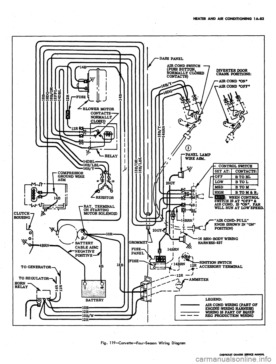
119—Corvette—Four-Season Wiring Diagram
CHEVROLET CHASSIS SERVICE MANUAL
Page 107 of 659
HEATER
AND AIR
CONDITIONING
1A-84
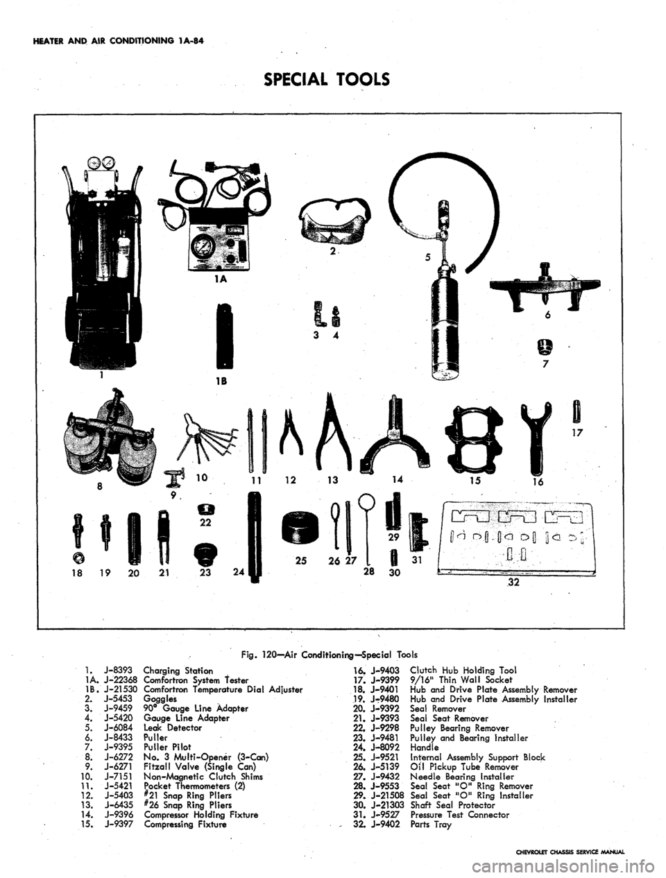
SPECIAL TOOLS
18
19 20 21 23 24
28
30
32
Fig.
120—Air Conditioning—Special Tools
1.
1A.
IB.
2.
3.
4.
5.
6.
7.
00*
9.
10.
11.
12.
13.
14.
15.
J-8393
J-22368
J-21530
J-5453
J-9459
J-5420
J-6084
J-8433
J-9395
J-6272
J-6271
J-7151
J-5421
J-5403
J-6435
J-9396
J-9397
Charging Station
Comfortron System fester
Comfortron Temperature Dial Adjuster
Goggles
90° Gauge Line Adapter
Gauge Line Adapter
Leak Detector
Puller
Puller Pilot
No.
3
Multi-Opener (3-Can)
Fitzall Valve (Single
Can)
Non-Magnetic Clutch Shims
Pocket Thermometers
(2)
#21 Snap Ring Pliers
#26 Snap Ring Pliers
Compressor Holding Fixture
Compressing Fixture
16.
J-9403
17.
J-9399
18.
J-9401
19.
J-9480
20.
J-9392
21.
J-9393
22.
J-9298
23.
J-9481
24.
J-8092
25.
J-9521
26.
J-5139
27.
J-9432
28.
J-9553
29.
J-21508
30.
J-21303
31.
J-9527
,
32.
J-9402
Clutch
Hub
Holding Tool
9/16" Thin Wall Socket
Hub
and
Drive Plate Assembly Remover
Hub
and
Drive Plate Assembly Installer
Seal Remover
Seal Seat Remover
Pulley Bearing Remover
Pulley and Bearing installer
Handle
Internal Assembly Support Block
Oil Pickup Tube Remover
Needle Bearing Installer
Seal Seat "O" Ring Remover
Seal Seat "O" Ring Installer
Shaft Seal Protector
Pressure Test Connector
Parts Tray
CHEVROLET CHASSIS SERVICE MANUAL
Page 108 of 659
SECTION
IB
CORVETTE BODY
INDEX
Page
General Description . . * • •.
•
^"i1
Maintenance and Replacements 1B-1
Front End 1B-1
Adjustments IBri
Hood 1B-1
Hood Catch 1B-2
Hood Assembly . 1B-2
Front Emblems 1B-2
Vent Grilles 1B-2
Instrument Panel Tray . 1B-2
Cowl Area Trim
....................
1B-4
Rear View Mirror 1B-4
Outside 1B-4
Inside . 1B-4
Sun Visor . 1B-4
Cowl Ventilator Assembly 1B-4
Windshield ; 1B-5
Doors 1B-7
Adjustments 1B-7
Door Lock Striker 1B-7
Door Window and Vent 1B-7
Door Hinges 1B-7
Trim Panel and Inside Handles IB-11
Weatherstrip 1B-11
Door Ventilator Assembly 1B-12
19437 Model 1B-12
19467 Model 1B-13
Window Glass 1B-13
Glass Run Channel—Upper 1B-14
Window Outer Seal Assembly 1B-14
Window Inner Seal Assembly 1B-14
Glass Run Channel—Rear 1B-15
Window Regulator—Manual 1B-15
Window Regulator—Power 1B-15
Door Lock and Remote Controls 1B-16
Outer Handle . 1B-16
Lock Cylinder 1B-17
Hinges—Door Assembly . 1B-17
Rear Quarter .. . 1B-19
Door Sill and Molding . . 1B-19
Rear End . . r 1B-19
Folding Top Compartment Lid 1B-19
Adjustments . . 1B-19
1B-19
Page
Lock 1B-19
Control 1B-19
Rear Window—19437 Model 1B-21
Gas Tank Door and Rear Trim Plate.,. . . . . . . . 1B-23
Rear Filler Panel 1B-23
Spare Tire Mount 1B-23
Rugs and Interior Trim 1B-25
Cleaning Soft Trim 1B-25
Carpets and Covers—All Models 1B-26
Rear Body Trim , . 1B-26
Soft Covers 1B-26
Rigid Plastic Trim 1B-26
Garnish Moldings Plus-Headliner-19437 Model . . 1B-27
Seats 1B-27
Body Mounting 1B-27
Body Repairs . 1B-27
General Instructions . . . 1B-27
Repair Panels. 1B-28
Precautions 1B-29
Plastic Solder Kit 1B-29
Resin Kit 1B-30
Specific Repairs 1B-32
Scratched Panels-Spot Refinishing 1B-32
Dents in Panels-Surface Cracks !B-33
Cracked Panels . . 1B-35
Fractures 1B-37
Panel Replacement 1B-39
Hard Top . . 1B-41
Care and Storage 1B-41
Rear Window 1B-41
Garnish Moldings and Latches 1B-42
Headlining 1B-43
Weatherstrips and Drip Molding 1B-43
Vinyl Covering . 1B-43
Folding Top 1B-46
Care of Folding Top 1B-46
Care of Rear Window 1B-46
Adjustments 1B-48
Top Assembly, Removal and Installation 1B-49
Top Trim and Rear Window Assembly 1B-50
Frame and Linkage 1B-52
Weatherstrip 1B-52
Adding Hardtop 1B-52
Special Tools 1B-53
GENERAL DESCRIPTION
.
A
structural network
of
steel forms the backbone
of
the
Corvette body. When combined with
the
fiber-glass
re-
inforced plastic body panels,
the
steel-plastic marriage
results
in a
body with increased torsional rigidity
and
greater beaming strength.
Convertible models continue with two roof styles:
the
folding
top
and the removable hardtop. In operation, both
tops function similar to those
of
previous models. Either
top
is
standard and both
are
optional
as
determined by
the top selected
as
base equipment.
MAINTENANCE
&
REPLACEMENTS
FRONT
END
ADJUSTMENTS
(Refer to Figure
2)
Adjustments should
be
made
in
order
-
hood position
first, then catch adjustments.
Hood
The position
of the
hood
in
relation
to
the hood body
opening and the fender surfaces
is
controlled by the posi-
tion
of the
hinges and position
and
adjustment
of
catch
and bumpers.
The fore
and aft
position
of the
hood may be adjusted
CHEVROLET CHASSIS SERVICE MANUAL
Page 109 of 659
CORVETTE BODY 1B-2
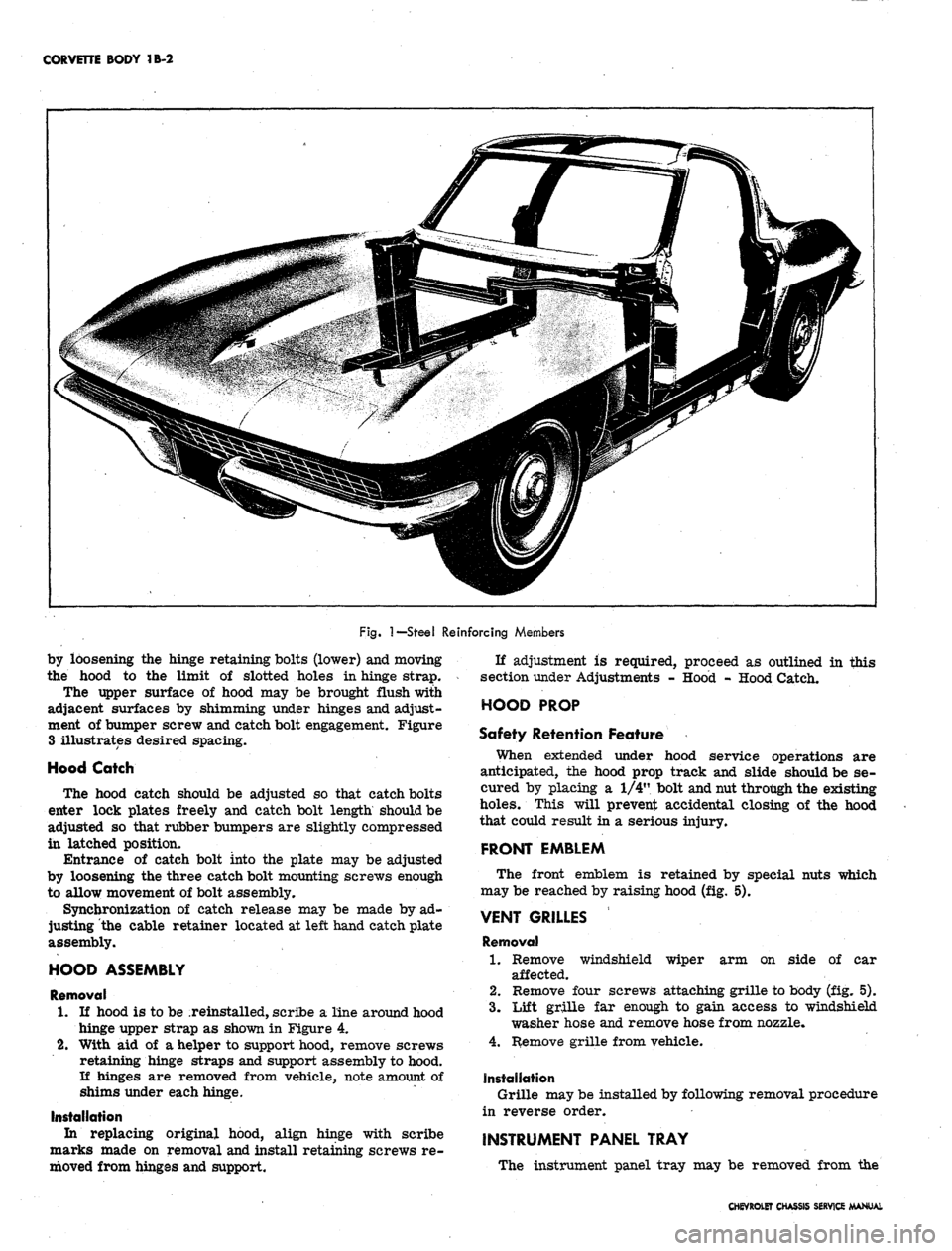
Fig.
1—Steel
Reinforcing Members
by loosening the hinge retaining bolts (lower) and moving
the hood to the limit of slotted holes in hinge strap.
The upper surface of hood may be brought flush with
adjacent surfaces by shimming under hinges and adjust-
ment of bumper screw and catch bolt engagement. Figure
3 illustrates desired spacing.
Hood Catch
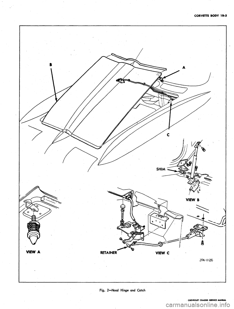
The hood catch should be adjusted so that catch bolts
enter lock plates freely and catch bolt length should be
adjusted so that rubber bumpers are slightly compressed
in latched position.
Entrance of catch bolt into the plate may be adjusted
by loosening the three catch bolt mounting screws enough
to allow movement of bolt assembly.
Synchronization of catch release may be made by ad-
justing the cable retainer located at left hand catch plate
assembly.
HOOD ASSEMBLY
Removal
1.
If hood is to be reinstalled, scribe a line around hood
hinge upper strap as shown in Figure 4.
2.
With aid of a helper to support hood, remove screws
retaining hinge straps and support assembly to hood.
If hinges are removed from vehicle, note amount of
shims under each hinge.
Installation
In replacing original hood, align hinge with scribe
marks made on removal and install retaining screws re-
moved from hinges and support.
If adjustment is required, proceed as outlined in this
section under Adjustments - Hood - Hood Catch.
HOOD PROP
Safety Retention Feature
When extended under hood service operations are
anticipated, the hood prop track and slide should be se-
cured by placing a 1/4" bolt and nut through the existing
holes.
This will prevent accidental closing of the hood
that could result in a serious injury.
FRONT EMBLEM
The front emblem is retained by special nuts which
may be reached by raising hood (fig. 5).
wiper arm on side of car
VENT GRILLES
Removal
1.
Remove windshield
affected.
2.
Remove four screws attaching grille to body (fig. 5).
3.
Lift grille far enough to gain access to windshield
washer hose and remove hose from nozzle.
4.
Remove grille from vehicle.
Installation
Grille may be installed by following removal procedure
in reverse order.
INSTRUMENT PANEL TRAY
The instrument panel tray may be removed from the
CHEVROLET CHASSIS SERVICE MANUAL
Page 110 of 659
CORVETTE BODY
1B-3
VIEW
A
RETAINER
VIEW
C
2PA-II-26
Fig.
2—Hood Hinge
and
Catch
CHEVROLET
O-