CHEVROLET CAMARO 1982 Repair Guide
Manufacturer: CHEVROLET, Model Year: 1982, Model line: CAMARO, Model: CHEVROLET CAMARO 1982Pages: 875, PDF Size: 88.64 MB
Page 321 of 875
GM – CAMARO 1982-1992 – Repair Guide (Checked by WxMax) 321
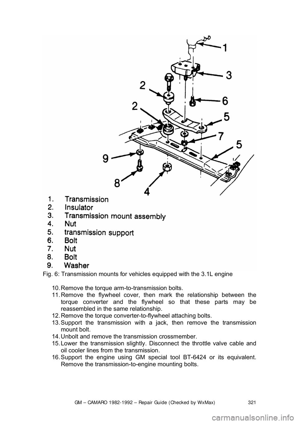
Fig. 6: Transmission mounts for vehi cles equipped with the 3.1L engine
10. Remove the torque arm-to-transmission bolts.
11. Remove the flywheel cover, t hen mark the relationship between the
torque converter and the flywheel so that these parts may be
reassembled in the same relationship.
12. Remove the torque converter-t o-flywheel attaching bolts.
13. Support the transmission with a ja ck, then remove the transmission
mount bolt.
14. Unbolt and remove the transmission crossmember.
15. Lower the transmission slightly. Disco nnect the throttle valve cable and
oil cooler lines from the transmission.
16. Support the engine using GM specia l tool BT-6424 or its equivalent.
Remove the transmission- to-engine mounting bolts.
Page 322 of 875

GM – CAMARO 1982-1992 – Repair Guide (Checked by WxMax) 322
CAUTION - The transmission must be secu red to the transmission jack
17. Remove the transmission from the vehicle. Be careful not to damage the oil cooler lines, throttle valve cable, or the shift control cable. Also, keep
the rear of the transmissi on lower than the front to avoid the possibility of
the torque converter disengagi ng from the transmission.
To install: 18. Position the transmission and converter into place.
19. Install the transmission -to-engine mounting bolts.
20. Connect the throttle valve cable and oil cooler lines to the transmissio\
n.
21. Install the transmission cro ssmember and secure with bolts.
22. Install the transmission mount bolt.
23. Matchmark the torque converter-to-f lywheel. Install the torque converter-
to-flywheel attaching bolts.
Before installing the converter-to-flywheel bolts, be sure that the weld nuts on
the converter are flush with the flywheel, and that the converter rotates freely by
hand in this position.
24. Install the flywheel cover.
25. Install the torque arm-to-transmission bolts.
26. Connect the speedometer cable, el ectrical connectors and the shift
control cable from the transmission.
27. Connect the catalytic converter s upport bracket at the transmission.
28. Align the matchmark m ade earlier, then install the driveshaft to the axle
pinion. Bolt the universal joint straps to the pinion flange.
29. Lower the vehicle.
30. Install the dipstick tube using a ne w dipstick tube O-ring and secure with
the bolt. Install the tran smission oil dipstick.
31. Connect the throttle valve (TV) c ontrol cable at the carburetor.
32. Install the air cleaner assembly.
33. Connect the negative battery cable at the battery.
DRIVELINE
DRIVESHAFT AND U-JOINTS
The U-joint is secured to the yoke in one of two ways. Dana and Cleveland
shafts use a conventional snapring to ho ld each bearing cup in the yoke. The
snapring fits into a groove located in eac h yoke end just on top of each bearing
cup. The Saginaw design shaft secures its U-joints in another way. Nylon
material is injected through a small hole in the yoke and flows along a circular
groove between the U-joint and the yoke , creating a synthetic snapring.
Disassembly of the Saginaw U-joint requi res the joint to be pressed from the
yoke. This results in damage to the be aring cups and destruction of the nylon
rings.
Page 323 of 875
GM – CAMARO 1982-1992 – Repair Guide (Checked by WxMax) 323
Replacement kits include new bearing
cups and conventional snaprings to
replace the original nylon rings. These replacement rings must go inboard of the
yoke in contrast to outboard mounting of the Dana and Cleveland designs.
Previous service to the Saginaw U-joints can be recognized by the presence of
snaprings inboard of the yoke.
Bad U-joints, requiring replacement, will produce a clunking sound when the car
is put into gear. This is due to worn needle bearings or a scored trunnion end
possibly caused by improper lubricati on during assembly. Camaro U-joints
require no periodic maintenance and theref ore have no lubrication fittings.
DRIVESHAFT
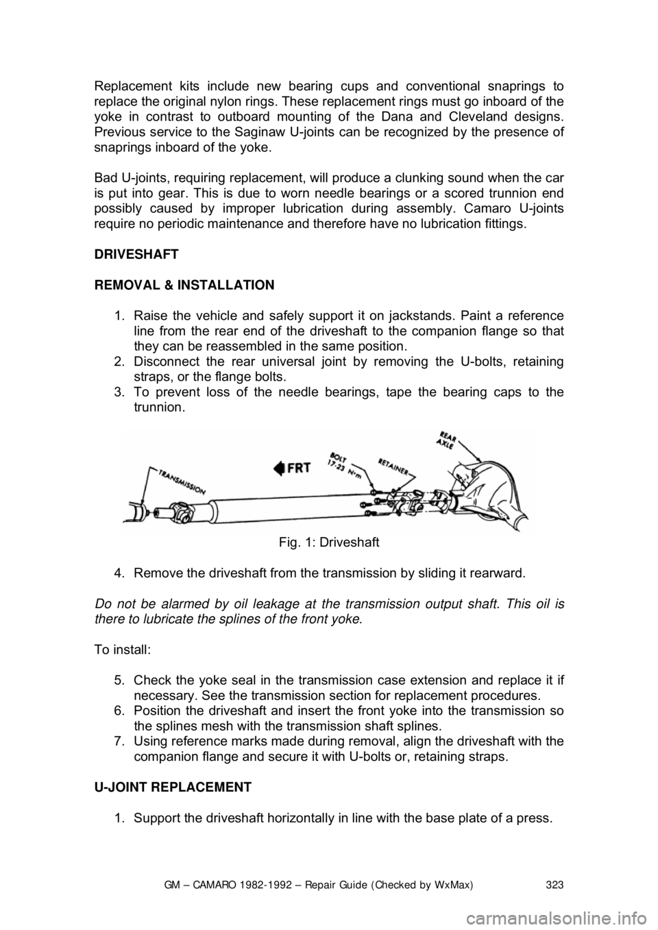
REMOVAL & INSTALLATION 1. Raise the vehicle and safely su pport it on jackstands. Paint a reference
line from the rear end of the drives haft to the companion flange so that
they can be reassembled in the same position.
2. Disconnect the rear universal join t by removing the U-bolts, retaining
straps, or the flange bolts.
3. To prevent loss of the needle bear ings, tape the bearing caps to the
trunnion.
Fig. 1: Driveshaft
4. Remove the driveshaft from the tr ansmission by sliding it rearward.
Do not be alarmed by oil l eakage at the transmission output shaft. This oil is
there to lubricate the sp lines of the front yoke.
To install: 5. Check the yoke seal in the transmi ssion case extension and replace it if
necessary. See the transmission sect ion for replacement procedures.
6. Position the driveshaft and insert t he front yoke into the transmission so
the splines mesh with the transmission shaft splines.
7. Using reference marks made during re moval, align the driveshaft with the
companion flange and secure it with U-bolts or, retaining straps.
U-JOINT REPLACEMENT 1. Support the driveshaft horizontally in line with the base plate of a press.
Page 324 of 875
GM – CAMARO 1982-1992 – Repair Guide (Checked by WxMax) 324
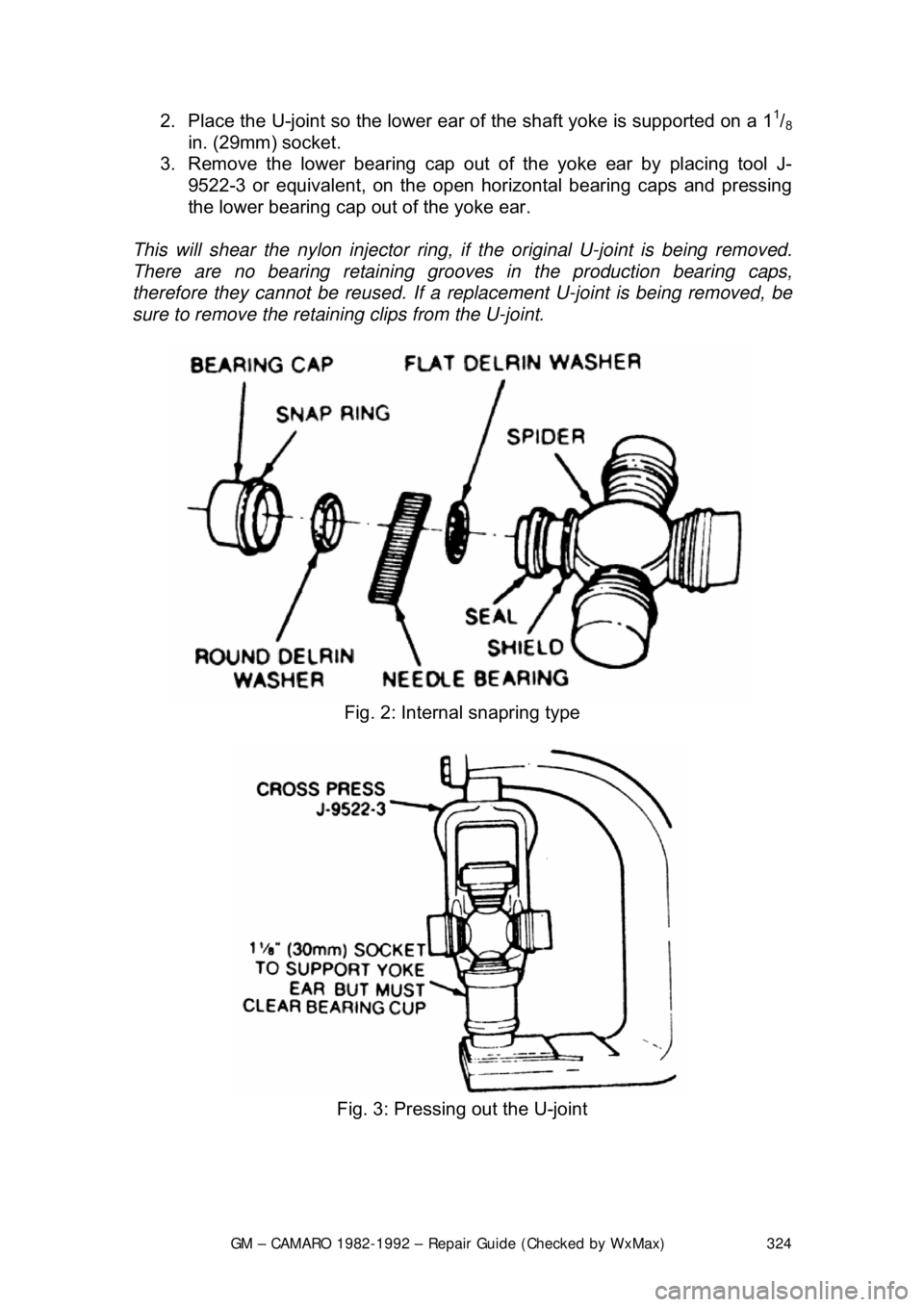
2. Place the U-joint so the lower ear
of the shaft yoke is supported on a 11/8
in. (29mm) socket.
3. Remove the lower bear ing cap out of the yoke ear by placing tool J-
9522-3 or equivalent, on the open horiz ontal bearing caps and pressing
the lower bearing cap out of the yoke ear.
This will shear the nylon injector ring, if the original U-joint is being removed.
There are no bearing re taining grooves in the production bearing caps,
therefore they cannot be reus ed. If a replacement U-joint is being removed, be
sure to remove the retaining clips from the U-joint.
Fig. 2: Internal snapring type
Fig. 3: Pressing out the U-joint
Page 325 of 875
GM – CAMARO 1982-1992 – Repair Guide (Checked by WxMax) 325
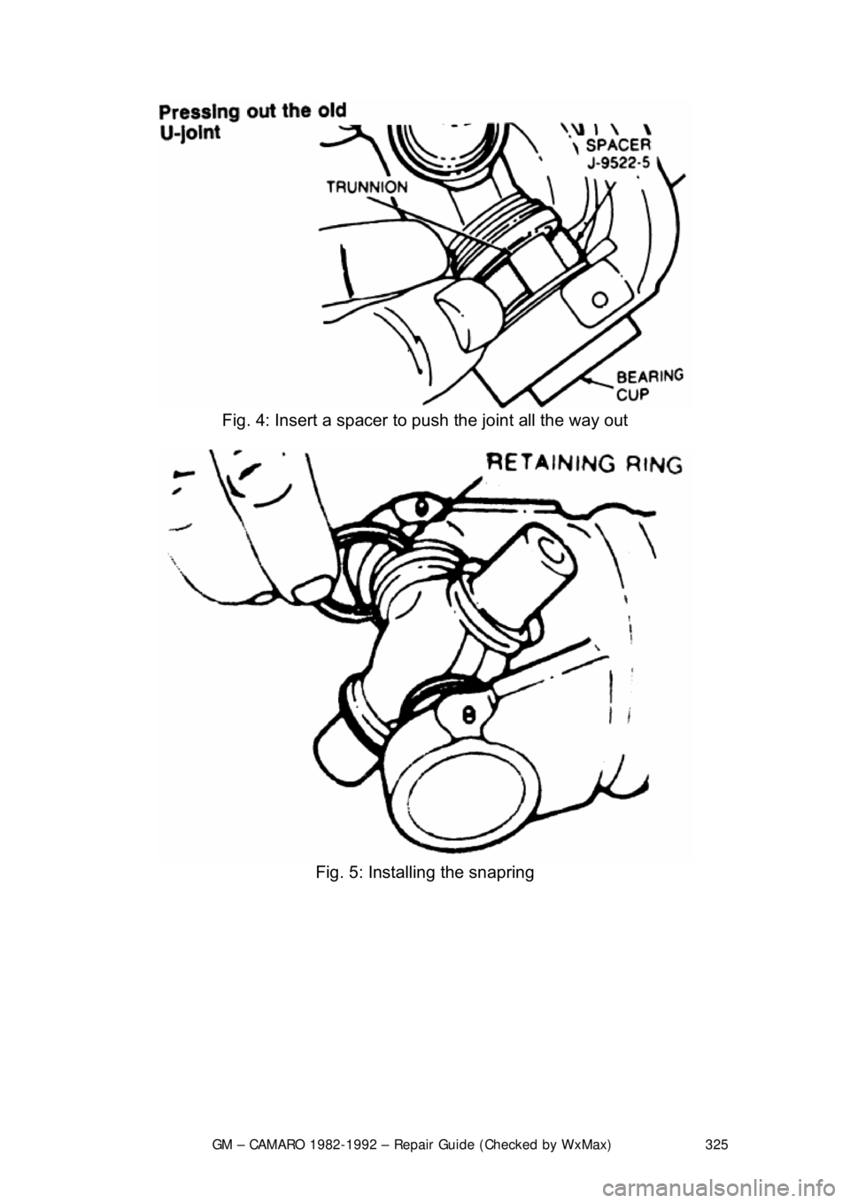
Fig. 4: Insert a spacer to push the joint all the way out
Fig. 5: Installing the snapring
Page 326 of 875
GM – CAMARO 1982-1992 – Repair Guide (Checked by WxMax) 326
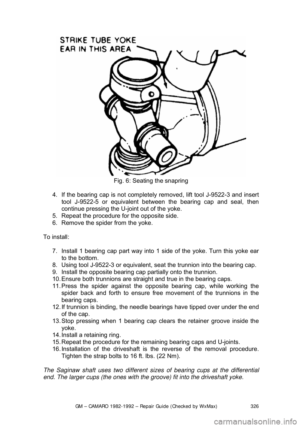
Fig. 6: Seating the snapring
4. If the bearing cap is not completely removed, lift tool J-9522-3 and insert
tool J-9522-5 or equivalent between the bearing cap and seal, then
continue pressing the U-jo int out of the yoke.
5. Repeat the procedure fo r the opposite side.
6. Remove the spider from the yoke.
To install: 7. Install 1 bearing cap part way into 1 side of the yoke. Turn this yoke ear
to the bottom.
8. Using tool J-9522-3 or equivalent, seat the trunnion into the bearing cap.
9. Install the opposite bearing c ap partially onto the trunnion.
10. Ensure both trunnions are straight and true in the bearing caps.
11. Press the spider agai nst the opposite bearing cap, while working the
spider back and forth to ensure free mo vement of the trunnions in the
bearing caps.
12. If trunnion is binding, the needle bearings have tipped over under the end
of the cap.
13. Stop pressing when 1 bearing cap clears the retainer groove inside the yoke.
14. Install a retaining ring.
15. Repeat the procedure for the rema ining bearing caps and U-joints.
16. Installation of the driveshaft is the reverse of the removal procedure.
Tighten the strap bolts to 16 ft. lbs. (22 Nm).
The Saginaw shaft uses two different si zes of bearing cups at the differential
end. The larger cups (the ones with the groove) fit into the driveshaft yoke.
Page 327 of 875
GM – CAMARO 1982-1992 – Repair Guide (Checked by WxMax) 327
REAR AXLE
IDENTIFICATION
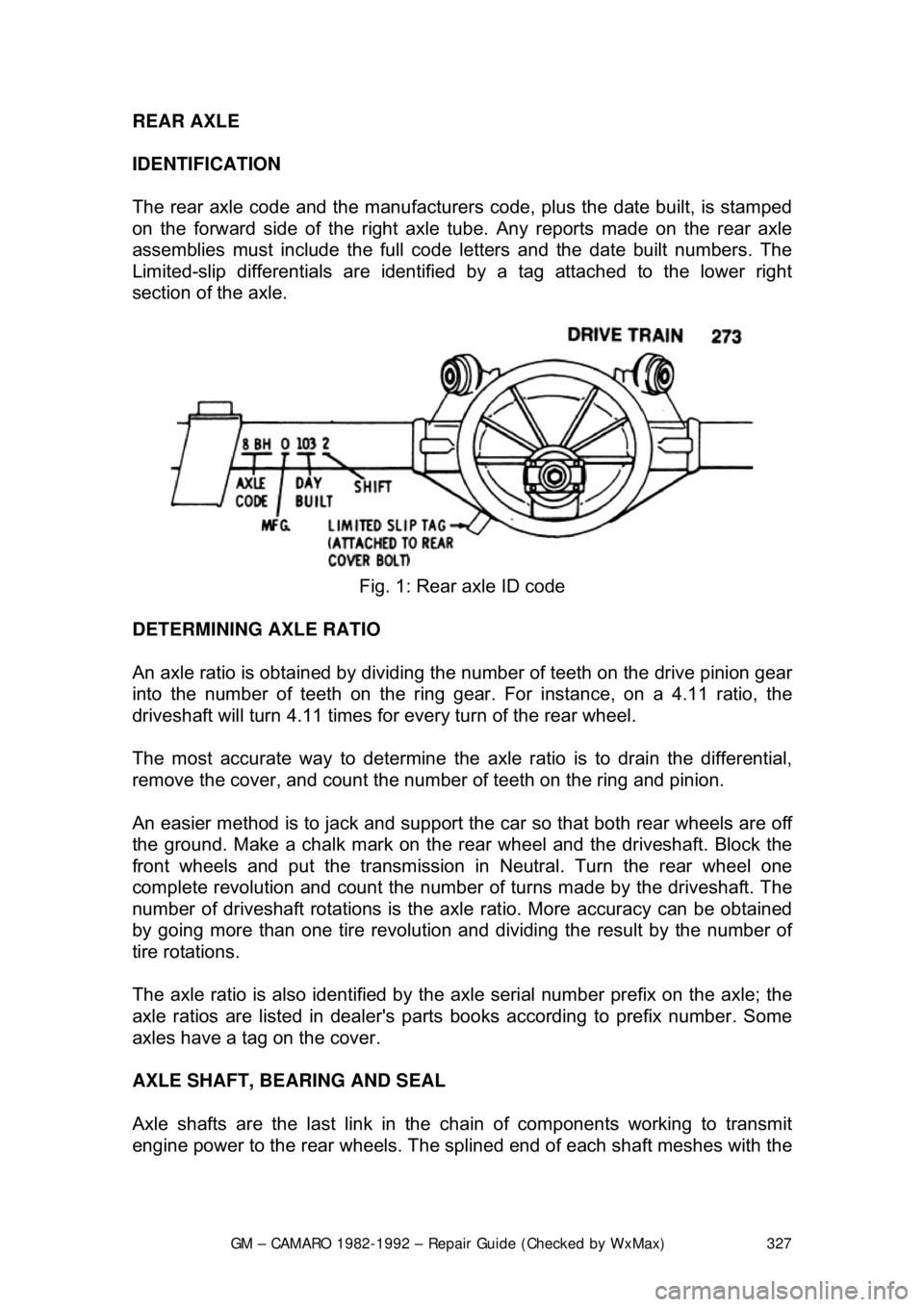
The rear axle code and the
manufacturers code, plus the date built, is stamped
on the forward side of the right axle tube. Any reports made on the rear axle
assemblies must include the full code le tters and the date built numbers. The
Limited-slip differentials are identified by a tag attached to the lower right
section of the axle.
Fig. 1: Rear axle ID code
DETERMINING AXLE RATIO
An axle ratio is obtained by dividing the number of teeth on the drive pinion gear
into the number of teeth on the ring gear. For instance, on a 4.11 ratio, the
driveshaft will turn 4.11 times for every turn of the rear wheel.
The most accurate way to determine the ax le ratio is to drain the differential,
remove the cover, and count the num ber of teeth on the ring and pinion.
An easier method is to jack and support th e car so that both rear wheels are off
the ground. Make a chalk mark on the r ear wheel and the driveshaft. Block the
front wheels and put the transmission in Neutral. Turn the rear wheel one
complete revolution and count the number of turns made by the driveshaft. The
number of driveshaft rotations is the ax le ratio. More accuracy can be obtained
by going more than one tire revolution and dividing the result by the number of
tire rotations.
The axle ratio is also identified by the ax le serial number prefix on the axle; the
axle ratios are listed in dealer's parts books according to prefix number. Some
axles have a tag on the cover.
AXLE SHAFT, BEARING AND SEAL
Axle shafts are the last link in the chain of components working to transmit
engine power to the rear wheels. The sp lined end of each shaft meshes with the
Page 328 of 875
GM – CAMARO 1982-1992 – Repair Guide (Checked by WxMax) 328
internal splines of each differential side
gear. As the side gears turn, so do the
axle shafts, and, since they are also connected, so do the wheels.
Each shaft passes through the side gear and is locked into place by either a C-
lock or flange plate bolted to the end of the axle housing with pressed on
bearings. As the name implies, the C-lock is a flat, C-shaped piece of metal that
fits into a groove at t he end of the shaft. A round pinion shaft is wedged in
between the end of the shafts. This pinion shaft prevents the shafts from sliding
inward and makes the C-locks functional by pushing them tightly against each
side gear. Removing this pini on shaft allows the shafts to slide inward making
the C-locks accessible for removal. Once the C-locks are removed, the axle
shafts can be pulled from the car.
The wheel end of each shaft is flanged and pressed into it are five wheel lug
bolts serving to hold on t he wheel. Each axle shaft is supported by an axle
bearing (wheel bearing) and oil seal located within the axle shaft housing just to
the outside of the br ake backing plate.
REMOVAL & INSTALLATION
EXCEPT BORG-WARNER REAR ASSEMBLY 1. Raise and support the vehicle safe ly. Remove the rear wheels and
drums or rotors.
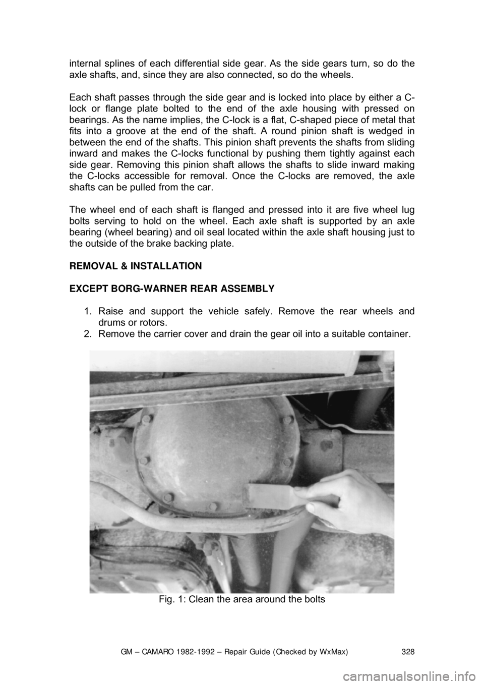
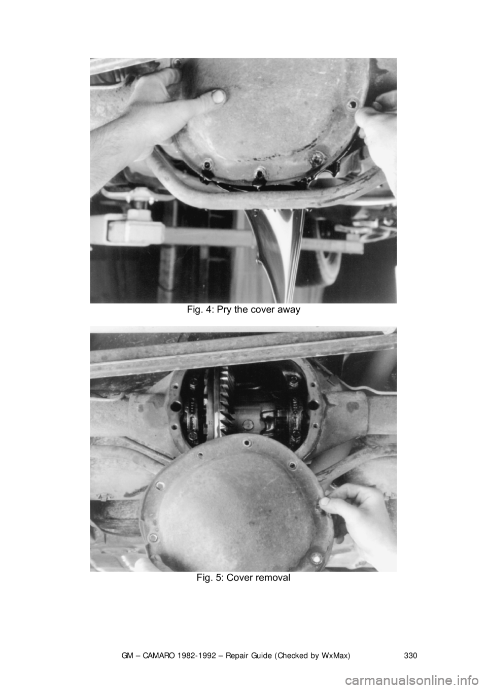
2. Remove the carrier cover and drain t he gear oil into a suitable container.
Fig. 1: Clean the area around the bolts
Page 329 of 875
GM – CAMARO 1982-1992 – Repair Guide (Checked by WxMax) 329
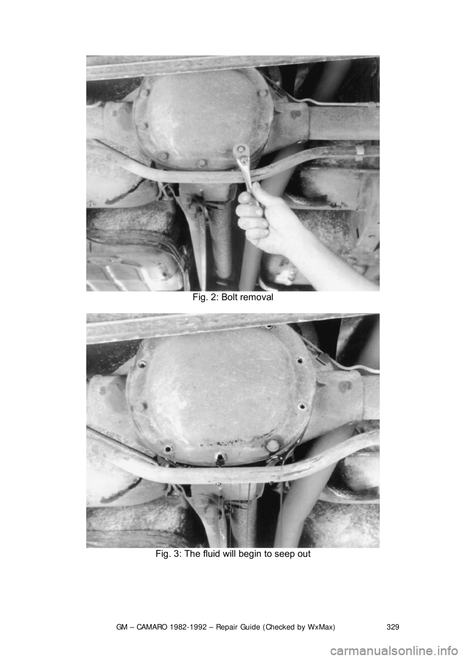
Fig. 2: Bolt removal
Fig. 3: The fluid will begin to seep out
Page 330 of 875
GM – CAMARO 1982-1992 – Repair Guide (Checked by WxMax) 330
Fig. 4: Pry the cover away
Fig. 5: Cover removal