CHEVROLET CAMARO 1982 Repair Guide
Manufacturer: CHEVROLET, Model Year: 1982, Model line: CAMARO, Model: CHEVROLET CAMARO 1982Pages: 875, PDF Size: 88.64 MB
Page 361 of 875
GM – CAMARO 1982-1992 – Repair Guide (Checked by WxMax) 361
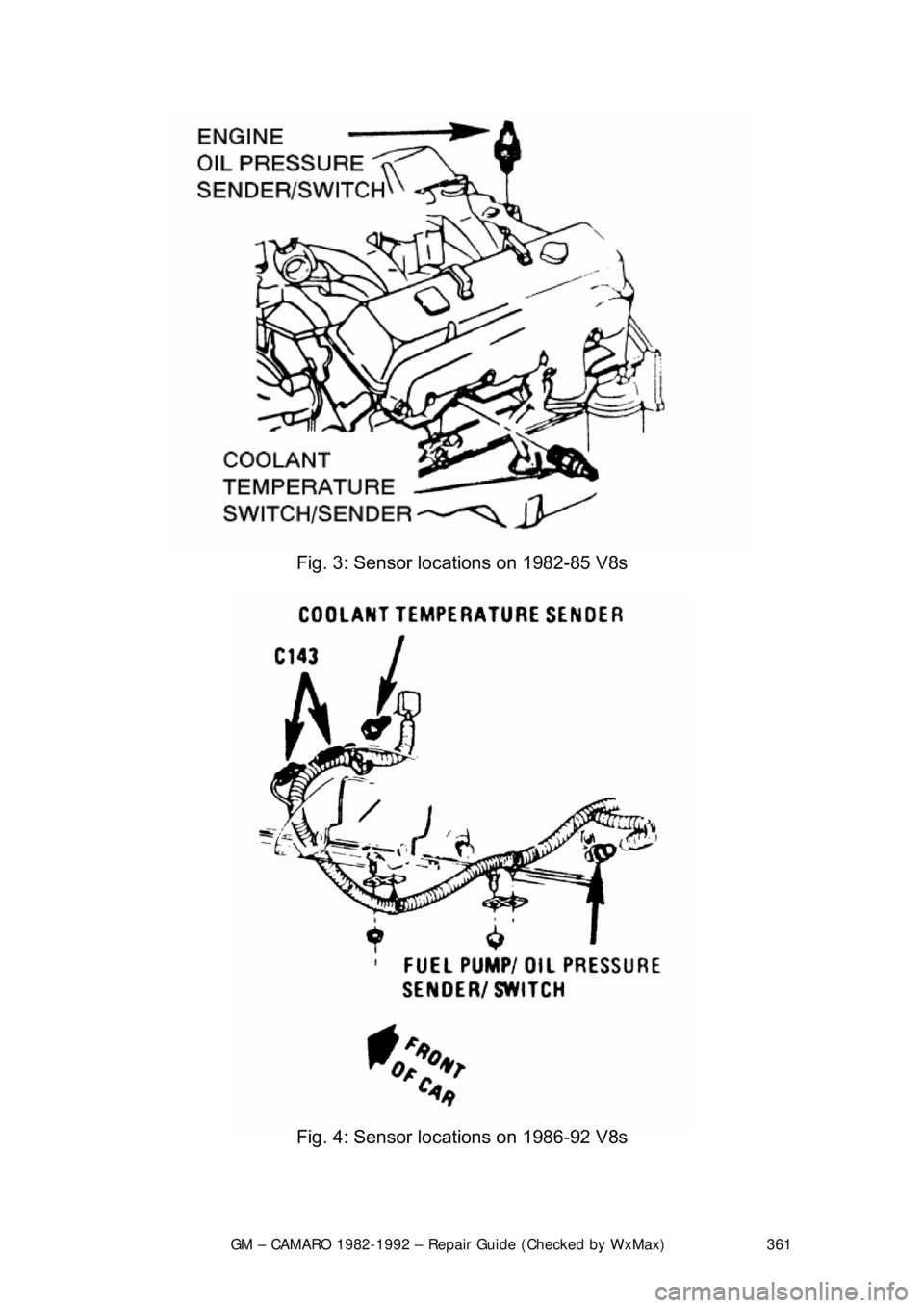
Fig. 3: Sensor locations on 1982-85 V8s
Fig. 4: Sensor locations on 1986-92 V8s
Page 362 of 875

GM – CAMARO 1982-1992 – Repair Guide (Checked by WxMax) 362
OIL PRESSURE SENDING UNIT
Replace the sending unit by disconnecting
the electrical connector and using a
special socket to remove it.
ENGINE
MECHANICAL ENGINE
REMOVAL & INSTALLATION
In the process of removing the engine, you will come across a number of steps
which call for the removal of a separ ate component or system, such as
"disconnect the exhaust system " or "remove the radiator." In most instances, a
detailed removal procedure can be found elsewhere in this repair guide.
It is virtually impossible to list each individual wire and hose which must be
disconnected, simply because so many different model and engine
combinations have been manufactured. Careful observation and common
sense are the best possible approaches to any repair procedure.
Removal and installation of the engine ca n be made easier if you follow these
basic points:
• If you have to drain any of the fl uids, use a suitable container.
• Always tag any wires or hoses and, if possible, the components they
came from before disconnecting them.
• Because there are so many bolts and fasteners involved, store and label
the retainers from com ponents separately in muffin pans, jars or coffee
cans. This will prevent conf usion during installation.
• After unbolting the transmission or trans axle, always make sure it is
properly supported.
• If it is necessary to disconnect t he air conditioning system, have this
service performed by a qualified tec hnician using a recovery/recycling
station. If the system does not have to be disconnected, unbolt the
compressor and set it aside.
• When unbolting the engine mounts, a lways make sure the engine is
properly supported. When removing t he engine, make sure that any
lifting devices are properly attached to the engine. It is recommended
that if your engine is supplied with lifting hooks, your lifting apparatus be
attached to them.
• Lift the engine from its compartment sl owly, checking that no hoses,
wires or other component s are still connected.
• After the engine is clear of the compar tment, place it on an engine stand
or workbench.
• After the engine has been removed, y ou can perform a partial or full
teardown of the engine using the procedur es outlined in this repair guide.
Page 363 of 875
GM – CAMARO 1982-1992 – Repair Guide (Checked by WxMax) 363
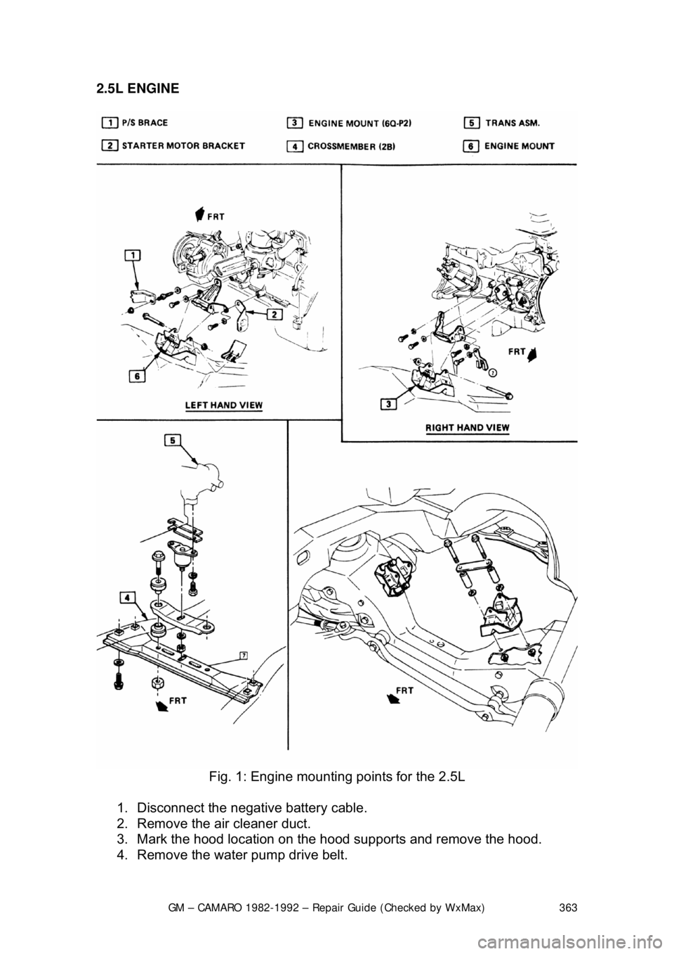
2.5L ENGINE
Fig. 1: Engine mountin g points for the 2.5L
1. Disconnect the negative battery cable.
2. Remove the air cleaner duct.
3. Mark the hood location on the hood supports and remove the hood.
4. Remove the water pump drive belt.
Page 364 of 875

GM – CAMARO 1982-1992 – Repair Guide (Checked by WxMax) 364
5. Drain the radiator and remove t
he radiator hoses. Disconnect the heater
hoses and the transmission cooler lines.
6. Remove the upper half of the radi ator shroud, if equipped with a manual
transmission. Remove the radiator and fan shroud assembly, if equipped
with an automatic transmission.
7. Disconnect the throttle linkage, includi ng the cruise control detent cable.
8. Remove the air conditioning compressor and lay aside.
Do not disconnect the air conditioning lines.
9. Disconnect the power steering pump and drain the fluid into a suitable
container. Remove the vacuum brake booster line.
10. Remove the distributor cap and spark plug wires.
11. Disconnect the engine electrical connection at the bulkhead connection
and disconnect any necessary vacuum hoses.
12. Working inside the vehicle, re move the right-hand hush panel and
disconnect the ECM harness at the EC M. Raise and safely support the
vehicle. Remove the right fenderwell splash shield and feed the harness
through the fenderwell.
13. Disconnect the exhaust pipes at the exhaust manifolds and remove
exhaust system from the vehicle.
14. Remove the flywheel cover and remo ve the converter bolts, if equipped
with automatic transmission.
15. Disconnect the transmission an d starter wire connections.
16. Remove the bellhousing and t he motor mount through-bolts.
17. Disconnect the clutch fork return spring, if equipped with a manual
transmission. Lower the vehicle.
18. Relieve the fuel system pressu re. Disconnect the fuel lines.
19. Support the transmission with a suit able jack. Attach an engine lifting
device.
20. Remove the engine assembly.
To install: 21. Position the engine assembly in the vehicle.
22. Attach the motor mount to engine br ackets and lower the engine in place.
Remove the engine lifting device and the transmission jack.
23. Raise and support the vehicle safely.
24. Install the motor mount through-bolts and tighten the nuts to specification. Install t he bellhousing bolts and tight en to 35 ft. lbs. (47
Nm).
25. On vehicles with automatic transmissi on, install the converter to flywheel
attaching bolts to 46 ft. lbs. (63 Nm).
26. Install the flywheel splash shield and tighten to 89 inch lbs. (10 Nm).
Install the clutch return spring, if equipped with manual transmission.
27. Connect the starter wires and the fuel lines.
28. Install the exhaust system.
29. Lower the vehicle.
30. Install the power steering pump and the air conditioning compressor.
Page 365 of 875
GM – CAMARO 1982-1992 – Repair Guide (Checked by WxMax) 365
31. Connect the bulkhead harness connec
tor, wires and hoses. Reroute the
ECM harness in its original location. Install the hush panel and fenderwell
splash panel.
32. Install the radiator, fan and fan sh roud. Connect the radiator and heater
hoses, along with the transmission cooler lines.
33. Connect the vacuum brake booster li ne, the throttle linkage and cruise
control cable. Install the distributor cap.
34. Fill the cooling system with the proper type and amount of coolant and
the crankcase with the proper type of oil to the correct level.
35. Install the water pump drive bel t, the air cleaner duct and the hood.
36. Connect the negative battery cable, st art the engine and check for leaks.
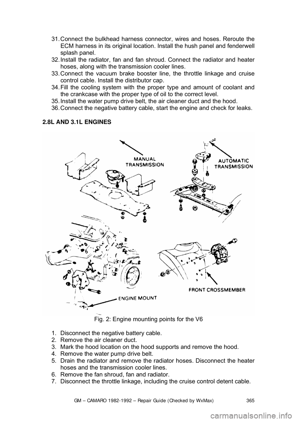
2.8L AND 3.1L ENGINES
Fig. 2: Engine mountin g points for the V6
1. Disconnect the negative battery cable.
2. Remove the air cleaner duct.
3. Mark the hood location on the hood supports and remove the hood.
4. Remove the water pump drive belt.
5. Drain the radiator and remove t he radiator hoses. Disconnect the heater
hoses and the transmission cooler lines.
6. Remove the fan shroud, fan and radiator.
7. Disconnect the throttle linkage, includi ng the cruise control detent cable.
Page 366 of 875

GM – CAMARO 1982-1992 – Repair Guide (Checked by WxMax) 366
8. Remove the air conditioning co
mpressor and lay aside. Remove the
power steering pump and lay aside.
Do not disconnect the air conditioning or power steering lines.
9. Remove the vacuum brake booster line.
10. Remove the distributor cap and spark plug wires.
11. Disconnect the necessary elec trical connections and hoses.
12. Raise and safely support the vehicle.
13. Disconnect the exhaust pipes at the exhaust manifolds.
14. Remove the flywheel cover and remove the converter bolts.
15. Disconnect the star ter wire connections.
16. Remove the bellhousing and t he motor mount through-bolts.
17. Lower the vehicle.
18. Relieve the fuel system pressu re. Disconnect the fuel lines.
19. Support the transmission with a suit able jack. Attach an engine lifting
device.
20. Remove the engine assembly.
To install: 21. Position the engine assembly in the vehicle.
22. Attach the motor mount to engine br ackets and lower the engine in place.
Remove the engine lifting device and the transmission jack.
23. Raise and support the vehicle safely.
24. Install the motor mount through-bolts and tighten the nuts to 50 ft. lbs. (68 Nm). Install the bellhousing bolts and tighten to 35 ft. lbs. (47 Nm).
25. On vehicles with automatic transmissi on, install the converter to flywheel
attaching bolts to 46 ft. lbs. (63 Nm).
26. Install the flywheel splash shield and tighten to 89 inch lbs. (10 Nm).
27. Connect the starter wires and the fuel lines.
28. Install the exhaust pipe on the exhaust manifold.
29. Lower the vehicle.
30. Install the power steering pump and the air conditioning compressor.
31. Connect the necessary wires and hoses.
32. Install the radiator, fan and fan sh roud. Connect the radiator and heater
hoses and the transmission cooler lines.
33. Connect the vacuum brake booster li ne, the throttle linkage and cruise
control cable. Install the distributor cap.
34. Fill the cooling system with the proper type and amount of coolant and
the crankcase with the proper type of oil to the correct level.
35. Install the water pump drive bel t, the air cleaner duct and the hood.
36. Connect the negative battery cable, st art the engine and check for leaks.
Page 367 of 875
GM – CAMARO 1982-1992 – Repair Guide (Checked by WxMax) 367
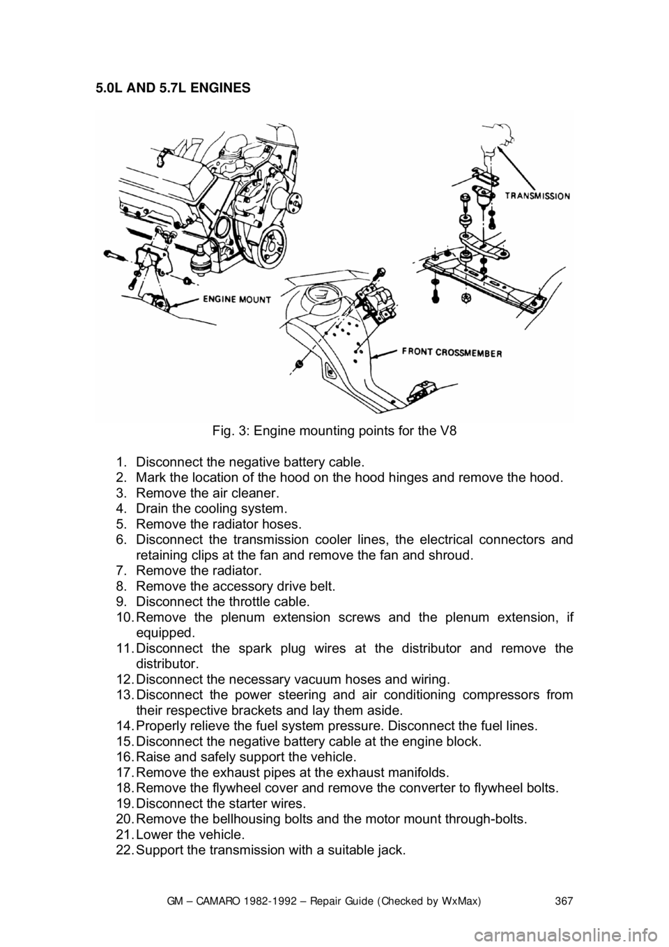
5.0L AND 5.7L ENGINES
Fig. 3: Engine mountin g points for the V8
1. Disconnect the negative battery cable.
2. Mark the location of the hood on the hood hinges and remove the hood.
3. Remove the air cleaner.
4. Drain the cooling system.
5. Remove the radiator hoses.
6. Disconnect the transmission cooler li nes, the electrical connectors and
retaining clips at the fan and remove the fan and shroud.
7. Remove the radiator.
8. Remove the accessory drive belt.
9. Disconnect the throttle cable.
10. Remove the plenum extension scr ews and the plenum extension, if
equipped.
11. Disconnect the spark plug wires at the distributor and remove the
distributor.
12. Disconnect the necessary vacuum hoses and wiring.
13. Disconnect the power steering and air conditioning compressors from
their respective brackets and lay them aside.
14. Properly relieve the fuel system pressure. Disconnect the fuel lines.
15. Disconnect the negative battery cable at the engine block.
16. Raise and safely support the vehicle.
17. Remove the exhaust pipes at the exhaust manifolds.
18. Remove the flywheel cover and remove the converter to flywheel bolts.
19. Disconnect the starter wires.
20. Remove the bellhousing bolts and the motor mount through-bolts.
21. Lower the vehicle.
22. Support the transmission with a suitable jack.
Page 368 of 875

GM – CAMARO 1982-1992 – Repair Guide (Checked by WxMax) 368
23. Remove the AIR/converter bracket
and ground wires from the rear of the
cylinder head.
24. Attach a suitable lifting devic e and remove the engine assembly.
To install: 25. Position the engine assembly in the vehicle.
26. Attach the motor mount to engine brackets and lower the engine into
place.
27. Remove the engine lifting device and the transmission jack.
28. Raise and safely support the vehicle.
29. Install the motor mount through-bolts and tighten to 50 ft. lbs. (68 (Nm).
30. Install the bellhousing bolts and tighten to 35 ft. lbs. (47 Nm).
31. On vehicles with automatic transmissi on, install the converter to flywheel
bolts. Tighten the bolts to 46 ft. lbs. ( 63 Nm). Install the flywheel cover.
32. Connect the starter wires and the fuel lines.
33. Connect the exhaust pipe at the exhaust manifold.
34. Lower the vehicle.
35. Connect the necessary wires and hoses.
36. Install the power steering pump and air conditioning compressor in their
respective brackets.
37. Install the radiator, fan and fan sh roud, radiator hoses and heater hoses.
38. Connect the transmission cooler lines and cooling fan electrical
connectors.
39. Install the distributor.
40. Install the plenum ex tension, if equipped.
41. Fill the cooling system with the proper type and quantity of coolant and
the crankcase with the proper type of oil to the correct level.
42. Install the air cleaner and the hood.
43. Connect the negative battery cable, start the engine, check for leaks and
check timing.
Page 369 of 875
GM – CAMARO 1982-1992 – Repair Guide (Checked by WxMax) 369
ROCKER ARM COVER
REMOVAL & INSTALLATION
2.5L ENGINE
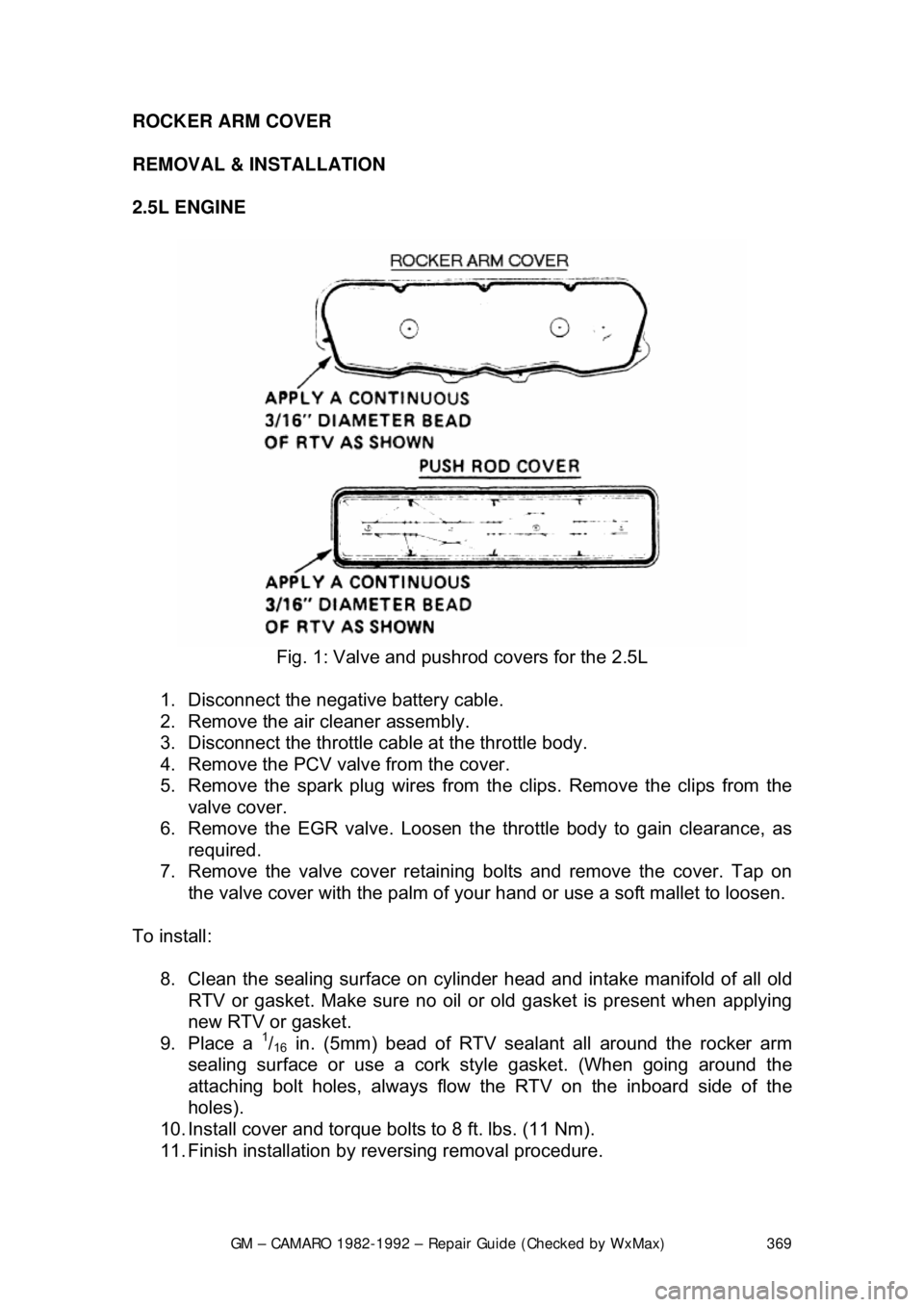
Fig. 1: Valve and pushrod covers for the 2.5L
1. Disconnect the negative battery cable.
2. Remove the air cleaner assembly.
3. Disconnect the throttle c able at the throttle body.
4. Remove the PCV valve from the cover.
5. Remove the spark plug wires from t he clips. Remove the clips from the
valve cover.
6. Remove the EGR valve. Loosen t he throttle body to gain clearance, as
required.
7. Remove the valve cover retaining bolts and remove the cover. Tap on
the valve cover with the palm of your hand or use a soft mallet to loosen.
To install: 8. Clean the sealing surface on cylinder head and intake manifold of all old
RTV or gasket. Make sure no oil or ol d gasket is present when applying
new RTV or gasket.
9. Place a
1/16 in. (5mm) bead of RTV sealan t all around the rocker arm
sealing surface or use a cork style gasket. (When going around the
attaching bolt holes, always flow t he RTV on the inboard side of the
holes).
10. Install cover and torque bolts to 8 ft. lbs. (11 Nm).
11. Finish installation by reversing removal procedure.
Page 370 of 875
GM – CAMARO 1982-1992 – Repair Guide (Checked by WxMax) 370
2.8L AND 3.1L ENGINES
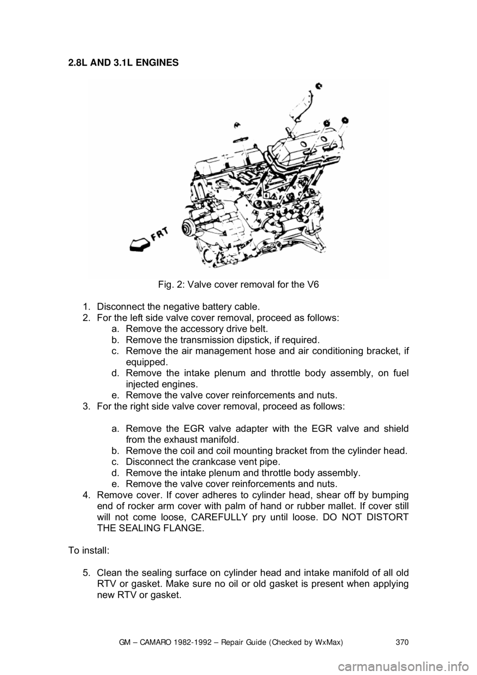
Fig. 2: Valve cover removal for the V6
1. Disconnect the negative battery cable.
2. For the left side valve cove r removal, proceed as follows:
a. Remove the accessory drive belt.
b. Remove the transmission dipstick, if required.
c. Remove the air management hose and air conditioning bracket, if
equipped.
d. Remove the intake plenum and throttle body assembly, on fuel
injected engines.
e. Remove the valve cover reinforcements and nuts.
3. For the right side valve cover removal, proceed as follows:
a. Remove the EGR valve adapter with the EGR valve and shield
from the exhaust manifold.
b. Remove the coil and coil mounting bracket from the cylinder head.
c. Disconnect the crankcase vent pipe.
d. Remove the intake plenum and throttle body assembly.
e. Remove the valve cover reinforcements and nuts.
4. Remove cover. If cover adheres to cylinder head, shear off by bumping end of rocker arm cover with palm of hand or rubber mallet. If cover still
will not come loose, CAREFULLY pry until loose. DO NOT DISTORT
THE SEALING FLANGE.
To install: 5. Clean the sealing surface on cylinder head and intake manifold of all old
RTV or gasket. Make sure no oil or ol d gasket is present when applying
new RTV or gasket.