CHEVROLET CAMARO 1982 Repair Guide
Manufacturer: CHEVROLET, Model Year: 1982, Model line: CAMARO, Model: CHEVROLET CAMARO 1982Pages: 875, PDF Size: 88.64 MB
Page 311 of 875
GM – CAMARO 1982-1992 – Repair Guide (Checked by WxMax) 311
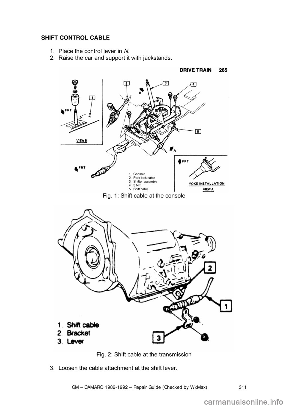
SHIFT CONTROL CABLE
1. Place the control lever in N.
2. Raise the car and support it with jackstands.
Fig. 1: Shift cable at the console
Fig. 2: Shift cable at the transmission
3. Loosen the cable attachment at the shift lever.
Page 312 of 875
GM – CAMARO 1982-1992 – Repair Guide (Checked by WxMax) 312
4. Rotate the shift lever clockwis
e to the park detent and then back to
neutral.
5. Tighten cable attachment to 11 ft. lbs. (15 Nm).
The lever must be held out of P when tightening the nut.
SHIFT LINKAGE 1. Place the manual shaft of the transmission in N. Place the console shift
lever in N.
2. Install the cable in the slot of the shift lever. Adjust the cable so that the
pin has free movement.
3. Install and tighten t he nut to the pin.
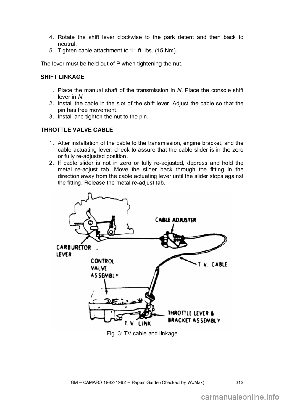
THROTTLE VALVE CABLE 1. After installation of the cable to the transmission, engine bracket, and the
cable actuating lever, check to assure that the cable slider is in the zero
or fully re-adjusted position.
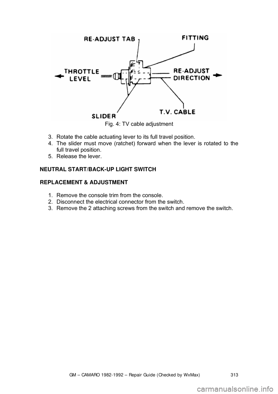
2. If cable slider is not in zero or fully re-adjusted, depress and hold the
metal re-adjust tab. Move the sli der back through the fitting in the
direction away from the cable actuat ing lever until the slider stops against
the fitting. Release the metal re-adjust tab.
Fig. 3: TV cable and linkage
Page 313 of 875
GM – CAMARO 1982-1992 – Repair Guide (Checked by WxMax) 313
Fig. 4: TV cable adjustment
3. Rotate the cable actuating leve r to its full travel position.
4. The slider must move (ratchet) forw ard when the lever is rotated to the
full travel position.
5. Release the lever.
NEUTRAL START/BACK-UP LIGHT SWITCH
REPLACEMENT & ADJUSTMENT 1. Remove the console tr im from the console.
2. Disconnect the electrical connector from the switch.
3. Remove the 2 attaching screws from the switch and remove the switch.
Page 314 of 875
GM – CAMARO 1982-1992 – Repair Guide (Checked by WxMax) 314
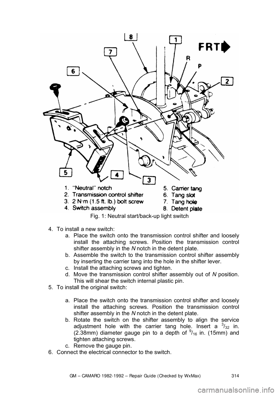
Fig. 1: Neutral start/back-up light switch
4. To install a new switch: a. Place the switch onto the trans mission control shifter and loosely
install the attaching screws. Po sition the transmission control
shifter assembly in the N notch in the detent plate.
b. Assemble the switch to the tr ansmission control shifter assembly
by inserting the carrier tang into the hole in the shifter lever.
c. Install the attaching screws and tighten.
d. Move the transmission control shifter assembly out of N position.
This will shear the switch internal plastic pin.
5. To install the original switch:
a. Place the switch onto the trans mission control shifter and loosely
install the attaching screws. Po sition the transmission control
shifter assembly in the N notch in the detent plate.
b. Rotate the switch on the shifter assembly to align the service adjustment hole with the carrier tang hole. Insert a
3/32 in.
(2.38mm) diameter g auge pin to a depth of 9/16 in. (15mm) and
tighten attaching screws.
c. Remove the gauge pin.
6. Connect the electrical connector to the switch.
Page 315 of 875
GM – CAMARO 1982-1992 – Repair Guide (Checked by WxMax) 315
7. Install the console tr
im to the console.
PARK LOCK CABLE
REMOVAL & INSTALLATION
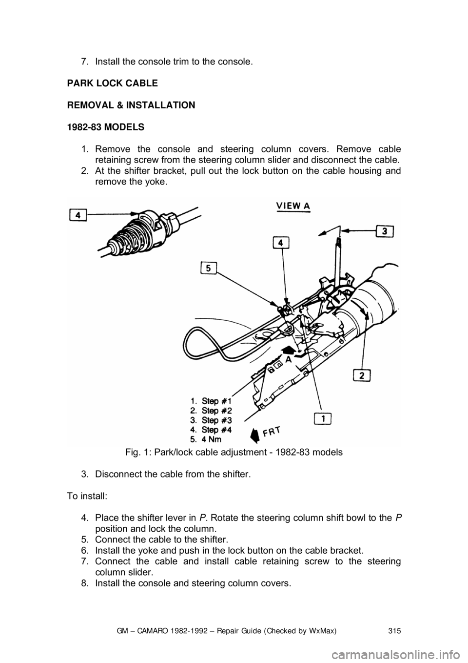
1982-83 MODELS 1. Remove the console and steering column covers. Remove cable retaining screw from the steering colu mn slider and disconnect the cable.
2. At the shifter bracket, pull out t he lock button on the cable housing and
remove the yoke.
Fig. 1: Park/lock cable adjustment - 1982-83 models
3. Disconnect the cable from the shifter.
To install: 4. Place the shifter lever in P. Rotate the steering column shift bowl to the P
position and lock the column.
5. Connect the cable to the shifter.
6. Install the yoke and push in t he lock button on the cable bracket.
7. Connect the cable and install cabl e retaining screw to the steering
column slider.
8. Install the console and steering column covers.
Page 316 of 875
GM – CAMARO 1982-1992 – Repair Guide (Checked by WxMax) 316
1984-89 MODELS
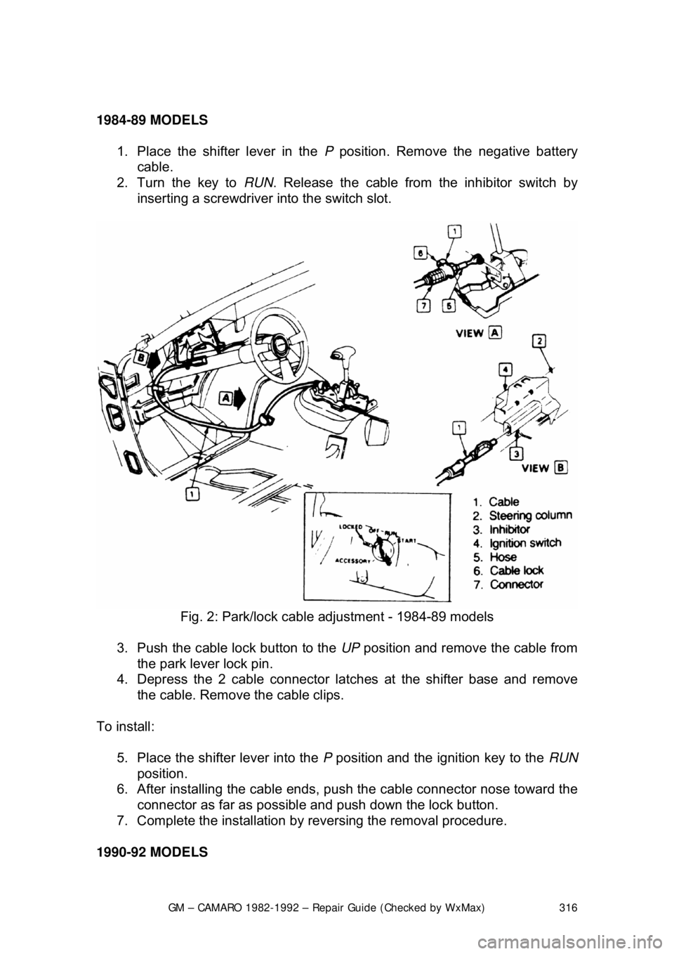
1. Place the shifter lever in the P position. Remove the negative battery
cable.
2. Turn the key to RUN. Release the cable from the inhibitor switch by
inserting a screwdriver into the switch slot.
Fig. 2: Park/lock cable adjustment - 1984-89 models
3. Push the cable lock button to the UP position and remove the cable from
the park lever lock pin.
4. Depress the 2 cable connector latc hes at the shifter base and remove
the cable. Remove the cable clips.
To install: 5. Place the shifter lever into the P position and the ignition key to the RUN
position.
6. After installing the cable ends, push the cable connector nose toward th\
e connector as far as possible and push down the lock button.
7. Complete the installation by reversing the removal procedure.
1990-92 MODELS
Page 317 of 875

GM – CAMARO 1982-1992 – Repair Guide (Checked by WxMax) 317
1. Place the shifter lever in the
P position. Remove the negative battery
cable.
2. Turn the key to RUN.
3. Remove the left side instrument panel sound insulator and kick panels.
4. Remove the floor console.
5. Remove the cable nut and clip. Remove the cable from the bracket, move the button to the UP position and unsnap the cable end from the
lever lock pin.
6. Lower the steering column. Remove the cable clips.
To install: 7. Place the shifter lever into the P position and the ignition key to the RUN
position.
8. After installing the cable ends, push the cable connector nose toward th\
e connector as far as possible and push down the lock button.
9. Complete the installation by reversing the removal procedure.
EXTENSION HOUSING SEAL (IN VEHICLE)
REMOVAL & INSTALLATION
This seal controls transmission oil leakage around the driveshaft. Continued
failure of this seal usually indicates a worn output shaft bushing. If so, there will
be signs of the same wear on the driveshaft where it contacts the seal and
bushing. The seal is available and is fairly simple to install, with the proper tool.
1. Raise and safely support rear of t he vehicle to minimize transmission oil
loss when the driveshaft is removed.
2. Unbolt the driveshaft fr om the differential and center support bearing, if
equipped. Wrap tape around the bearing cu ps to keep them in place on
the universal joint and slide the sh aft out of the transmission.
3. Use a small pry tool to carefully pr y out the old seal. Be careful not to
insert the tool too far into the hous ing or the bushing will be damaged.
4. Use an oil seal installation tool to evenly drive the new seal into the
housing. Make sure the tool only cont acts the outer metal portion of the
seal.
5. Install the driveshaft. Torque the uni versal bearing cup retainer bolts to
15 ft. lbs. (20 Nm). Recheck fluid level.
TRANSMISSION
REMOVAL & INSTALLATION 1. Disconnect the negative batte ry cable at the battery.
2. Remove the air cleaner assembly.
3. Disconnect the throttle valve (TV) control cable at the carburetor.
Page 318 of 875
GM – CAMARO 1982-1992 – Repair Guide (Checked by WxMax) 318
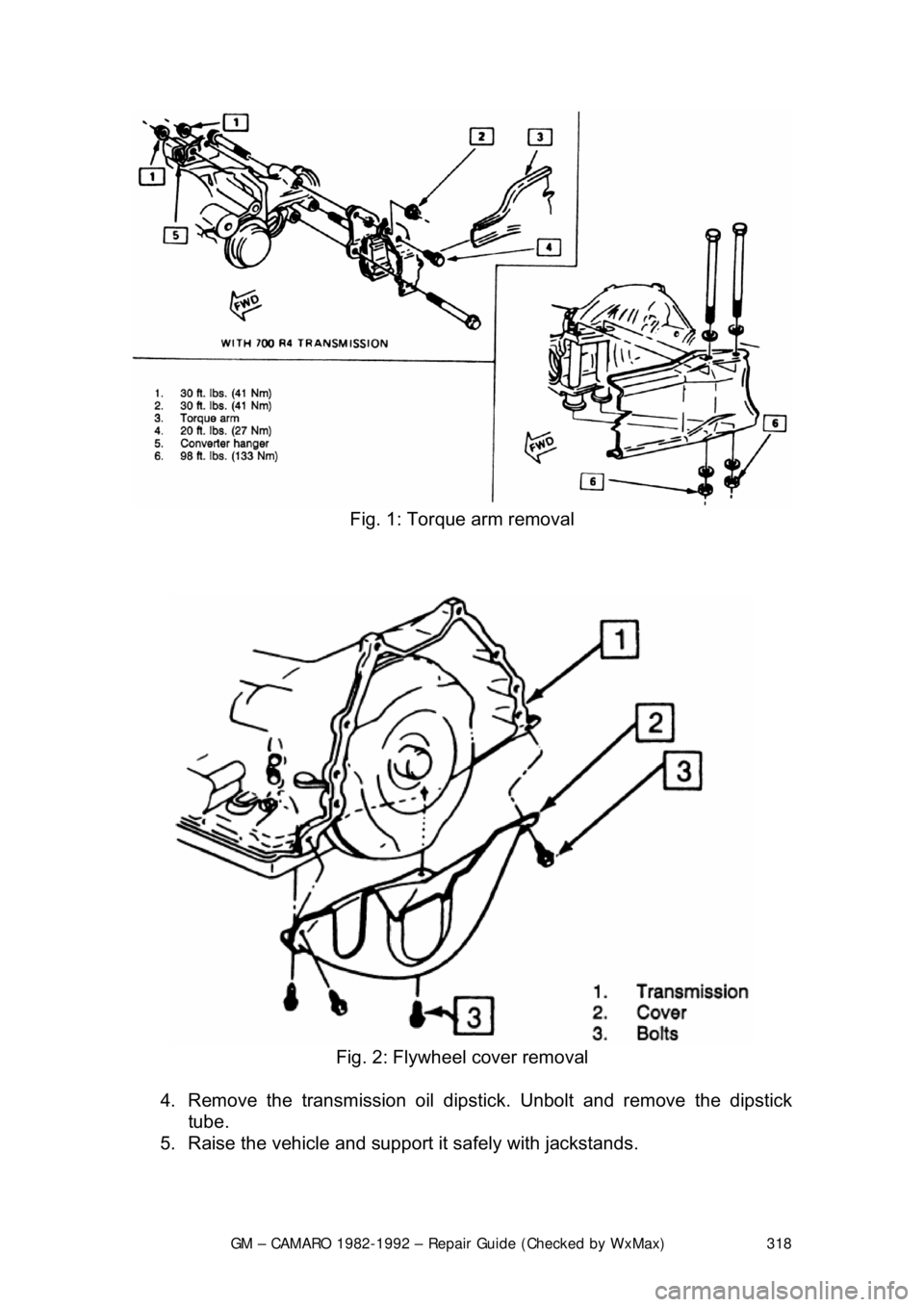
Fig. 1: Torque arm removal
Fig. 2: Flywheel cover removal
4. Remove the transmission oil dipsti ck. Unbolt and remove the dipstick
tube.
5. Raise the vehicle and support it safely with jackstands.
Page 319 of 875
GM – CAMARO 1982-1992 – Repair Guide (Checked by WxMax) 319
In order to provide adequat
e clearance for transmission removal, it may be
necessary to raise both the front and the rear of the vehicle.
6. Mark the relationship between the driveshaft and the rear pinion flange
so that the driveshaft may be reinst alled in its original position.
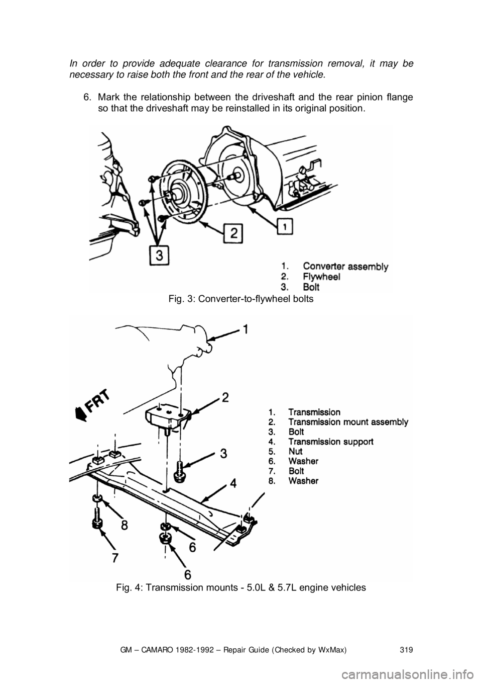
Fig. 3: Converter-to-flywheel bolts
Fig. 4: Transmission mounts - 5.0L & 5.7L engine vehicles
Page 320 of 875
GM – CAMARO 1982-1992 – Repair Guide (Checked by WxMax) 320
7. Unbolt the universal joint straps fr
om the pinion flange (use care to keep
the universal joint caps in place), lower and remove the driveshaft from
the vehicle. Place a transmission tailshaft plug or rag in place of the \
driveshaft to keep the transmission fluid from draining out.
8. Disconnect the catalytic converter support bracket at the transmission.
9. Disconnect the speedometer cable, electrical connectors and the shift
control cable from the transmission.
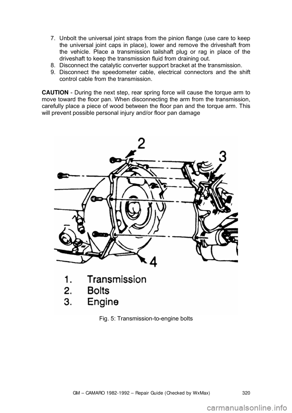
CAUTION - During the next step, rear spring force will cause the torque arm to
move toward the floor pan. When disconn ecting the arm from the transmission,
carefully place a piece of wood between the floor pan and the torque arm. This
will prevent possible personal injury and/or floor pan damage
Fig. 5: Transmission-to-engine bolts