CHEVROLET CAMARO 1982 Repair Guide
Manufacturer: CHEVROLET, Model Year: 1982, Model line: CAMARO, Model: CHEVROLET CAMARO 1982Pages: 875, PDF Size: 88.64 MB
Page 341 of 875
GM – CAMARO 1982-1992 – Repair Guide (Checked by WxMax) 341
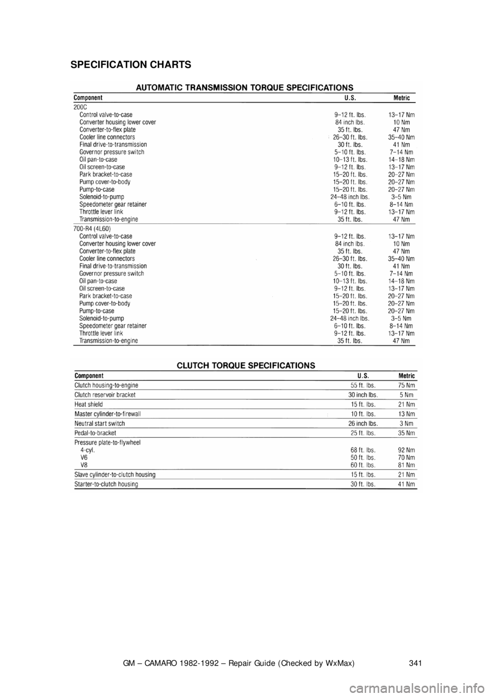
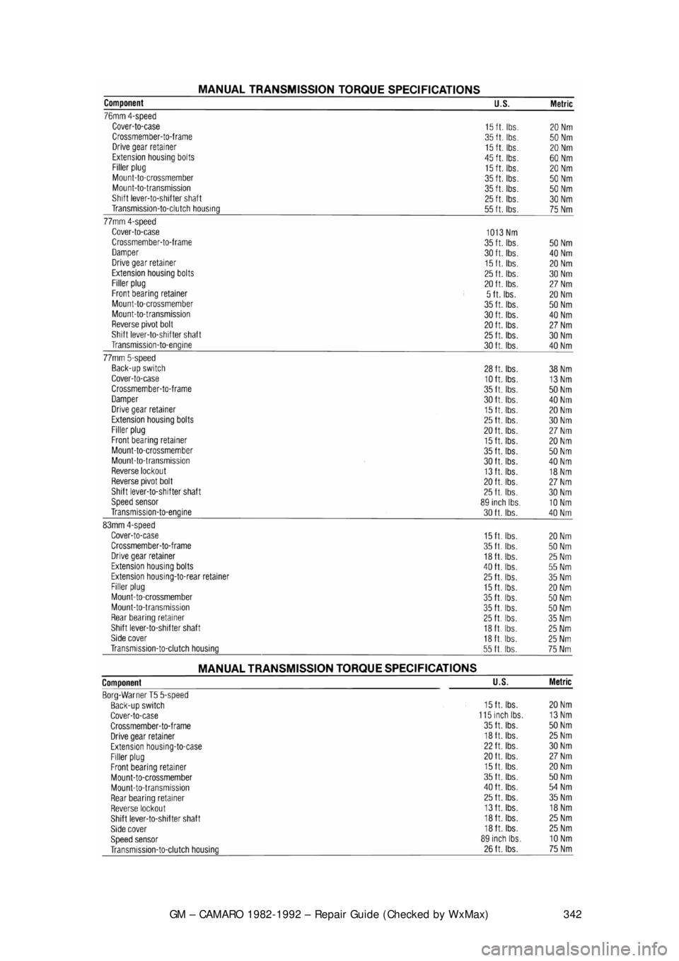
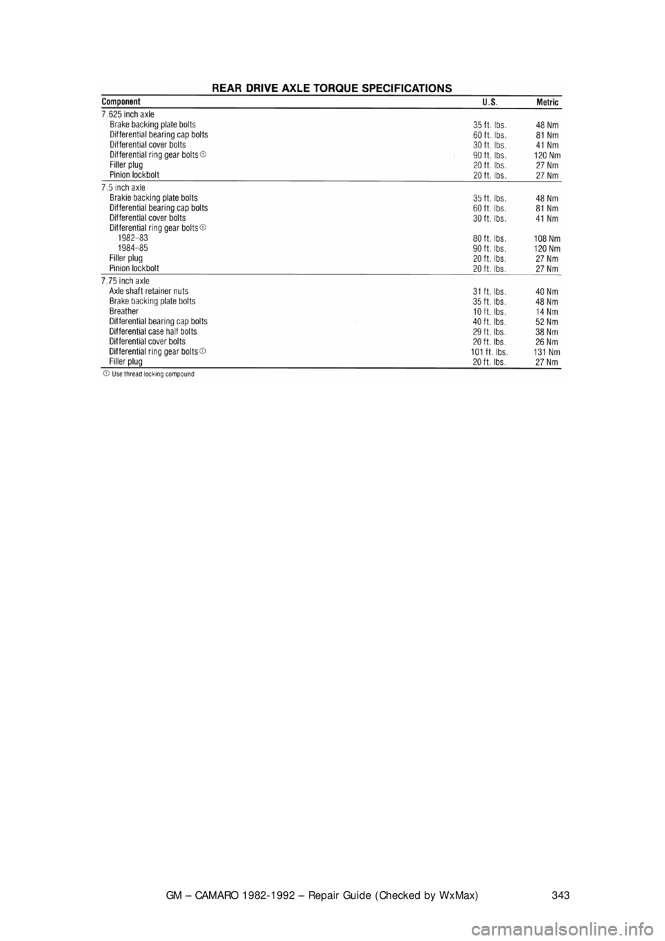
SPECIFICATION CHARTS
Page 342 of 875
GM – CAMARO 1982-1992 – Repair Guide (Checked by WxMax) 342
Page 343 of 875
GM – CAMARO 1982-1992 – Repair Guide (Checked by WxMax) 343
Page 344 of 875

GM – CAMARO 1982-1992 – Repair Guide (Checked by WxMax) 344
ENGINE & ENGINE OVERHAUL
ENGINE ELECTRICAL
ENGINE ELECTRICAL
The engine electrical system can be brok en down into three inter-related, but
distinct systems:
1. The starting system.
2. The charging system.
3. The ignition system.
BATTERY AND STARTING SYSTEM
The battery is the first link in the chai n of mechanisms which work together to
provide cranking of the autom obile engine. In most modern cars, the battery is a
lead-acid electrochemical device consis ting of six two-volt (2V) subsections
connected in series so the unit is c apable of producing approximately 12V of
electrical pressure. Each subsection, or ce ll, consists of a series of positive and
negative plates held a short distance apart in a solution of sulfuric acid and
water. The two types of plates are of di ssimilar metals. This causes a chemical
reaction to be set up, and it is this reacti on which produces current flow from the
battery when its positive and negative te rminals are connected to an electrical
appliance such as a lamp or motor.
The continued transfer of electrons would ev entually convert the sulfuric acid in
the electrolyte to water and make t he two plates identical in chemical
composition. As electrical energy is removed from the battery, its voltage output
tends to drop. Thus, measuring batte ry voltage and battery electrolyte
composition are two ways of checking the ability of the unit to supply power.
During the starting of the eng ine, electrical energy is removed from the battery.
However, if the charging circuit is in good condition and the operating conditions
are normal, the power removed from the battery will be replaced by the
generator (or alternator) which will forc e electrons back through the battery,
reversing the normal flow, and restoring the ba ttery to its original chemical state.
The battery and starting motor are linked by very heavy electrical cable\
s
designed to minimize resistance to the flow of current. Generally, the major
power supply cable that leaves the batte ry goes directly to the starter, while
other electrical system needs are supplied by a smaller cable. During the starter
operation, power flows from the battery to the starter and is grounded through
the car's frame and the batte ry's negative ground strap.
The starting motor is a specially designed, direct current electric motor capable
of producing a very great am ount of power for its size. One thing that allows the
motor to produce a great deal of power is its tremendous rotating speed. It
drives the engine through a ti ny pinion gear (attached to the starter's armature),
which drives the very large flywheel ring gear at a greatly reduced speed.
Another factor allowing it to produce so much power is that only intermittent
Page 345 of 875

GM – CAMARO 1982-1992 – Repair Guide (Checked by WxMax) 345
operation is required of it. Thus, little a
llowance for air circulation is required,
and the windings can be built into a very small space.
The starter solenoid is a magnetic dev ice which employs the small current
supplied by the starting switch circuit of the ignition switch. This magnetic action
moves a plunger which mechanically engages the starter and electrically closes
the heavy switch which connects it to t he battery. The starting switch circuit
consists of the starting switch cont ained within the ignition switch, a
transmission neutral safety switch or clutch pedal switch, and the wiring
necessary to connect these with the starter solenoid or relay.
A pinion, which is a small gear, is m ounted to a one-way drive clutch. This
clutch is splined to the starter armature shaft. When the ignition switch is moved
to the start position, the solenoid plunger slides the pinion toward the flywheel
ring gear via a collar and spring. If t he teeth on the pinion and flywheel match
properly, the pinion will engage the flywheel immediately. If the gear teeth butt
one another, the spring will be compressed and will force the gears to mesh as
soon as the starter turns far enough to a llow them to do so. As the solenoid
plunger reaches the end of it s travel, it closes the contacts that connect the
battery and starter and then the engine is cranked.
As soon as the engine star ts, the flywheel ring gear begins turning fast enough
to drive the pinion at an ex tremely high rate of speed. At this point, the one-way
clutch begins allowing the pi nion to spin faster than the starter shaft so that the
starter will not operate at excessive speed. When the i gnition switch is released
from the starter position, the solenoid is de-energized, and a spring contained
within the solenoid assembly pulls the gear out of mesh and interrupts the
current flow to the starter.
Some starters employ a separate relay, mounted away from the starter, to
switch the motor and solenoid current on and off. The relay thus replaces the
solenoid electrical switch, but does not eliminate the need for a solenoid
mounted on the starter used to mechanica lly engage the starter drive gears.
The relay is used to reduce the amount of current the starting switch must carry.
THE CHARGING SYSTEM
The automobile charging system provides electrical power for operation of the
vehicle's ignition and star ting systems and all the electrical accessories. The
battery serves as an electrical surge or storage tank, storing (in chemical form)
the energy originally pr oduced by the engine driven gen erator. The system also
provides a means of regulating alternat or output to protect the battery from
being overcharged and to avoid excess ive voltage to the accessories.
The storage battery is a chemical device in corporating parallel lead plates in a
tank containing a sulfuric acid-water solution. Adjacent plates are slightly
dissimilar, and the chemical reaction of the two dissimilar plates produces
electrical energy when the battery is connected to a load such as the starter
motor. The chemical reaction is reversible, so that when the generator i\
s
producing a voltage (electrical pressure ) greater than that produced by the
Page 346 of 875

GM – CAMARO 1982-1992 – Repair Guide (Checked by WxMax) 346
battery, electricity is forced into the battery
, and the battery is returned to its fully
charged state.
Alternators are used on the modern autom obiles for they are lighter, more
efficient, can rotate at higher speeds and have fewer brush problems. In an
alternator, the field rotates while al l the current produced passes only through
the stators windings. The brushes bear agains t continuous slip rings rather than
a commutator. This causes the current produced to periodically reverse the
direction of its flow. Diodes (electrica l one-way switches) block the flow of
current from traveling in t he wrong direction. A series of diodes is wired together
to permit the alternating flow of the st ator to be converted to a pulsating, but
unidirectional flow at the alternator out put. The alternator's field is wired in
series with the voltage regulator.
Please refer to Engine Performance & Tune-up for ignition system testing
procedures.
IGNITION COIL
REMOVAL & INSTALLATION
INTERNALLY MOUNTED COIL 1. Disconnect and label the wires from cap.
2. Remove the distributor cap from the distributor.
3. On the distributor cap, remove t he coil cover attaching screws and the
cover.
4. Remove the ignition coil attaching screws and lift the coil from the cap.
To install: 5. Position the coil and secure it with the attaching screws. Be sure to install
the carbon button and rubber disc first.
6. Install the coil cover and attaching screws.
7. Install the distributor cap.
8. Connect the wires to the cap.
EXTERNALLY MOUNTED COIL 1. Label and disconnect the wires from the coil.
2. Remove the ignition coil mounting bolts and the coil.
To install: 3. To install, position the coil into place and se cure it with the mounting
bolts.
4. Connect the wires to the coil.
IGNITION MODULE
Page 347 of 875
GM – CAMARO 1982-1992 – Repair Guide (Checked by WxMax) 347
REMOVAL & INSTALLATION
1. Disconnect the wires from the cap.
2. Remove the distributor cap.
3. Remove the two module attaching screws and capacitor attaching screw.
Lift module, capacitor and harnes s assembly from base.
4. Disconnect wiring harness.
To install: 5. Apply silicone grease underneath the module. This grease is necessary
for ignition module cooling.
6. Connect the wiring harness.
7. Install the module and attaching screws.
8. Install the distributor cap and wires.
DISTRIBUTOR
REMOVAL & INSTALLATION
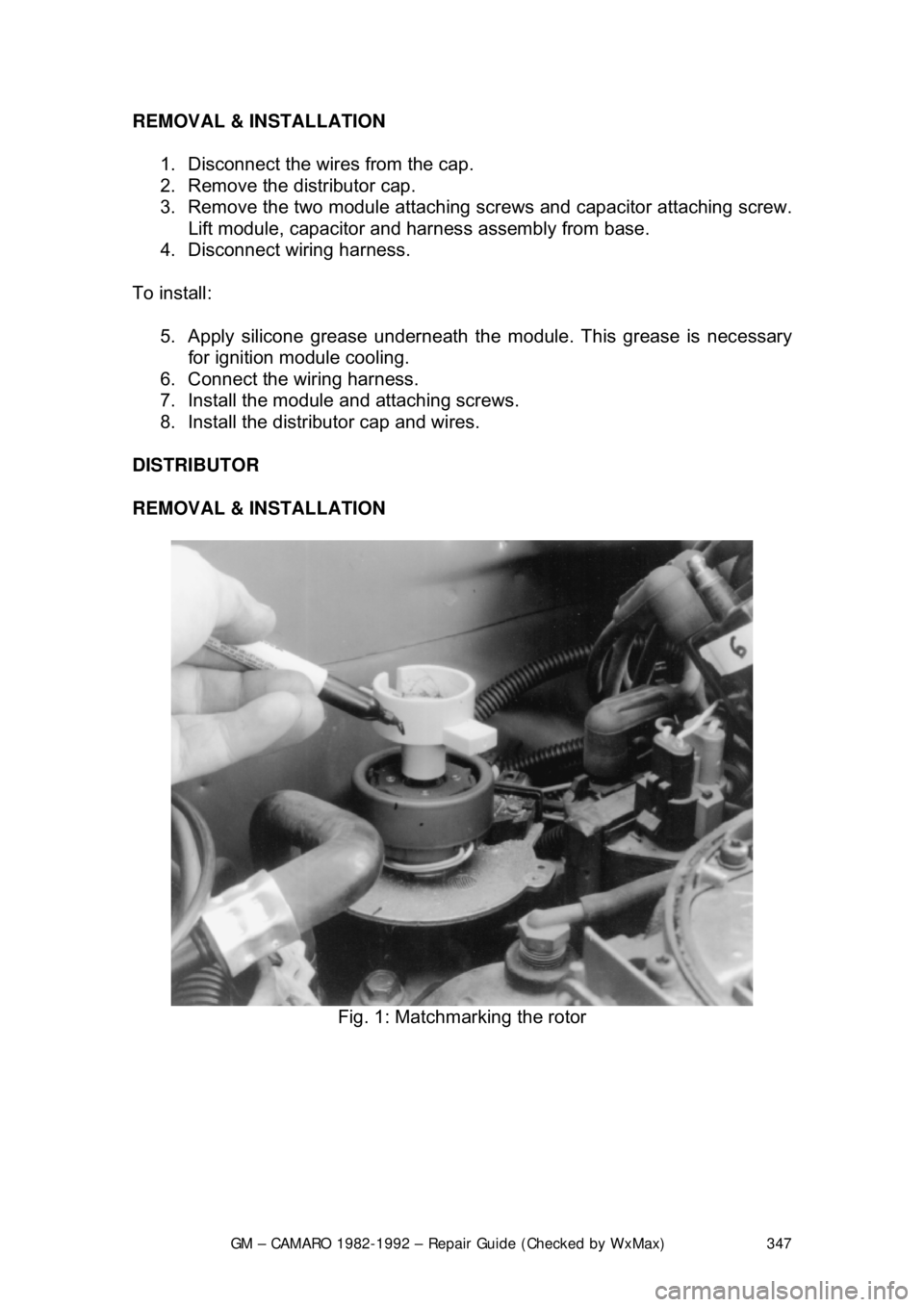
Fig. 1: Matchmarking the rotor
Page 348 of 875
GM – CAMARO 1982-1992 – Repair Guide (Checked by WxMax) 348
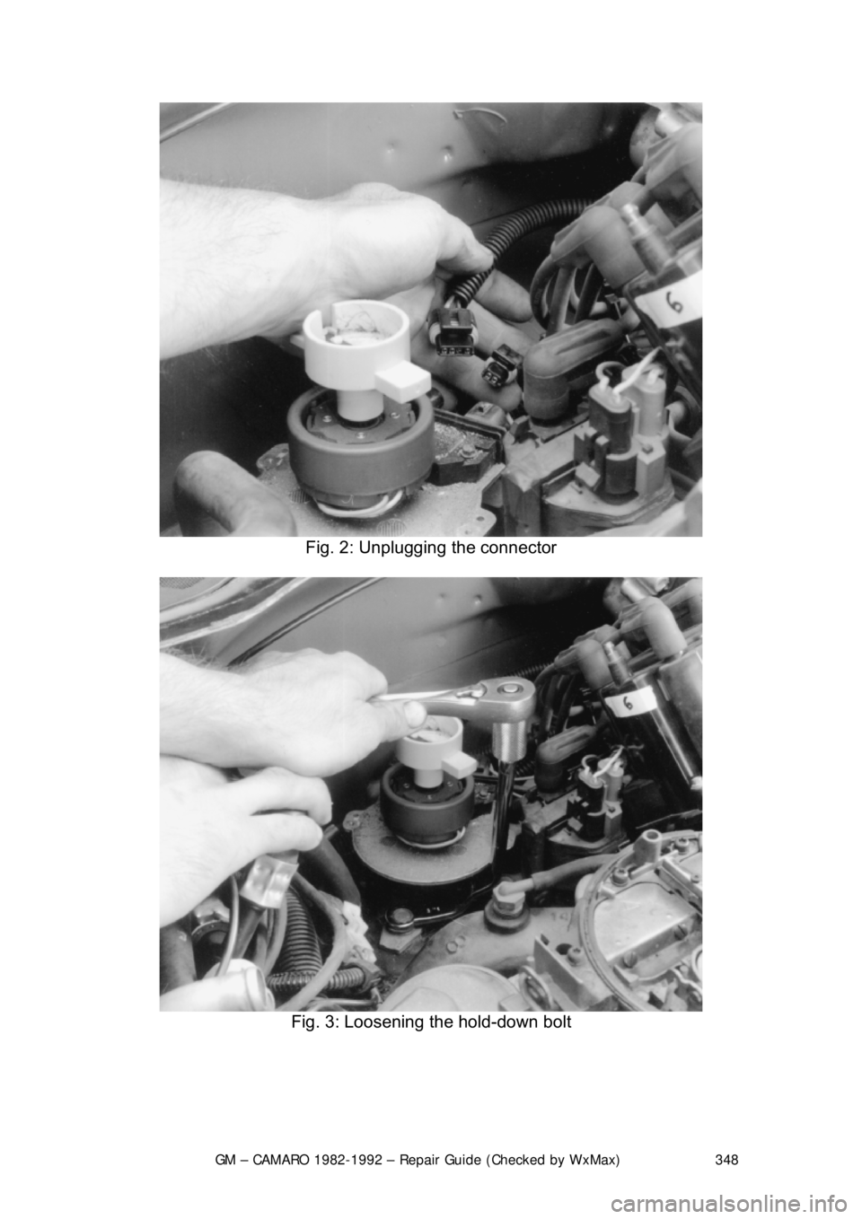
Fig. 2: Unplugging the connector
Fig. 3: Loosening the hold-down bolt
Page 349 of 875
GM – CAMARO 1982-1992 – Repair Guide (Checked by WxMax) 349
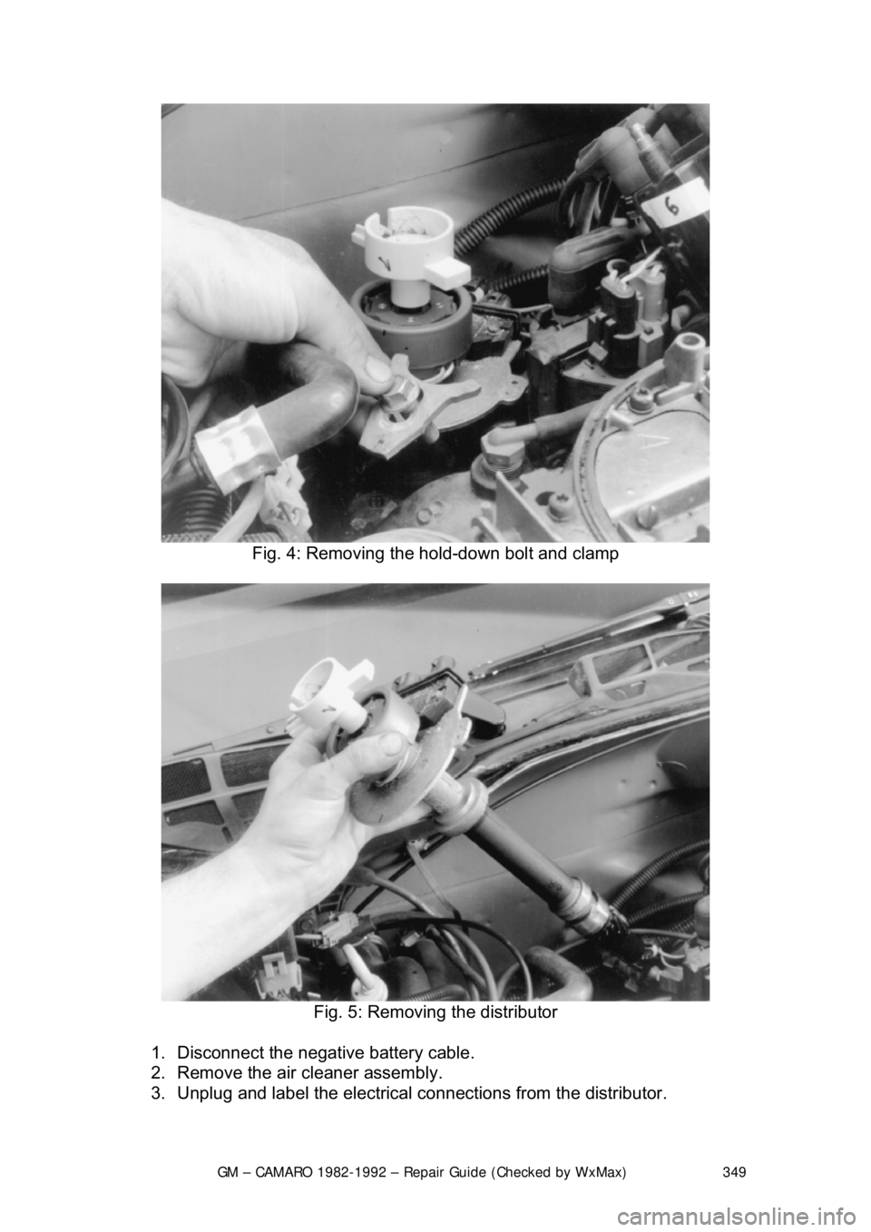
Fig. 4: Removing the hold-down bolt and clamp
Fig. 5: Removing the distributor
1. Disconnect the negative battery cable.
2. Remove the air cleaner assembly.
3. Unplug and label the electrical connections from the distributor.
Page 350 of 875

GM – CAMARO 1982-1992 – Repair Guide (Checked by WxMax) 350
4. Remove the distributor cover and wi
re retainer, if equipped. Turn the
retaining screws counterclockwise and remove the cap.
5. Mark the relationship of the roto r to the distributor housing and the
housing relationship to the engine.
6. Remove the distributor reta ining bolt and hold-down clamp.
7. Pull the distri butor up until the rotor just stops turning counterclockwise
and again note the position of the rotor.
8. Remove the distribut or from the engine.
To install: 9. Insert the distributor into the engine, with the rotor aligned to the last
mark made, then slowly install the dist ributor the rest of the way until all
marks previously made are aligned.
10. Install the distributor hold- down clamp and retaining bolt.
11. If removed, install the wiring harness retainer and secondary wires.
12. Install the distributor cap.
13. Engage the wire connections on t he distributor. Make certain the
connectors are fully seated and latched.
14. Reconnect the negative battery cable.
If the engine was accidentally cranked afte r the distributor was removed, the
following procedure can be used during installation.
15. Remove the No. 1 spark plug.
16. Place a finger over the spark pl ug hole. Have a helper turn the engine
slowly using a wrench on the crankshaft bolt until compression is felt. \
17. Align the timing mark on the pulley to 0 on the engine timing indicator.
18. Turn the rotor to point to the No . 1 spark plug tower on the distributor
cap.
19. Install the distributor assembly in the engine and ensure the rotor is
pointing toward the No. 1 spark plug tower.
20. Install the cap and spark plug wires.
21. Check and adjust engine timing.
ALTERNATOR
DESCRIPTION
An alternator differs from a DC shunt generator in that the armature is
stationary, and is called the stator, while the field rotates and is called the rotor.
The higher current values in the alternator's stator are conducted to the external
circuit through fixed leads and connecti ons, rather than through a rotating
commutator and brushes as in a DC generator. This eliminates a major point of
maintenance.
The rotor assembly is supported in the drive end frame by a ball bearing and at
the other end by a roller bearing. These bearings are lubricated during
assembly and require no main tenance. There are six diodes in the end frame
assembly. These diodes are electrical check valves that also change the