CHEVROLET CAMARO 1982 Repair Guide
Manufacturer: CHEVROLET, Model Year: 1982, Model line: CAMARO, Model: CHEVROLET CAMARO 1982Pages: 875, PDF Size: 88.64 MB
Page 291 of 875

GM – CAMARO 1982-1992 – Repair Guide (Checked by WxMax) 291
6. Remove the console cover.
7. Remove the shifter boot.
8. Remove the shifter mounting bolt
s and remove the shifter assembly.
9. Installation is the reverse of the removal procedure. Adjust the linkage as
detailed earlier.
BACK-UP LIGHT SWITCH
REMOVAL & INSTALLATION 1. Disconnect the negative battery terminal from the battery.
2. At the left-rear of the transmission, the back-up light switch is threaded
into the transmission case. The speed sensor is held in with a separate
bracket. Disconnect the electrical co nnector from the back-up light
switch.
3. Remove the back-up light swit ch from the transmission.
4. To install, reverse the remova l procedures. Coat the threads with
Teflon® tape. Please refer to the to rque chart for specifications. Place
the gear shift lever in the revers e position and check that the back-up
lights work.
EXTENSION HOUSING SEAL
REMOVAL & INSTALLATION
This seal controls transmission oil leakage around the driveshaft. Continued
failure of this seal usually indicates a worn output shaft bushing. If so, there will
be signs of the same wear on the driveshaft where it contacts the seal and
bushing. The seal is available and is fairly simple to install, with the proper tool.
1. Raise and safely support the rear of the vehicle to minimize transmission
oil loss when the driveshaft is removed.
2. Unbolt the driveshaft fr om the differential and center support bearing, if
equipped. Wrap tape around the bearing cu ps to keep them in place on
the universal joint and slide the sh aft out of the transmission.
3. Use an small pry tool to carefully pry out the old seal. Be careful not to
insert the tool too far into the hous ing or the bushing will be damaged.
Page 292 of 875
GM – CAMARO 1982-1992 – Repair Guide (Checked by WxMax) 292
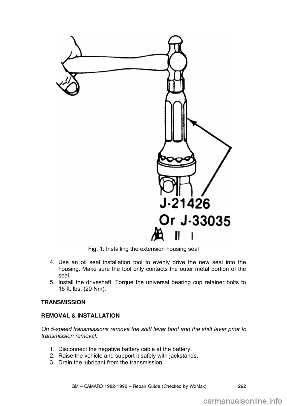
Fig. 1: Installing the extension housing seal
4. Use an oil seal installation tool to evenly drive the new seal into the
housing. Make sure the tool only cont acts the outer metal portion of the
seal.
5. Install the driveshaft. Torque the uni versal bearing cup retainer bolts to
15 ft. lbs. (20 Nm).
TRANSMISSION
REMOVAL & INSTALLATION
On 5-speed transmissions remove the shif t lever boot and the shift lever prior to
transmission removal.
1. Disconnect the negative batte ry cable at the battery.
2. Raise the vehicle and support it safely with jackstands.
3. Drain the lubricant from the transmission.
Page 293 of 875

GM – CAMARO 1982-1992 – Repair Guide (Checked by WxMax) 293
4. Remove the torque arm from t
he vehicle as outlined under Rear
Suspension in
Suspension & Steering of this repair guide.
5. Mark the driveshaft and the rear ax le pinion flange to indicate their
relationship. Unbolt the rear universal joint straps. Lower the rear of the
driveshaft, being careful to keep the universal joint caps in place.
Withdraw the driveshaft from the transmission and remove it from the
vehicle.
6. Disconnect the speedometer cable a nd the electrical connectors from the
transmission.
7. Remove the exhaust pipe brace.
8. Remove the transmission shifter support attaching bolts from the
transmission.
9. On 4-speed transmissions only, disconnec t the shift linkage at the shifter.
10. Raise the transmission slight ly with a jack, then remove the
crossmember attaching bolts.
11. Remove the transmission mount atta ching bolts, then remove the mount
and crossmember from the vehicle.
12. Remove the transmission attachi ng bolts, then with the aid of an
assistant, move the transmission r earward and downward out of the
vehicle.
To install: 13. Apply a light coating of high temperature grease to the main drive gear
bearing retainer and to the splined por tion of the main drive gear. This
will assure free movement of the clutch and transmission components
during assembly.
14. Install the transmission and secu re with transmission mounting bolts
Torque transmission-to-clutch housing bo lts to 55 ft. lbs. (74 Nm).
15. Install the mount and cr ossmember into the vehicle, then install the
transmission mount attaching bolts. Torque both the mount-to-
crossmember bolts and t he mount-to-transmission bolts to 35 ft. lbs. (47
Nm).
16. Install the crossmember attach ing bolts. Torque the crossmember-to-
body bolts to 35 ft. lbs.
17. On 4-speed transmissions only, connect the shift linkage at the shifter and adjust the shift linkage.
18. Install the transmission shifte r support attaching bolts to the
transmission. Torque shifter bracket-to -extension housing to 25 ft. lbs.
(35 Nm).
19. Install the exhaust pipe brace.
20. Connect the speedometer cable and the electrical connectors to the
transmission.
21. Install the driveshaft into the tr ansmission. Then, align the marks on the
driveshaft and the rear axle pinion fl ange. Bolt the rear universal joint
straps.
22. Install the torque arm into the vehicle.
23. Fill the transmission wi th lubricant. Then install the filler plug and torque
to 15 ft. lbs. (20 Nm).
24. Lower the vehicle.
Page 294 of 875

GM – CAMARO 1982-1992 – Repair Guide (Checked by WxMax) 294
25. Connect the negative battery cable at the battery.
CLUTCH
UNDERSTANDING THE CLUTCH
The purpose of the clutch is to disconnect and connect engine power at the
transmission. A vehicle at rest requires a lot of engine torque to get all that
weight moving. An internal combustion engine does not develop a high starting
torque (unlike steam engines) so it must be allowed to operate without any load
until it builds up enough torque to move the vehicle. To a point, torque
increases with engine rpm. The clutch a llows the engine to build up torque by
physically disconnecting t he engine from the transmission, relieving the engine
of any load or resistance.
The transfer of engine power to the tr ansmission (the load) must be smooth and
gradual; if it weren't, driv e line components would wear out or break quickly.
This gradual power transfer is made possi ble by gradually releasing the clutch
pedal. The clutch disc and pressure plat e are the connecting link between the
engine and transmission. When the clutch pedal is released, the disc and plate
contact each other (the clutch is engag ed) physically joining the engine and
transmission. When the pedal is pushed in, the disc and plate separate (the
clutch is disengaged) disconnecting the engine from the transmission.
Most clutch assemblies consists of t he flywheel, the clutch disc, the clutch
pressure plate, the throw out bearing and fork, the actuating linkage and the
pedal. The flywheel and clutch pressure plate (driving members) are connected
to the engine crankshaft and rotate with it. The clutch disc is located between
the flywheel and pressure plate, and is splined to the transmission shaft. A
driving member is one that is attached to the engine and transfers engine power
to a driven member (clutch disc) on t he transmission shaft. A driving member
(pressure plate) rotates (drives) a driv en member (clutch disc) on contact and,
in so doing, turns the transmission shaft.
There is a circular di aphragm spring within th e pressure plate cover
(transmission side). In a relaxed state (w hen the clutch pedal is fully released)
this spring is convex; that is, it is dished outward toward the transmission.
Pushing in the clutch peda l actuates the attached linkage. Connected to the
other end of this is the throw out fork, which hold the throw out bearing. When
the clutch pedal is depre ssed, the clutch linkage pushes the fork and bearing
forward to contact the diaphragm spring of the pressure plate. The outer edges
of the spring are secured to the pressure plate and are pivoted on rings so that
when the center of the spring is compre ssed by the throw out bearing, the outer
edges bow outward and, by so doing, pu ll the pressure plate in the same
direction - away from the clutch disc. This action se parates the disc from the
plate, disengaging the clutch and allowing the transmission to be shifted into
another gear. A coil type clutch return sp ring attached to the clutch pedal arm
permits full release of the pedal. Releasing the pedal pulls the throw out bearing
away from the diaphragm spring resulting in a reversal of spring position. As
bearing pressure is gradually released from the spring center, the outer edges
Page 295 of 875

GM – CAMARO 1982-1992 – Repair Guide (Checked by WxMax) 295
of the spring bow outward, pushing the pre
ssure plate into closer contact with
the clutch disc. As the disc and plate mo ve closer together, friction between the
two increases and slippage is reduced until, when full spring pressure is applied
(by fully releasing the pedal) the speed of the disc and plate are the same. This
stops all slipping, creating a direct connection between the plate and disc which
results in the transfer of power from t he engine to the transmission. The clutch
disc is now rotating with the pressure plate at engine speed and, because it is
splined to the transmission shaft, the shaft now turns at the same engine speed.
The clutch is operating properly if: 1. It will stall the engine when released with the vehicle held stationary.
2. The shift lever can be moved freel y between 1st and reverse gears when
the vehicle is stationary and the clutch disengaged.
APPLICATION
All 1982-83 vehicles use a mechanical (non-hydraulic) clutch; 1984-92 models
use a hydraulic clutch. With the hydraulic clutch, no adjustment of the clutch
pedal or the linkage is required. On t he mechanical type, the only required
adjustment is to maintain the proper clutch pedal freeplay. The freeplay\
adjustment is very important, for it determines the engaging and disengaging
characteristics of the clutch assembly.
The clutch assembly consists of: a flywheel, a pressure plate, a throwout
bearing and fork, a clutch pedal, and an actuating lever (non-hydraulic) or a
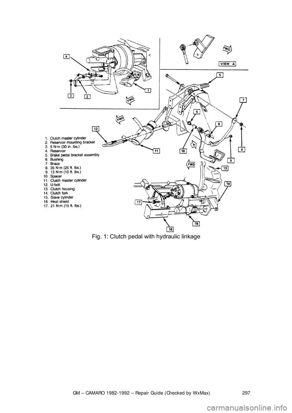
master cylinder/slave cylinder (hydraulic).
The hydraulic system utilizes a remote re servoir which is mounted to the power
brake booster, a master cy linder mounted to the cowl p anel and a slave cylinder
that is mounted to the bell housing. Th e system is operated directly by the
clutch pedal. When adding fl uid to the reservoir, always use a type which meets
DOT 3 specifications.
CAUTION - The clutch driven disc contains asbestos, which has been
determined to be a cancer causing agen t. Never clean clutch surfaces with
compressed air! Avoid inhaling any dus t from any clutch surface! When
cleaning clutch surfaces, use a commercia lly available brake cleaning fluid.
FREE-PLAY ADJUSTMENT
MECHANICAL LINKAGE 1. Disconnect the return sp ring at the clutch fork.
2. Hold the pedal against the rubber bumper on the dash brace.
3. Push the clutch fork so that th e throwout bearing lightly contacts the
pressure plate fingers.
Page 296 of 875
GM – CAMARO 1982-1992 – Repair Guide (Checked by WxMax) 296
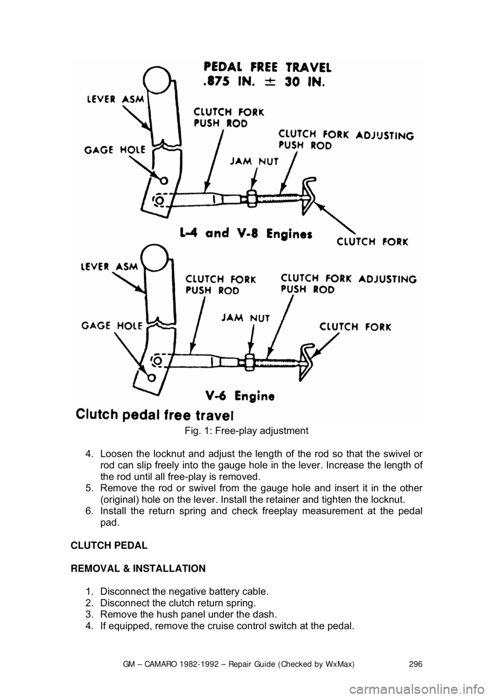
Fig. 1: Free-play adjustment
4. Loosen the locknut and adjust the length of the rod so that the swivel or
rod can slip freely into the gauge hole in the lever. Increase the length of
the rod until all free-play is removed.
5. Remove the rod or swivel from the gauge hole and insert it in the other
(original) hole on the lever. Install the retainer and tighten the loc\
knut.
6. Install the return spring and che ck freeplay measurement at the pedal
pad.
CLUTCH PEDAL
REMOVAL & INSTALLATION 1. Disconnect the negative battery cable.
2. Disconnect the clutch return spring.
3. Remove the hush panel under the dash.
4. If equipped, remove the cruise control switch at the pedal.
Page 297 of 875
GM – CAMARO 1982-1992 – Repair Guide (Checked by WxMax) 297
Fig. 1: Clutch pedal with hydraulic linkage
Page 298 of 875
GM – CAMARO 1982-1992 – Repair Guide (Checked by WxMax) 298
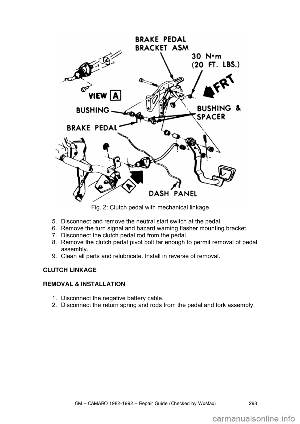
Fig. 2: Clutch pedal with mechanical linkage
5. Disconnect and remove the neutra l start switch at the pedal.
6. Remove the turn signal and hazard warning flasher mounting bracket.
7. Disconnect the clutch pedal rod from the pedal.
8. Remove the clutch pedal pivot bolt far enough to permit removal of pedal\
assembly.
9. Clean all parts and relubricate. Install in reverse of removal.
CLUTCH LINKAGE
REMOVAL & INSTALLATION 1. Disconnect the negative battery cable.
2. Disconnect the return spring and rods from the pedal and fork assembly.
Page 299 of 875
GM – CAMARO 1982-1992 – Repair Guide (Checked by WxMax) 299
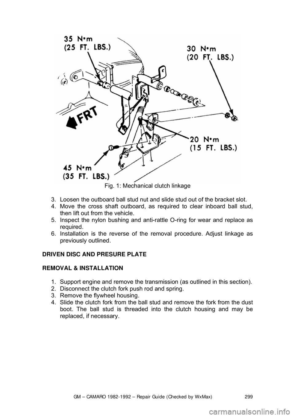
Fig. 1: Mechanical clutch linkage
3. Loosen the outboard ball stud nut and slid e stud out of the bracket slot.
4. Move the cross shaft outboard, as required to clear inboard ball stud,
then lift out from the vehicle.
5. Inspect the nylon bushing and anti-ra ttle O-ring for wear and replace as
required.
6. Installation is the reverse of th e removal procedure. Adjust linkage as
previously outlined.
DRIVEN DISC AND PRESURE PLATE
REMOVAL & INSTALLATION 1. Support engine and remove the transmissi on (as outlined in this section).
2. Disconnect the clutch fork push rod and spring.
3. Remove the flywheel housing.
4. Slide the clutch fork from the ball stud and remove the fork from the dust
boot. The ball stud is threaded into the clutch housing and may be
replaced, if necessary.
Page 300 of 875
GM – CAMARO 1982-1992 – Repair Guide (Checked by WxMax) 300
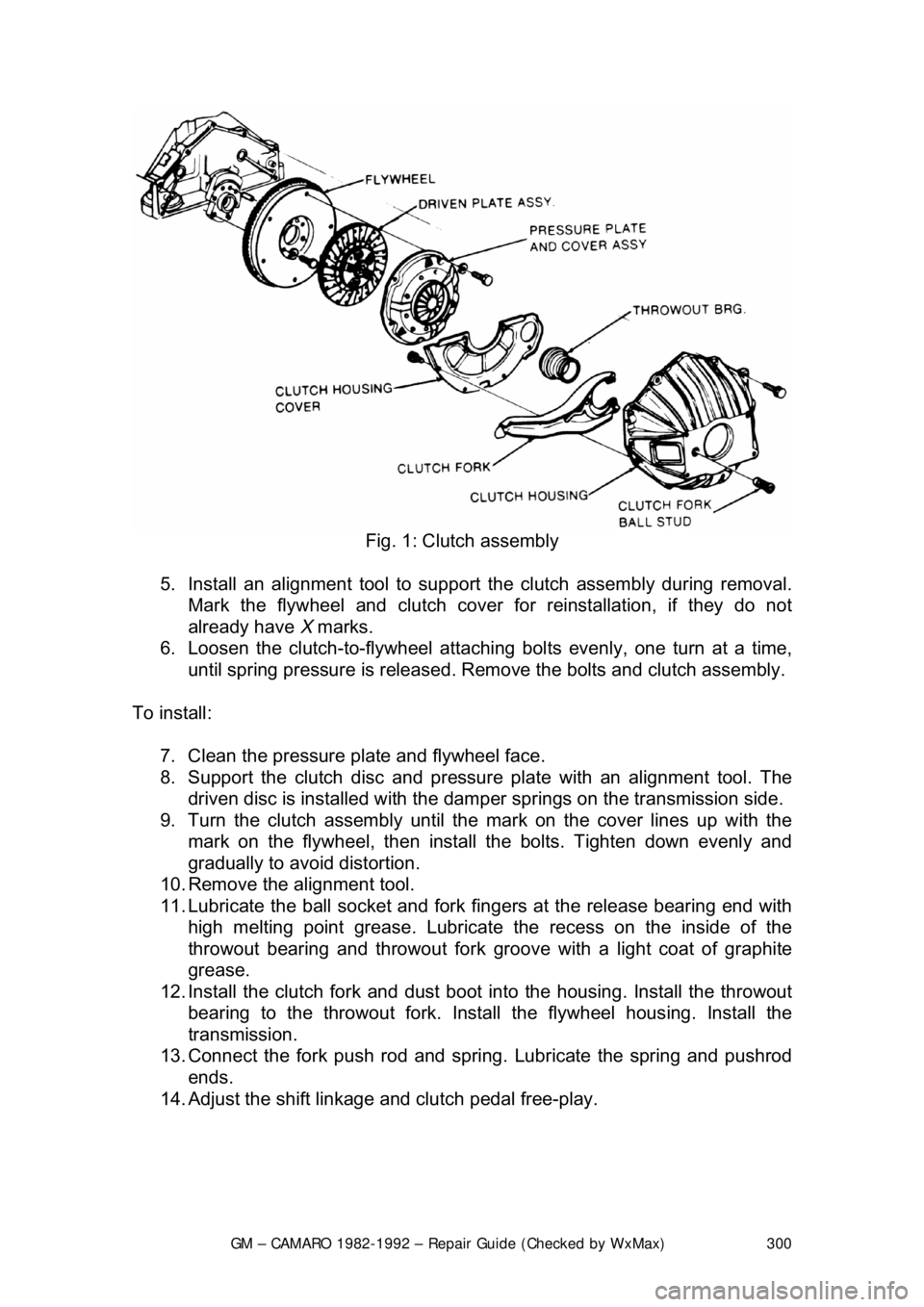
Fig. 1: Clutch assembly
5. Install an alignment tool to support the clutch assembly during removal.
Mark the flywheel and clutch cover for reinstallation, if they do not
already have X marks.
6. Loosen the clutch-to-flywheel attachi ng bolts evenly, one turn at a time,
until spring pressure is released. Remo ve the bolts and clutch assembly.
To install: 7. Clean the pressure plate and flywheel face.
8. Support the clutch di sc and pressure plate with an alignment tool. The
driven disc is installed with the damper springs on the transmission side.
9. Turn the clutch assembly until t he mark on the cover lines up with the
mark on the flywheel, then install t he bolts. Tighten down evenly and
gradually to avoid distortion.
10. Remove the alignment tool.
11. Lubricate the ball socket and fork fi ngers at the release bearing end with
high melting point greas e. Lubricate the recess on the inside of the
throwout bearing and throwout fork groove with a light coat of graphite
grease.
12. Install the clutch fork and dust boot into the housing. Install the throwout
bearing to the throwout fork. Insta ll the flywheel housing. Install the
transmission.
13. Connect the fork push rod and spri ng. Lubricate the spring and pushrod
ends.
14. Adjust the shift linkage and clutch pedal free-play.