CHEVROLET CAMARO 1982 Repair Guide
Manufacturer: CHEVROLET, Model Year: 1982, Model line: CAMARO, Model: CHEVROLET CAMARO 1982Pages: 875, PDF Size: 88.64 MB
Page 631 of 875
GM – CAMARO 1982-1992 – Repair Guide (Checked by WxMax) 631
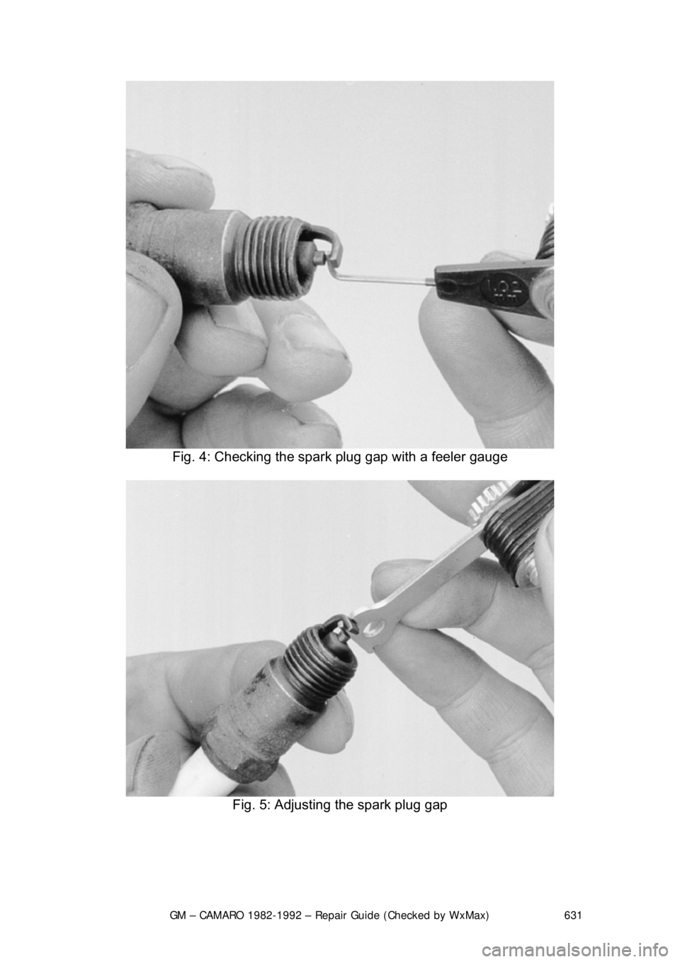
Fig. 4: Checking the spark plug gap with a feeler gauge
Fig. 5: Adjusting the spark plug gap
Page 632 of 875
GM – CAMARO 1982-1992 – Repair Guide (Checked by WxMax) 632
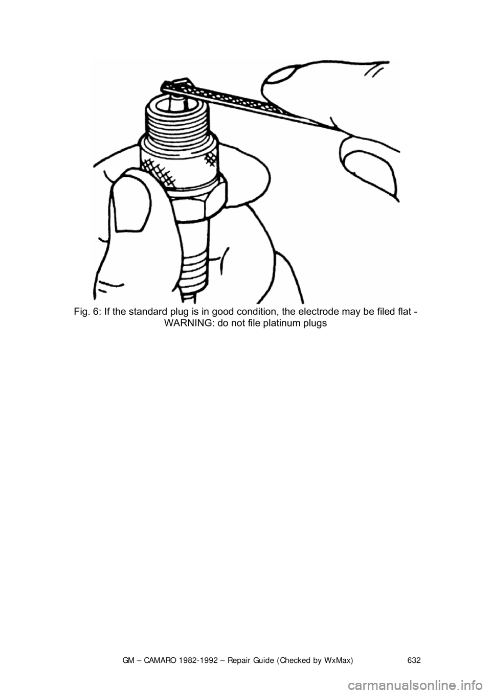
Fig. 6: If the standard plug is in good c ondition, the electrode may be filed flat -
WARNING: do not file platinum plugs
Page 633 of 875
GM – CAMARO 1982-1992 – Repair Guide (Checked by WxMax) 633
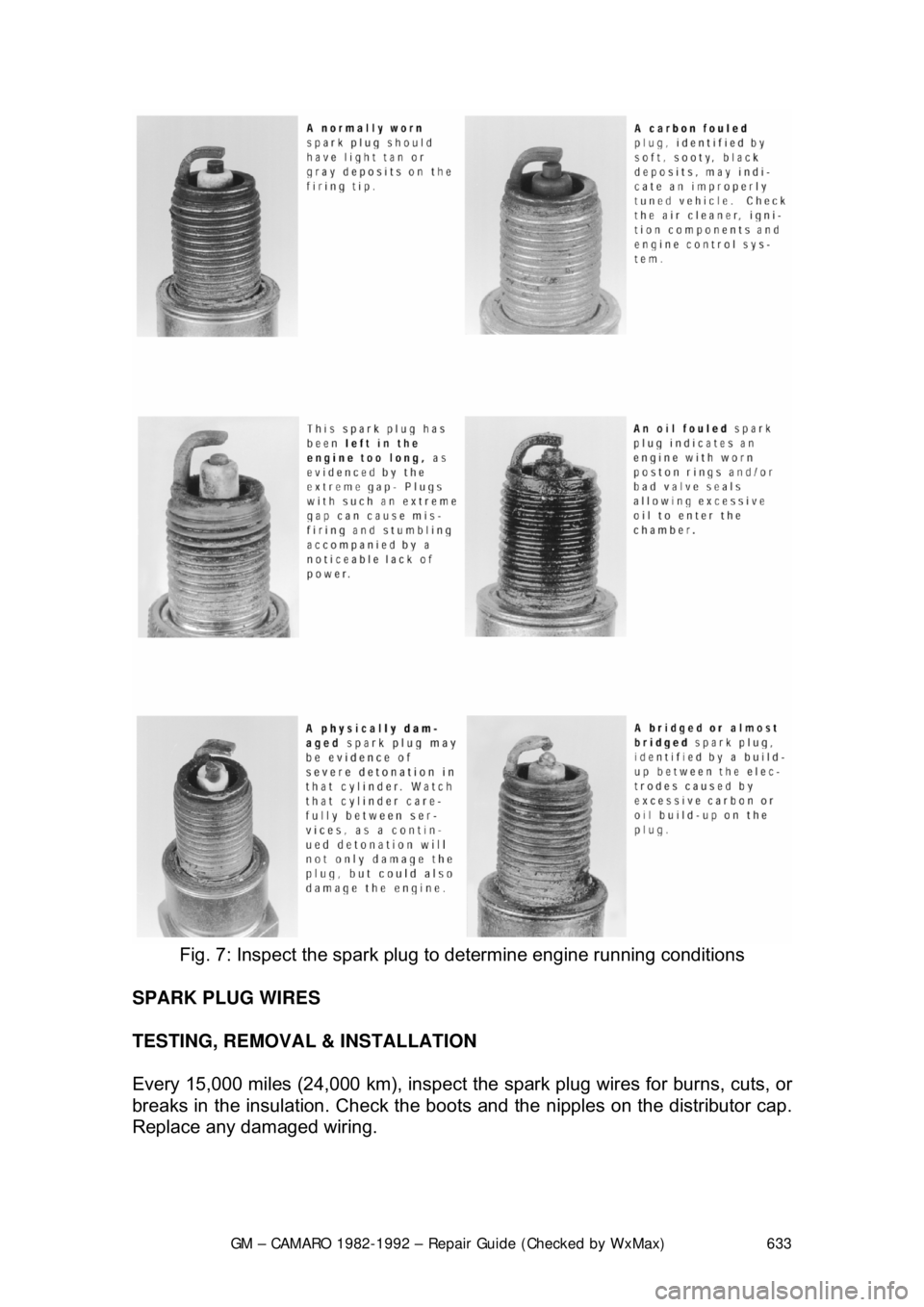
Fig. 7: Inspect the spark plug to determine engine running conditions
SPARK PLUG WIRES
TESTING, REMOVAL & INSTALLATION
Every 15,000 miles (24,000 km), inspect the spark plug wires for burns, cuts, or
breaks in the insulation. Check the boots and the nipples on the distributor cap.
Replace any damaged wiring.
Page 634 of 875
GM – CAMARO 1982-1992 – Repair Guide (Checked by WxMax) 634
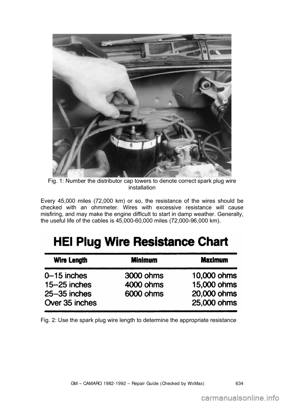
Fig. 1: Number the distributor cap to wers to denote correct spark plug wire
installation
Every 45,000 miles (72,000 km) or so, th e resistance of the wires should be
checked with an ohmmeter. Wires wit h excessive resistance will cause
misfiring, and may make the engine difficult to start in damp weather. Generally,
the useful life of the cables is 45,000-60,000 miles (72,000-96,000 km).
Fig. 2: Use the spark plug wire length to determine the appropriate resistance
Page 635 of 875
GM – CAMARO 1982-1992 – Repair Guide (Checked by WxMax) 635
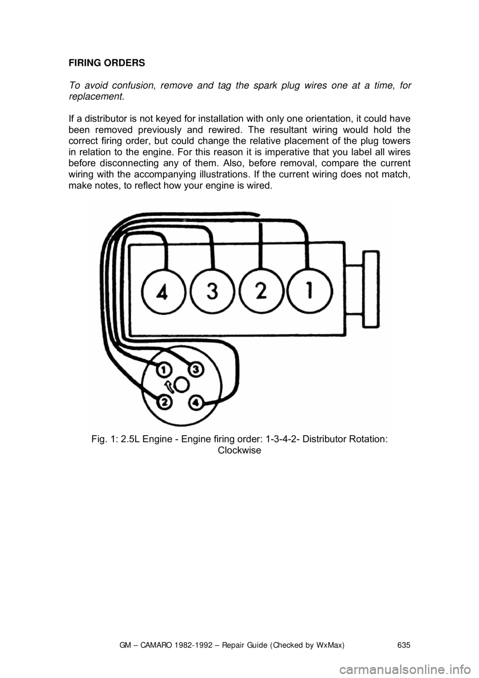
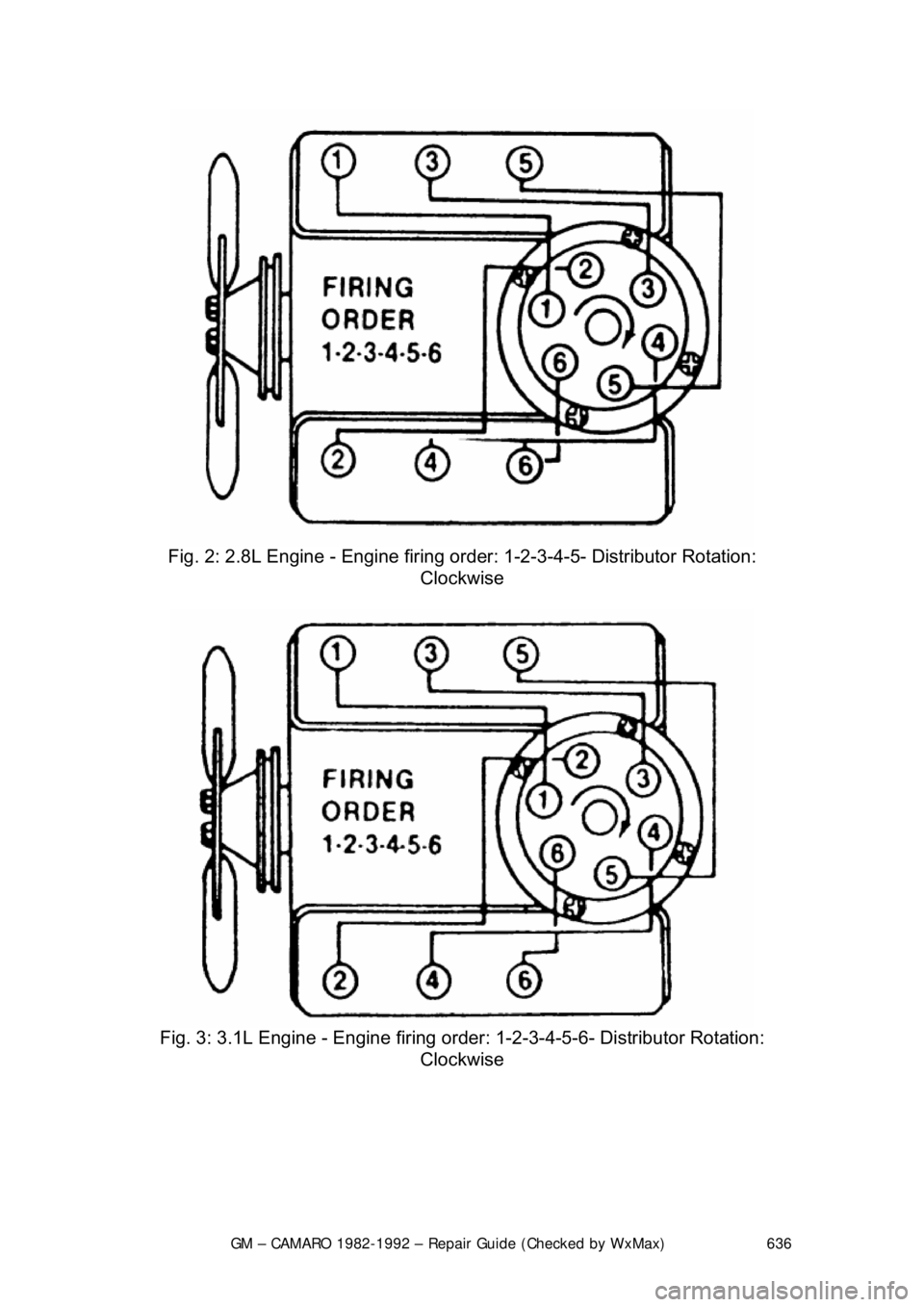
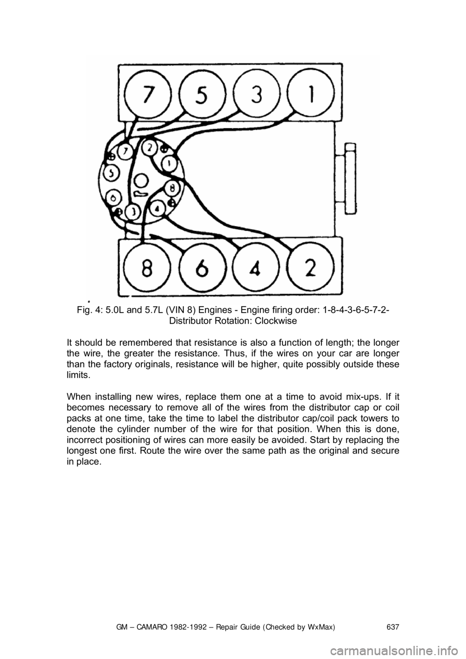
FIRING ORDERS
To avoid confusion, remove and tag th
e spark plug wires one at a time, for
replacement.
If a distributor is not keyed for installati on with only one orientation, it could have
been removed previously and rewired. Th e resultant wiring would hold the
correct firing order, but could change the relative placement of the plug towers
in relation to the engine. Fo r this reason it is imperative that you label all wires
before disconnecting any of them. Also, before removal, compare the current
wiring with the accompanying i llustrations. If the current wiring does not match,
make notes, to reflect how your engine is wired.
Fig. 1: 2.5L Engine - Engine firing or der: 1-3-4-2- Distributor Rotation:
Clockwise
Page 636 of 875
GM – CAMARO 1982-1992 – Repair Guide (Checked by WxMax) 636
Fig. 2: 2.8L Engine - Engine firing or der: 1-2-3-4-5- Distributor Rotation:
Clockwise
Fig. 3: 3.1L Engine - Engine firing order : 1-2-3-4-5-6- Distributor Rotation:
Clockwise
Page 637 of 875
GM – CAMARO 1982-1992 – Repair Guide (Checked by WxMax) 637
Fig. 4: 5.0L and 5.7L (VIN 8) Engines - Engine firing order: 1-8-4-3-6-5-7-2-
Distributor Rotation: Clockwise
It should be remembered that resistance is also a function of length; the longer
the wire, the greater the re sistance. Thus, if the wires on your car are longer
than the factory originals, resistance will be higher, qui te possibly outside these
limits.
When installing new wires, r eplace them one at a time to avoid mix-ups. If it
becomes necessary to remove all of the wires from the distributor cap or coil
packs at one time, take the time to label the distributor cap/coil pack towers to
denote the cylinder number of the wire fo r that position. When this is done,
incorrect positioning of wires can more eas ily be avoided. Start by replacing the
longest one first. Route the wire over the same path as the original and secure
in place.
Page 638 of 875
GM – CAMARO 1982-1992 – Repair Guide (Checked by WxMax) 638
ELECTRONIC IGNITION SYSTEM
GENERAL INFORMATION
The High Energy Ignition (HEI) system
controls the fuel combustion by
providing a spark to ignite the compress ed air/fuel mixture at the correct time.
To provide improved engine performance, fuel economy, and control of exhaust
emissions, the engine contro l module (ECM) controls distributor spark advance
(timing) with an ignition control system.
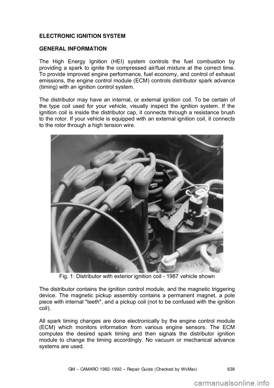
The distributor may have an internal, or ex ternal ignition coil. To be certain of
the type coil used for your vehicle, vis ually inspect the ignition system. If the
ignition coil is inside the distributor c ap, it connects through a resistance brush
to the rotor. If your vehicle is equipped with an external ignition coil, it connects
to the rotor through a high tension wire.
Fig. 1: Distributor with exterior ignition coil - 1987 vehicle shown
The distributor contains the ignition c ontrol module, and the magnetic triggering
device. The magnetic pickup assembly contains a permanent magnet, a pole
piece with internal "teeth", and a pickup co il (not to be confused with the ignition
coil).
All spark timing changes are done electr onically by the engine control module
(ECM) which monitors information from various engine sensors. The ECM
computes the desired spark timing and t hen signals the distributor ignition
module to change the timing accordingly. No vacuum or mechanical advance
systems are used.
Page 639 of 875

GM – CAMARO 1982-1992 – Repair Guide (Checked by WxMax) 639
In the HEI system, as in other electr
onic ignition systems, the breaker points
have been replaced wit h an electronic switch - a tr ansistor - which is located
within the ignition module. This switching transistor pe rforms the same function
the points did in a conventi onal ignition system; it simply turns the coil's primary
current on and off at the correct time. Essentially, electronic and conventional
ignition systems operate on t he same principle.
The module which houses the switching transistor is controlled (turned on and
off) by a magnetically gener ated impulse induced in the pickup coil. When the
teeth of the rotating timer align with t he teeth of the pole piece, the induced
voltage in the pickup coil signals the elec tronic module to open the coil primary
circuit. The primary current then decreases, and a high voltage is induced in the
ignition coil secondary windings, which is then directed through the rotor and
high voltage leads (spark plug wires) to fire the spark plugs.
In essence, the pickup coil module system simply replaces the conventional
breaker points and condenser. The condenser found within the distributor is for
radio suppression purposes only and has nothing to do with the ignition
process. The ignition module automatically controls the dwell period, increasing
it with increasing en gine speed. Since dwell is co ntrolled in this manner, it
cannot be adjusted. The module itse lf is non-adjustable/non-repairable and
must be replaced if found defective.
SYSTEM PRECAUTIONS
Before proceeding with troubleshooting, ta ke note of the following precautions:
TIMING LIGHT USE
Care should be exercised when connec ting a timing light or other pick-up
equipment. Do not force anything between the boots and wiring, or through the
silicone jacket. Connections should be made in parallel using an adapter.
Inductive pickup timing lights are the bes t kind to use with the ignition systems
covered by this information.
SPARK PLUG WIRES
The plug wires used with these systems are of a different construction than
conventional wires. When replacing them, make sure you get the correct wires,
since conventional wires will not carry the voltage. Also, handle the wires
carefully to avoid cracking or splitti ng them, and NEVER pierce the wires.
TACHOMETER USE
Not all tachometers will operate or indi cate correctly when used on an HEI or
C
3I system. While some tachometers ma y give a reading, this does not
necessarily mean the reading is correct. In addition, some tachometers hook up
differently from others. If you cannot fi gure out whether or not your tachometer
will work on your car, check with the tachometer manufacturer.
Page 640 of 875

GM – CAMARO 1982-1992 – Repair Guide (Checked by WxMax) 640
The tachometer terminal should never
be allowed to touch ground, as damage
to the computer control module and/or ignition coil assembly can result.
CONNECTORS
When disengaging connectors, do not use a screw driver or other tool to release
the locking tab, as this mi ght break the connector.
SYSTEM TESTERS
Instruments designed specific ally for testing HEI or C
3I systems are available
from several tool manufactur ers. Some of these will even test the module itself.
However, the tests given in the followin g section will require only an ohmmeter
and a voltmeter.
TESTING
The symptoms of a defective component within the HEI or C
3I system are
exactly the same as those you woul d encounter in a conventional system.
Some of these symptoms are:
• Hard or no starting
• Rough Idle
• Poor fuel economy
• Engine misses under load or while accelerating
PRELIMINARY CHECKS
If you suspect a problem in your igniti on system, there are certain preliminary
checks which you should carry out befor e you begin to check the electronic
portions of the system. First, it is extrem ely important to make sure the vehicle
battery is in a good state of charge. A defective or poorly charged battery will
cause the various components of the ignition system to read incorrectly when
they are being tested. Second, make su re all wiring connections are clean and
tight, not only at the battery, but also at the distributor cap (if so equipped),
ignition coil, camshaft and/or crankshaft sensors (if so equipped) and at the
control module.
Since the only difference between these ignition systems lies before the spark
plug wiring, it is important to check the secondary ig nition circuit first. If the
secondary circuit checks out properly (ther e is spark), then the engine condition
is probably not the fault of the ignition system. To check the secondary ignition
system, perform a simple spark test. Remove one of the plug wires and insert
some sort of extension in the plug socket. An old spark plug with the ground
electrode removed makes a good extension. Hold the wire and extension using
an insulated tool (NOT BY HAND) about
1/4 in. (6mm) away from the block and
crank the engine. If a normal spark occurs, then the problem is most likely not in
the ignition system. Check for fuel system problems, or fouled spark plugs.