engine mount CHRYSLER CARAVAN 2002 Service Manual
[x] Cancel search | Manufacturer: CHRYSLER, Model Year: 2002, Model line: CARAVAN, Model: CHRYSLER CARAVAN 2002Pages: 2399, PDF Size: 57.96 MB
Page 1251 of 2399
INSTALLATION
(1) Install the front mount bracket to engine, if
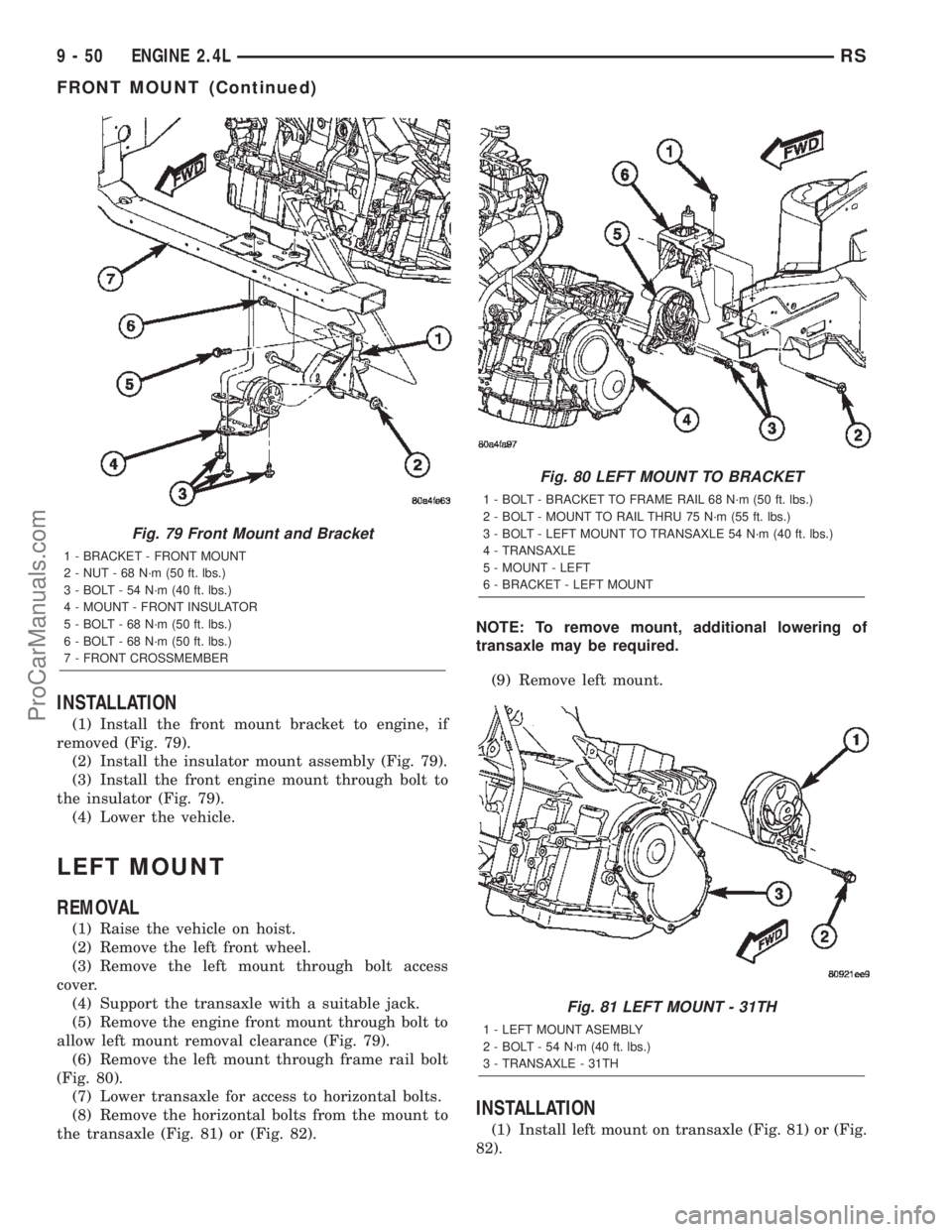
removed (Fig. 79).
(2) Install the insulator mount assembly (Fig. 79).
(3) Install the front engine mount through bolt to
the insulator (Fig. 79).
(4) Lower the vehicle.
LEFT MOUNT
REMOVAL
(1) Raise the vehicle on hoist.
(2) Remove the left front wheel.
(3) Remove the left mount through bolt access
cover.
(4) Support the transaxle with a suitable jack.
(5) Remove the engine front mount through bolt to
allow left mount removal clearance (Fig. 79).
(6) Remove the left mount through frame rail bolt
(Fig. 80).
(7) Lower transaxle for access to horizontal bolts.
(8) Remove the horizontal bolts from the mount to
the transaxle (Fig. 81) or (Fig. 82).NOTE: To remove mount, additional lowering of
transaxle may be required.
(9) Remove left mount.
INSTALLATION
(1) Install left mount on transaxle (Fig. 81) or (Fig.
82).
Fig. 79 Front Mount and Bracket
1 - BRACKET - FRONT MOUNT
2 - NUT - 68 N´m (50 ft. lbs.)
3 - BOLT - 54 N´m (40 ft. lbs.)
4 - MOUNT - FRONT INSULATOR
5 - BOLT - 68 N´m (50 ft. lbs.)
6 - BOLT - 68 N´m (50 ft. lbs.)
7 - FRONT CROSSMEMBER
Fig. 80 LEFT MOUNT TO BRACKET
1 - BOLT - BRACKET TO FRAME RAIL 68 N´m (50 ft. lbs.)
2 - BOLT - MOUNT TO RAIL THRU 75 N´m (55 ft. lbs.)
3 - BOLT - LEFT MOUNT TO TRANSAXLE 54 N´m (40 ft. lbs.)
4 - TRANSAXLE
5 - MOUNT - LEFT
6 - BRACKET - LEFT MOUNT
Fig. 81 LEFT MOUNT - 31TH
1 - LEFT MOUNT ASEMBLY
2 - BOLT - 54 N´m (40 ft. lbs.)
3 - TRANSAXLE - 31TH
9 - 50 ENGINE 2.4LRS
FRONT MOUNT (Continued)
ProCarManuals.com
Page 1252 of 2399
(2) Raise transaxle with jack until left mount is in
position.
(3) Install left mount through bolt (Fig. 80).
(4) Install left mount through bolt access cover.
(5) Install front mount through bolt (Fig. 79).
(6) Install left front wheel.
(7) Lower vehicle.
REAR MOUNT
REMOVAL
(1) Raise vehicle on hoist.
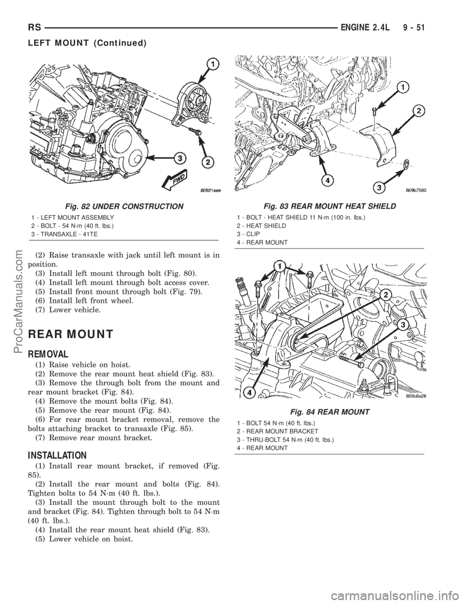
(2) Remove the rear mount heat shield (Fig. 83).
(3) Remove the through bolt from the mount and
rear mount bracket (Fig. 84).
(4) Remove the mount bolts (Fig. 84).
(5) Remove the rear mount (Fig. 84).
(6) For rear mount bracket removal, remove the
bolts attaching bracket to transaxle (Fig. 85).
(7) Remove rear mount bracket.
INSTALLATION
(1) Install rear mount bracket, if removed (Fig.
85).
(2) Install the rear mount and bolts (Fig. 84).
Tighten bolts to 54 N´m (40 ft. lbs.).
(3) Install the mount through bolt to the mount
and bracket (Fig. 84). Tighten through bolt to 54 N´m
(40 ft. lbs.).
(4) Install the rear mount heat shield (Fig. 83).
(5) Lower vehicle on hoist.
Fig. 82 UNDER CONSTRUCTION
1 - LEFT MOUNT ASSEMBLY
2 - BOLT - 54 N´m (40 ft. lbs.)
3 - TRANSAXLE - 41TE
Fig. 83 REAR MOUNT HEAT SHIELD
1 - BOLT - HEAT SHIELD 11 N´m (100 in. lbs.)
2 - HEAT SHIELD
3 - CLIP
4 - REAR MOUNT
Fig. 84 REAR MOUNT
1 - BOLT 54 N´m (40 ft. lbs.)
2 - REAR MOUNT BRACKET
3 - THRU-BOLT 54 N´m (40 ft. lbs.)
4 - REAR MOUNT
RSENGINE 2.4L9-51
LEFT MOUNT (Continued)
ProCarManuals.com
Page 1253 of 2399
RIGHT MOUNT
REMOVAL
(1) Remove air cleaner housing lid and clean air
hose from throttle body.
(2) Remove air cleaner element and housing.
(3) Disconnect make-up air hose from cylinder
head cover.
(4) Remove the load on the right engine mount by
carefully supporting the engine assembly with a floor
jack.
(5) Disconnect electrical harness support clips from
engine mount bracket.
(6) Remove the vertical bolts attaching the engine
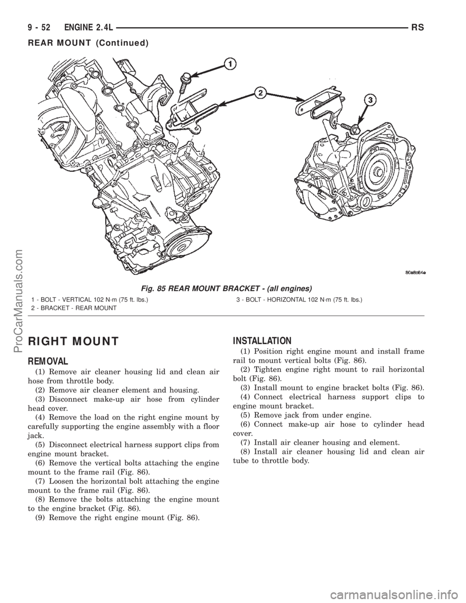
mount to the frame rail (Fig. 86).
(7) Loosen the horizontal bolt attaching the engine
mount to the frame rail (Fig. 86).
(8) Remove the bolts attaching the engine mount
to the engine bracket (Fig. 86).
(9) Remove the right engine mount (Fig. 86).
INSTALLATION
(1) Position right engine mount and install frame
rail to mount vertical bolts (Fig. 86).
(2) Tighten engine right mount to rail horizontal
bolt (Fig. 86).
(3) Install mount to engine bracket bolts (Fig. 86).
(4) Connect electrical harness support clips to
engine mount bracket.
(5) Remove jack from under engine.
(6) Connect make-up air hose to cylinder head
cover.
(7) Install air cleaner housing and element.
(8) Install air cleaner housing lid and clean air
tube to throttle body.
Fig. 85 REAR MOUNT BRACKET - (all engines)
1 - BOLT - VERTICAL 102 N´m (75 ft. lbs.)
2 - BRACKET - REAR MOUNT3 - BOLT - HORIZONTAL 102 N´m (75 ft. lbs.)
9 - 52 ENGINE 2.4LRS
REAR MOUNT (Continued)
ProCarManuals.com
Page 1254 of 2399
LUBRICATION
DESCRIPTION
The lubrication system is a full-flow filtration,
pressure feed type. The oil pump is mounted in the
front engine cover and driven by the crankshaft.
OPERATION
Engine oil drawn up through the pickup tube and
is pressurized by the oil pump and routed through
the full-flow filter to the main oil gallery running the
length of the cylinder block. A diagonal hole in each
bulkhead feeds oil to each main bearing. Drilled pas-
sages within the crankshaft route oil from main bear-
ing journals to connecting rod journals. Balance shaft
lubrication is provided through an oil passage from
the number one main bearing cap through the bal-
ance shaft carrier support leg. This passage directly
supplies oil to the front bearings and internal
machined passages in the shafts that routes oil from
front to the rear shaft bearing journals. A vertical
hole at the number five bulkhead routes pressurized
oil through a restrictor (integral to the cylinder head
gasket) up past a cylinder head bolt to an oil galleryrunning the length of the cylinder head. The cam-
shaft journals are partially slotted to allow a prede-
termined amount of pressurized oil to pass into the
bearing cap cavities. Lubrication of the camshaft
lobes are provided by small holes in the camshaft
bearing caps that are directed towards each lobe. Oil
returning to the pan from pressurized components
supplies lubrication to the valve stems. Cylinder
bores and wrist pins are splash lubricated from
directed slots on the connecting rod thrust collars.
DIAGNOSIS AND TESTING - CHECKING
ENGINE OIL PRESSURE
(1) Disconnect and remove oil pressure switch.
(Refer to 9 - ENGINE/LUBRICATION/OIL PRES-
SURE SENSOR/SWITCH - REMOVAL)
(2) Install Special Tools C-3292 Gauge with 8406
Adaptor fitting.
(3) Start engine and record oil pressure. Refer to
Specifications for correct oil pressure requirements.
(Refer to 9 - ENGINE - SPECIFICATIONS)
CAUTION: If oil pressure is 0 at idle, do not perform
the 3000 RPM test
(4) If oil pressure is 0 at idle. Shut off engine,
check for pressure relief valve stuck open, a clogged
oil pick-up screen or a damaged oil pick-up tube
O-ring.
(5) After test is complete, remove test gauge and
fitting.
(6) Install oil pressure switch and connector. (Refer
to 9 - ENGINE/LUBRICATION/OIL PRESSURE
SENSOR/SWITCH - INSTALLATION)
OIL
STANDARD PROCEDURE
ENGINE OIL LEVEL CHECK
The best time to check engine oil level is after it
has sat overnight, or if the engine has been running,
allow the engine to be shut off for at least 5 minutes
before checking oil level.
Checking the oil while the vehicle is on level
ground will improve the accuracy of the oil level
reading. Remove dipstick and observe oil level. Add
oil only when the level is at or below the ADD mark
(Fig. 87).
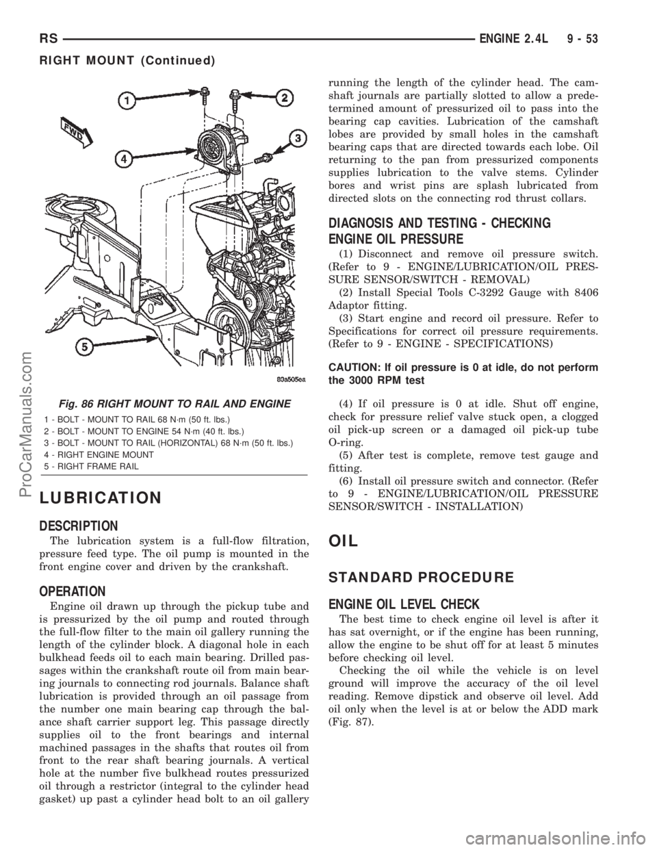
Fig. 86 RIGHT MOUNT TO RAIL AND ENGINE
1 - BOLT - MOUNT TO RAIL 68 N´m (50 ft. lbs.)
2 - BOLT - MOUNT TO ENGINE 54 N´m (40 ft. lbs.)
3 - BOLT - MOUNT TO RAIL (HORIZONTAL) 68 N´m (50 ft. lbs.)
4 - RIGHT ENGINE MOUNT
5 - RIGHT FRAME RAIL
RSENGINE 2.4L9-53
RIGHT MOUNT (Continued)
ProCarManuals.com
Page 1255 of 2399
STANDARD PROCEDURE - ENGINE OIL AND
FILTER CHANGE
Change engine oil at mileage and time intervals
described in the Maintenance Schedule. (Refer to
LUBRICATION & MAINTENANCE/MAINTE-
NANCE SCHEDULES - DESCRIPTION)
WARNING: NEW OR USED ENGINE OIL CAN BE
IRRITATING TO THE SKIN. AVOID PROLONGED OR
REPEATED SKIN CONTACT WITH ENGINE OIL.
CONTAMINANTS IN USED ENGINE OIL, CAUSED BY
INTERNAL COMBUSTION, CAN BE HAZARDOUS TO
YOUR HEALTH. THOROUGHLY WASH EXPOSED
SKIN WITH SOAP AND WATER. DO NOT WASH
SKIN WITH GASOLINE, DIESEL FUEL, THINNER, OR
SOLVENTS, HEALTH PROBLEMS CAN RESULT. DO
NOT POLLUTE, DISPOSE OF USED ENGINE OIL
PROPERLY. CONTACT YOUR DEALER OR GOVERN-
MENT AGENCY FOR LOCATION OF COLLECTION
CENTER IN YOUR AREA.
Run engine until achieving normal operating tem-
perature.
(1) Position the vehicle on a level surface and turn
engine off.
(2) Remove oil fill cap.
(3) Hoist and support vehicle on safety stands.
Refer to Hoisting and Jacking Recommendations.
(Refer to LUBRICATION & MAINTENANCE/HOIST-
ING - STANDARD PROCEDURE)
(4) Place a suitable drain pan under crankcase
drain.
(5) Remove drain plug from crankcase and allow
oil to drain into pan. Inspect drain plug threads for
stretching or other damage. Replace drain plug and
gasket if damaged.
(6) Remove oil filter. (Refer to 9 - ENGINE/LUBRI-
CATION/OIL FILTER - REMOVAL)
(7) Install and tighten drain plug in crankcase.
(8) Install new oil filter. (Refer to 9 - ENGINE/LU-
BRICATION/OIL FILTER - INSTALLATION)
(9) Lower vehicle and fill crankcase with specified
type and amount of engine oil. (Refer to LUBRICA-
TION & MAINTENANCE/FLUID TYPES -
DESCRIPTION)
(10) Install oil fill cap.
(11) Start engine and inspect for leaks.(12) Stop engine and inspect oil level.
NOTE: Care should be exercised when disposing
used engine oil after it has been drained from a
vehicle engine. Refer to the WARNING listed above.
OIL FILTER
DESCRIPTION
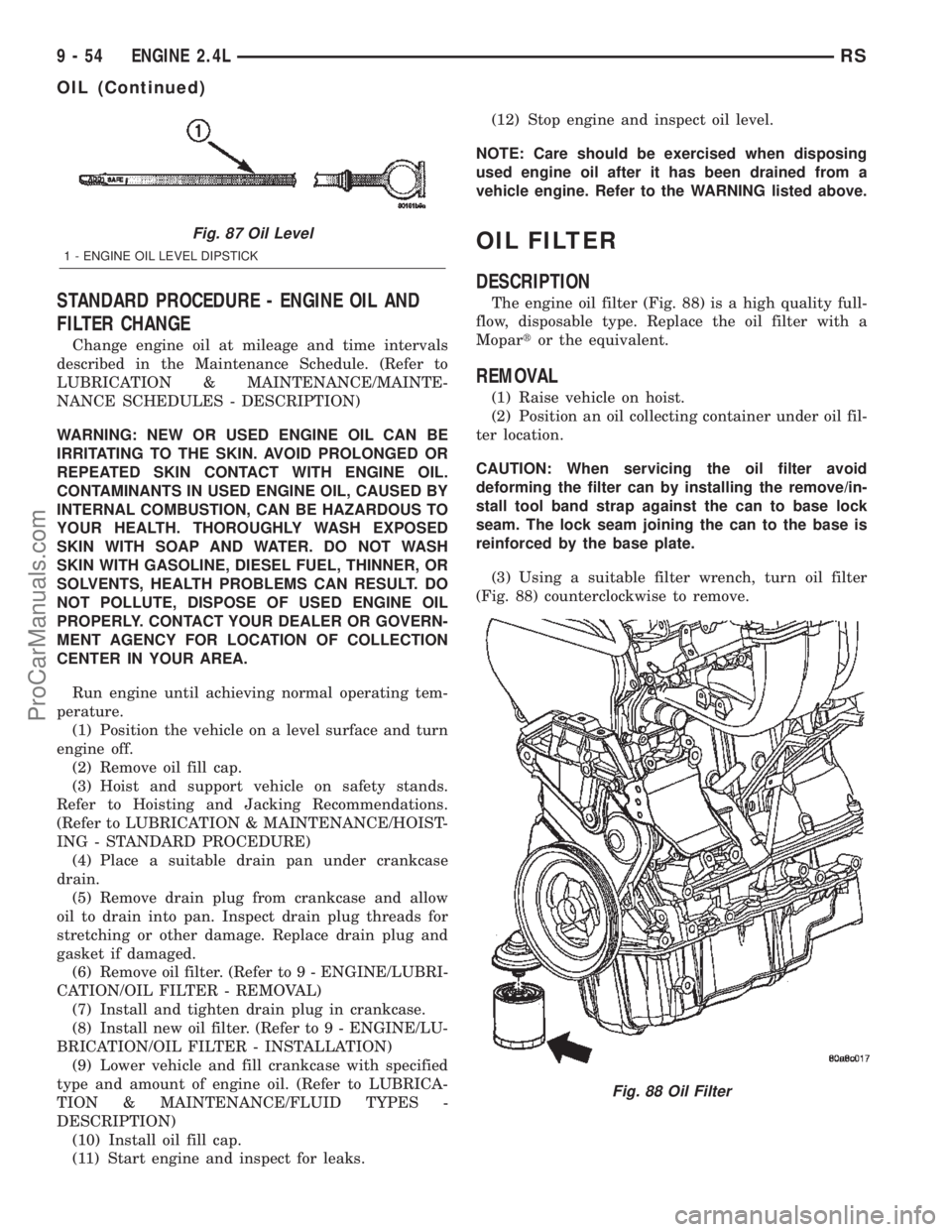
The engine oil filter (Fig. 88) is a high quality full-
flow, disposable type. Replace the oil filter with a
Mopartor the equivalent.
REMOVAL
(1) Raise vehicle on hoist.
(2) Position an oil collecting container under oil fil-
ter location.
CAUTION: When servicing the oil filter avoid
deforming the filter can by installing the remove/in-
stall tool band strap against the can to base lock
seam. The lock seam joining the can to the base is
reinforced by the base plate.
(3) Using a suitable filter wrench, turn oil filter
(Fig. 88) counterclockwise to remove.
Fig. 87 Oil Level
1 - ENGINE OIL LEVEL DIPSTICK
Fig. 88 Oil Filter
9 - 54 ENGINE 2.4LRS
OIL (Continued)
ProCarManuals.com
Page 1256 of 2399
INSTALLATION
(1) Clean and check filter mounting surface. The
surface must be smooth, flat and free of debris or
pieces of gasket.
(2) Lubricate new oil filter gasket with clean
engine oil.
(3) Screw oil filter (Fig. 88) on until the gasket
contacts base. Tighten to 12 N´m (105 in. lbs.).
OIL PAN
REMOVAL
(1) Raise vehicle on hoist and drain engine oil.
(2) Remove structural collar. (Refer to 9 -
ENGINE/ENGINE BLOCK/STRUCTURAL COVER -
REMOVAL)
(3) Remove air conditioning compressor bracket to
oil pan bolt.
(4) Remove bolts attaching oil pan.
(5) Remove oil pan.
(6) Clean oil pan and all gasket surfaces.
INSTALLATION
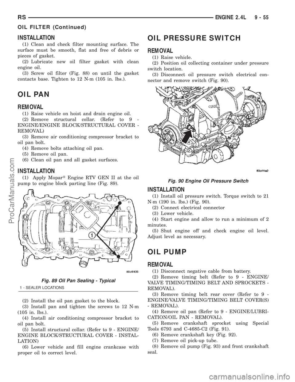
(1) Apply MopartEngine RTV GEN II at the oil
pump to engine block parting line (Fig. 89).
(2) Install the oil pan gasket to the block.
(3) Install pan and tighten the screws to 12 N´m
(105 in. lbs.).
(4) Install air conditioning compressor bracket to
oil pan bolt.
(5) Install structural collar. (Refer to 9 - ENGINE/
ENGINE BLOCK/STRUCTURAL COVER - INSTAL-
LATION)
(6) Lower vehicle and fill engine crankcase with
proper oil to correct level.
OIL PRESSURE SWITCH
REMOVAL
(1) Raise vehicle.
(2) Position oil collecting container under pressure
switch location.
(3) Disconnect oil pressure switch electrical con-
nector and remove switch (Fig. 90).
INSTALLATION
(1) Install oil pressure switch. Torque switch to 21
N´m (190 in. lbs.) (Fig. 90).
(2) Connect electrical connector
(3) Lower vehicle.
(4) Start engine and allow to run a minimum of 2
minutes.
(5) Shut engine off and check engine oil level.
Adjust level as necessary.
OIL PUMP
REMOVAL
(1) Disconnect negative cable from battery.
(2) Remove timing belt (Refer to 9 - ENGINE/
VALVE TIMING/TIMING BELT AND SPROCKETS -
REMOVAL).
(3) Remove timing belt rear cover (Refer to 9 -
ENGINE/VALVE TIMING/TIMING BELT COVER(S)
- REMOVAL).
(4) Remove oil pan (Refer to 9 - ENGINE/LUBRI-
CATION/OIL PAN - REMOVAL).
(5) Remove crankshaft sprocket using Special
Tools 6793 and C-4685-C2 (Fig. 91).
(6) Remove crankshaft key (Fig. 92).
(7) Remove oil pick-up tube.
(8) Remove oil pump (Fig. 93) and front crankshaft
seal.
Fig. 89 Oil Pan Sealing - Typical
1 - SEALER LOCATIONS
Fig. 90 Engine Oil Pressure Switch
RSENGINE 2.4L9-55
OIL FILTER (Continued)
ProCarManuals.com
Page 1264 of 2399
(2) Attach exhaust pipe to exhaust manifold and
tighten fasteners to 37 N´m (27 ft. lbs.).
(3) Install and connect the oxygen sensor. (Refer to
14 - FUEL SYSTEM/FUEL INJECTION/O2 SENSOR
- COMPONENT LOCATION)
TIMING BELT COVER(S)
REMOVAL
FRONT COVER
(1) Remove crankshaft vibration damper. (Refer to
9 - ENGINE/ENGINE BLOCK/VIBRATION
DAMPER - REMOVAL)
(2) Remove generator drive belt tensioner assem-
bly. (Refer to 7 - COOLING/ACCESSORY DRIVE/
BELT TENSIONERS - REMOVAL)
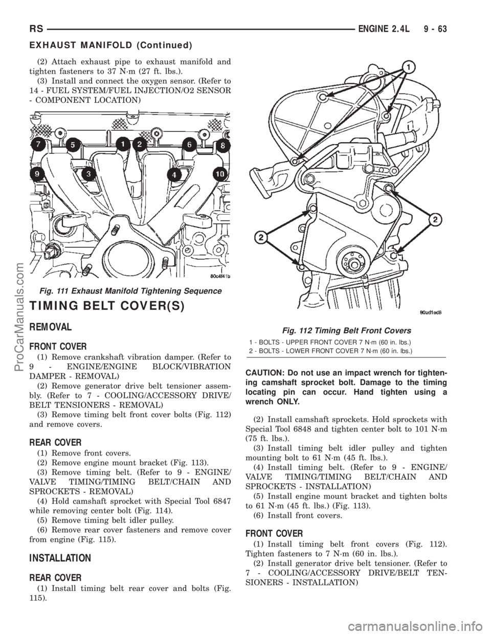
(3) Remove timing belt front cover bolts (Fig. 112)
and remove covers.
REAR COVER
(1) Remove front covers.
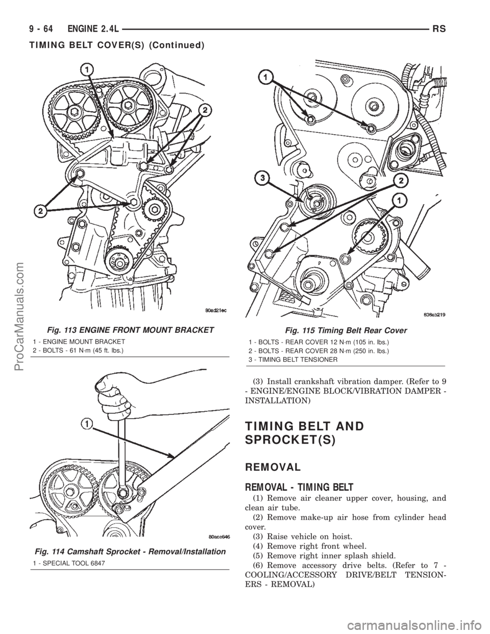
(2) Remove engine mount bracket (Fig. 113).
(3) Remove timing belt. (Refer to 9 - ENGINE/
VALVE TIMING/TIMING BELT/CHAIN AND
SPROCKETS - REMOVAL)
(4) Hold camshaft sprocket with Special Tool 6847
while removing center bolt (Fig. 114).
(5) Remove timing belt idler pulley.
(6) Remove rear cover fasteners and remove cover
from engine (Fig. 115).
INSTALLATION
REAR COVER
(1) Install timing belt rear cover and bolts (Fig.
115).CAUTION: Do not use an impact wrench for tighten-
ing camshaft sprocket bolt. Damage to the timing
locating pin can occur. Hand tighten using a
wrench ONLY.
(2) Install camshaft sprockets. Hold sprockets with
Special Tool 6848 and tighten center bolt to 101 N´m
(75 ft. lbs.).
(3) Install timing belt idler pulley and tighten
mounting bolt to 61 N´m (45 ft. lbs.).
(4) Install timing belt. (Refer to 9 - ENGINE/
VALVE TIMING/TIMING BELT/CHAIN AND
SPROCKETS - INSTALLATION)
(5) Install engine mount bracket and tighten bolts
to 61 N´m (45 ft. lbs.) (Fig. 113).
(6) Install front covers.
FRONT COVER
(1) Install timing belt front covers (Fig. 112).
Tighten fasteners to 7 N´m (60 in. lbs.).
(2) Install generator drive belt tensioner. (Refer to
7 - COOLING/ACCESSORY DRIVE/BELT TEN-
SIONERS - INSTALLATION)
Fig. 111 Exhaust Manifold Tightening Sequence
Fig. 112 Timing Belt Front Covers
1 - BOLTS - UPPER FRONT COVER 7 N´m (60 in. lbs.)
2 - BOLTS - LOWER FRONT COVER 7 N´m (60 in. lbs.)
RSENGINE 2.4L9-63
EXHAUST MANIFOLD (Continued)
ProCarManuals.com
Page 1265 of 2399
(3) Install crankshaft vibration damper. (Refer to 9
- ENGINE/ENGINE BLOCK/VIBRATION DAMPER -
INSTALLATION)
TIMING BELT AND
SPROCKET(S)
REMOVAL
REMOVAL - TIMING BELT
(1) Remove air cleaner upper cover, housing, and
clean air tube.
(2) Remove make-up air hose from cylinder head
cover.
(3) Raise vehicle on hoist.
(4) Remove right front wheel.
(5) Remove right inner splash shield.
(6) Remove accessory drive belts. (Refer to 7 -
COOLING/ACCESSORY DRIVE/BELT TENSION-
ERS - REMOVAL)
Fig. 113 ENGINE FRONT MOUNT BRACKET
1 - ENGINE MOUNT BRACKET
2 - BOLTS - 61 N´m (45 ft. lbs.)
Fig. 114 Camshaft Sprocket - Removal/Installation
1 - SPECIAL TOOL 6847
Fig. 115 Timing Belt Rear Cover
1 - BOLTS - REAR COVER 12 N´m (105 in. lbs.)
2 - BOLTS - REAR COVER 28 N´m (250 in. lbs.)
3 - TIMING BELT TENSIONER
9 - 64 ENGINE 2.4LRS
TIMING BELT COVER(S) (Continued)
ProCarManuals.com
Page 1266 of 2399
(7) Remove crankshaft vibration damper. (Refer to
9 - ENGINE/ENGINE BLOCK/VIBRATION
DAMPER - REMOVAL)
(8) Remove air conditioner/generator belt tensioner
and pulley assembly. (Refer to 7 - COOLING/ACCES-
SORY DRIVE/BELT TENSIONERS - REMOVAL)
(9) Remove timing belt lower front cover bolts and
remove cover. (Refer to 9 - ENGINE/VALVE TIMING/
TIMING BELT / CHAIN COVER(S) - REMOVAL)
(10) Lower vehicle.
(11) Remove bolts attaching timing belt upper
front cover and remove cover. (Refer to 9 - ENGINE/
VALVE TIMING/TIMING BELT / CHAIN COVER(S)
- REMOVAL)
(12) Remove right engine mount. (Refer to 9 -
ENGINE/ENGINE MOUNTING/RIGHT MOUNT -
REMOVAL)
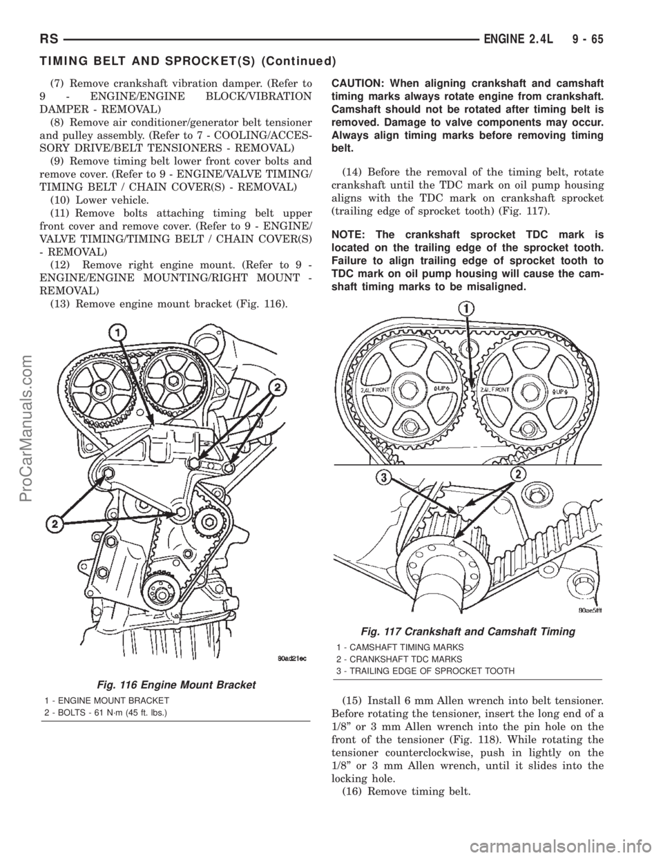
(13) Remove engine mount bracket (Fig. 116).CAUTION: When aligning crankshaft and camshaft
timing marks always rotate engine from crankshaft.
Camshaft should not be rotated after timing belt is
removed. Damage to valve components may occur.
Always align timing marks before removing timing
belt.
(14) Before the removal of the timing belt, rotate
crankshaft until the TDC mark on oil pump housing
aligns with the TDC mark on crankshaft sprocket
(trailing edge of sprocket tooth) (Fig. 117).
NOTE: The crankshaft sprocket TDC mark is
located on the trailing edge of the sprocket tooth.
Failure to align trailing edge of sprocket tooth to
TDC mark on oil pump housing will cause the cam-
shaft timing marks to be misaligned.
(15) Install 6 mm Allen wrench into belt tensioner.
Before rotating the tensioner, insert the long end of a
1/8º or 3 mm Allen wrench into the pin hole on the
front of the tensioner (Fig. 118). While rotating the
tensioner counterclockwise, push in lightly on the
1/8º or 3 mm Allen wrench, until it slides into the
locking hole.
(16) Remove timing belt.
Fig. 116 Engine Mount Bracket
1 - ENGINE MOUNT BRACKET
2 - BOLTS - 61 N´m (45 ft. lbs.)
Fig. 117 Crankshaft and Camshaft Timing
1 - CAMSHAFT TIMING MARKS
2 - CRANKSHAFT TDC MARKS
3 - TRAILING EDGE OF SPROCKET TOOTH
RSENGINE 2.4L9-65
TIMING BELT AND SPROCKET(S) (Continued)
ProCarManuals.com
Page 1269 of 2399
(5) Remove the pull pin or Allen wrench from the
belt tensioner.
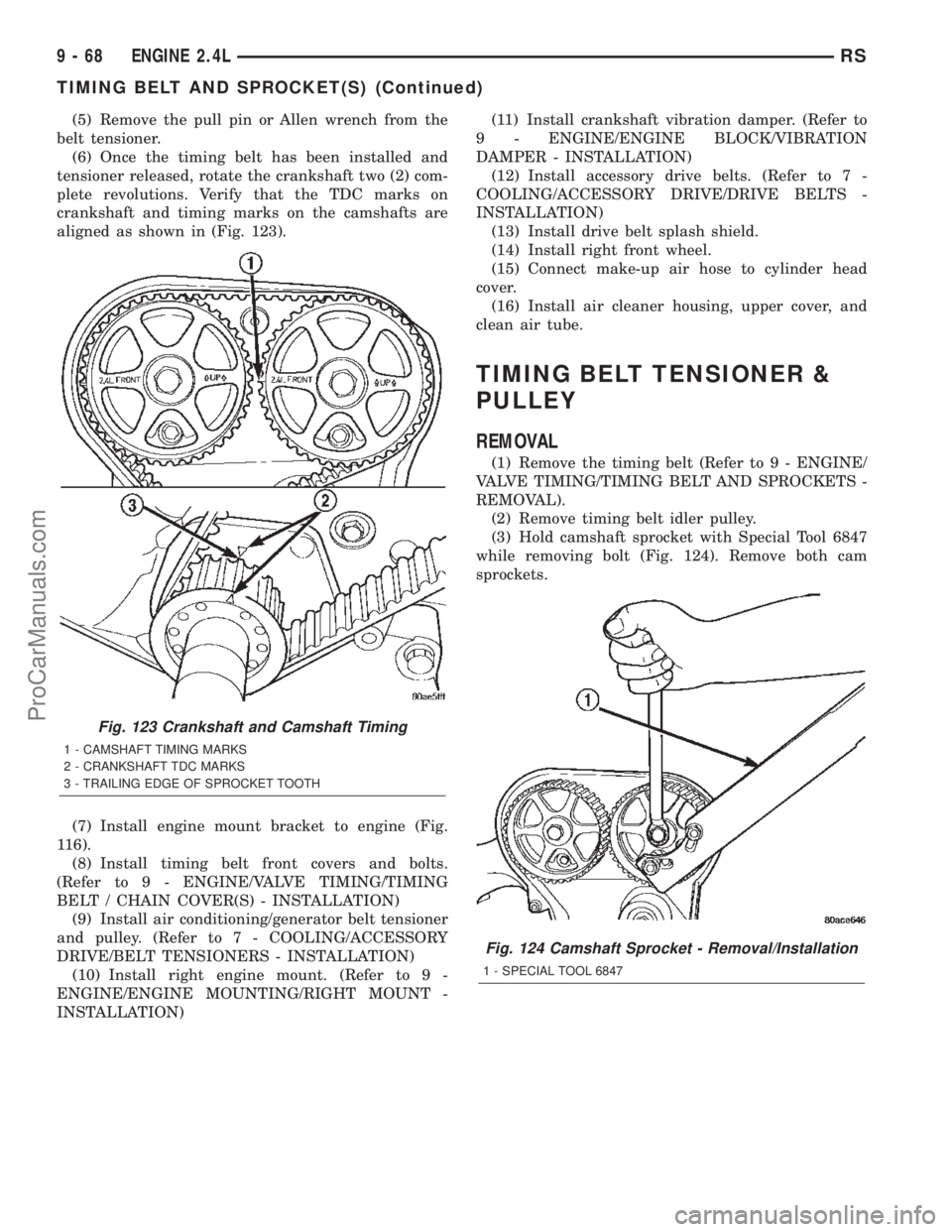
(6) Once the timing belt has been installed and
tensioner released, rotate the crankshaft two (2) com-
plete revolutions. Verify that the TDC marks on
crankshaft and timing marks on the camshafts are
aligned as shown in (Fig. 123).
(7) Install engine mount bracket to engine (Fig.
116).
(8) Install timing belt front covers and bolts.
(Refer to 9 - ENGINE/VALVE TIMING/TIMING
BELT / CHAIN COVER(S) - INSTALLATION)
(9) Install air conditioning/generator belt tensioner
and pulley. (Refer to 7 - COOLING/ACCESSORY
DRIVE/BELT TENSIONERS - INSTALLATION)
(10) Install right engine mount. (Refer to 9 -
ENGINE/ENGINE MOUNTING/RIGHT MOUNT -
INSTALLATION)(11) Install crankshaft vibration damper. (Refer to
9 - ENGINE/ENGINE BLOCK/VIBRATION
DAMPER - INSTALLATION)
(12) Install accessory drive belts. (Refer to 7 -
COOLING/ACCESSORY DRIVE/DRIVE BELTS -
INSTALLATION)
(13) Install drive belt splash shield.
(14) Install right front wheel.
(15) Connect make-up air hose to cylinder head
cover.
(16) Install air cleaner housing, upper cover, and
clean air tube.
TIMING BELT TENSIONER &
PULLEY
REMOVAL
(1) Remove the timing belt (Refer to 9 - ENGINE/
VALVE TIMING/TIMING BELT AND SPROCKETS -
REMOVAL).
(2) Remove timing belt idler pulley.
(3) Hold camshaft sprocket with Special Tool 6847
while removing bolt (Fig. 124). Remove both cam
sprockets.
Fig. 123 Crankshaft and Camshaft Timing
1 - CAMSHAFT TIMING MARKS
2 - CRANKSHAFT TDC MARKS
3 - TRAILING EDGE OF SPROCKET TOOTH
Fig. 124 Camshaft Sprocket - Removal/Installation
1 - SPECIAL TOOL 6847
9 - 68 ENGINE 2.4LRS
TIMING BELT AND SPROCKET(S) (Continued)
ProCarManuals.com