CHRYSLER VOYAGER 1996 Service Manual
Manufacturer: CHRYSLER, Model Year: 1996, Model line: VOYAGER, Model: CHRYSLER VOYAGER 1996Pages: 1938, PDF Size: 55.84 MB
Page 1461 of 1938
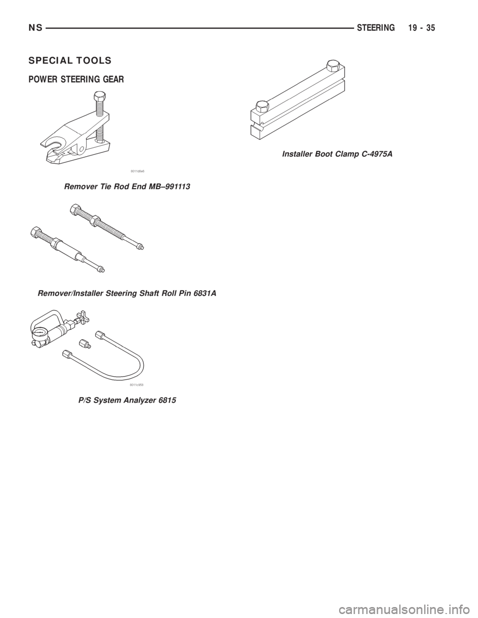
SPECIAL TOOLS
POWER STEERING GEAR
Remover Tie Rod End MB±991113
Remover/Installer Steering Shaft Roll Pin 6831A
P/S System Analyzer 6815
Installer Boot Clamp C-4975A
NSSTEERING 19 - 35
Page 1462 of 1938
STEERING COLUMN
INDEX
page page
DESCRIPTION AND OPERATION
STEERING COLUMN DESCRIPTION......... 36
DIAGNOSIS AND TESTING
STEERING COLUMN..................... 38
SERVICE PROCEDURES
STEERING COLUMN SERVICE PROCEDURE
WARNINGS........................... 38REMOVAL AND INSTALLATION
STEERING COLUMN ASSEMBLY............ 38
SPECIFICATIONS
STEERING COLUMN FASTENER TORQUE
SPECIFICATIONS...................... 45
DESCRIPTION AND OPERATION
STEERING COLUMN DESCRIPTION
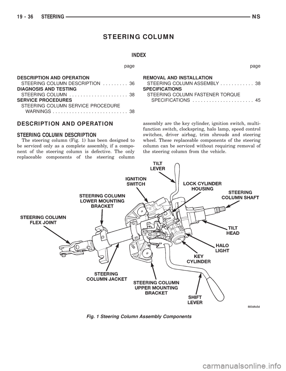
The steering column (Fig. 1) has been designed to
be serviced only as a complete assembly, if a compo-
nent of the steering column is defective. The only
replaceable components of the steering columnassembly are the key cylinder, ignition switch, multi-
function switch, clockspring, halo lamp, speed control
switches, driver airbag, trim shrouds and steering
wheel. These replaceable components of the steering
column can be serviced without requiring removal of
the steering column from the vehicle.
Fig. 1 Steering Column Assembly Components
19 - 36 STEERINGNS
Page 1463 of 1938
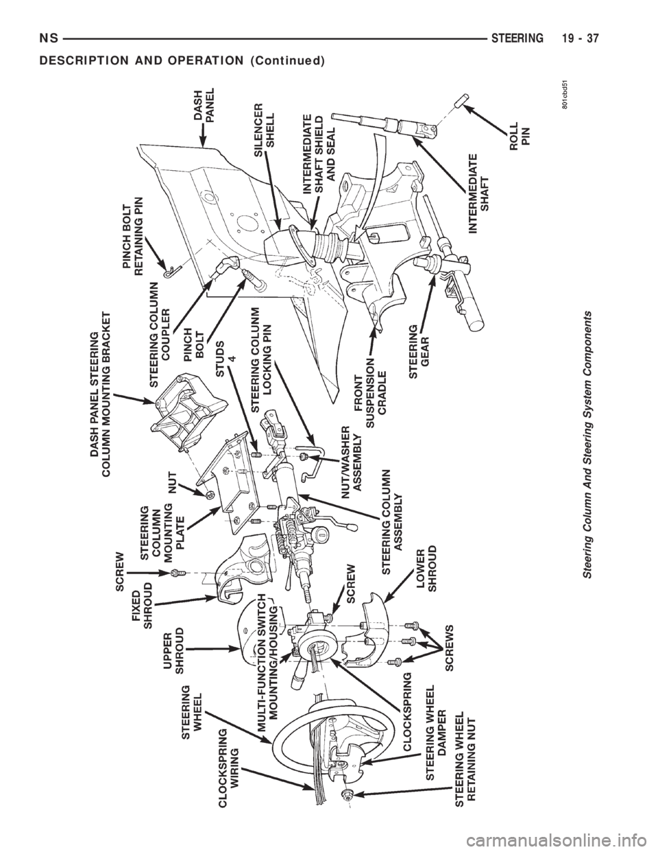
Steering Column And Steering System Components
NSSTEERING 19 - 37
DESCRIPTION AND OPERATION (Continued)
Page 1464 of 1938
DIAGNOSIS AND TESTING
STEERING COLUMN
For diagnosis of conditions relating to the steering
column, refer to the steering system diagnosis charts,
in the diagnosis and testing section at the beginning
of this group.
SERVICE PROCEDURES
STEERING COLUMN SERVICE PROCEDURE
WARNINGS
WARNING: BEFORE BEGINNING ANY SERVICE
PROCEDURES THAT INVOLVES REMOVING THE
AIR BAG. REMOVE AND ISOLATE THE NEGATIVE
(-) BATTERY CABLE (GROUND) FROM THE VEHI-
CLE BATTERY. THIS IS THE ONLY SURE WAY TO
DISABLE THE AIR BAG SYSTEM. FAILURE TO DO
THIS COULD RESULT IN ACCIDENTAL AIR BAG
DEPLOYMENT AND POSSIBLE PERSONAL INJURY.
WARNING: THE AIR BAG SYSTEM IS A SENSITIVE,
COMPLEX ELECTRO-MECHANICAL UNIT. BEFORE
ATTEMPTING TO DIAGNOSE, REMOVE OR INSTALL
THE AIR BAG SYSTEM COMPONENTS YOU MUST
FIRST DISCONNECT AND ISOLATE THE BATTERY
NEGATIVE (GROUND) CABLE. FAILURE TO DO SO
COULD RESULT IN ACCIDENTAL DEPLOYMENT OF
THE AIR BAG AND POSSIBLE PERSONAL INJURY.
THE FASTENERS, SCREWS, AND BOLTS, ORIGI-
NALLY USED FOR THE AIR BAG COMPONENTS,
HAVE SPECIAL COATINGS AND ARE SPECIFI-
CALLY DESIGNED FOR THE AIR BAG SYSTEM.
THEY MUST NEVER BE REPLACED WITH ANY SUB-
STITUTES. ANYTIME A NEW FASTENER IS
NEEDED, REPLACE WITH THE CORRECT FASTEN-
ERS PROVIDED IN THE SERVICE PACKAGE OR
FASTENERS LISTED IN THE PARTS BOOKS.
BEFORE SERVICING A STEERING COLUMN
EQUIPPED WITH AN AIR BAG, REFER TO GROUP
8M, ELECTRICAL FOR PROPER AND SAFE SER-
VICE PROCEDURES.
NOTE: Safety goggles should be worn at all times
when working on steering columns.
CAUTION: Disconnect negative (ground) cable
from the battery, before servicing any column com-
ponent.CAUTION: Do not attempt to remove the pivot pins
to disassemble the tilting mechanism. Damage will
occur.
REMOVAL AND INSTALLATION
STEERING COLUMN ASSEMBLY
To service the steering wheel and its components
or the air bag, refer to Group 8M, Restraint Systems.
Follow all WARNINGS.
To service the switches, refer to the appropriate
section of Group 8, Electrical.
To replace the steering column assembly, refer to
the steering column removal procedure.
REMOVE
(1) Make sure the front wheels of the vehicle are
in thestraight aheadposition before beginning the
column removal procedure.
(2) Disconnect negative (ground) cable from the
battery and isolate cable from battery terminal.
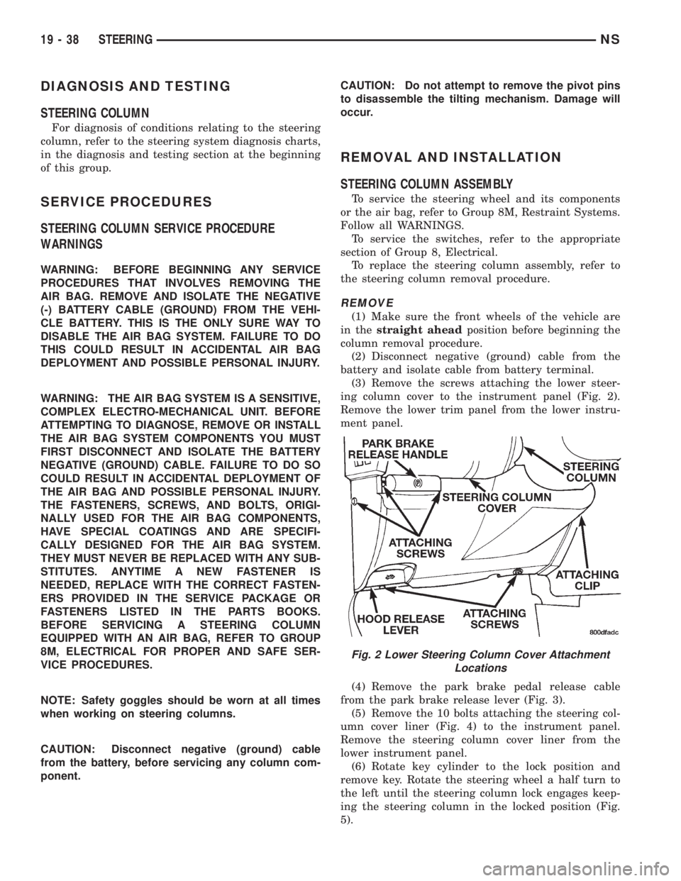
(3) Remove the screws attaching the lower steer-
ing column cover to the instrument panel (Fig. 2).
Remove the lower trim panel from the lower instru-
ment panel.
(4) Remove the park brake pedal release cable
from the park brake release lever (Fig. 3).
(5) Remove the 10 bolts attaching the steering col-
umn cover liner (Fig. 4) to the instrument panel.
Remove the steering column cover liner from the
lower instrument panel.
(6) Rotate key cylinder to the lock position and
remove key. Rotate the steering wheel a half turn to
the left until the steering column lock engages keep-
ing the steering column in the locked position (Fig.
5).
Fig. 2 Lower Steering Column Cover Attachment
Locations
19 - 38 STEERINGNS
Page 1465 of 1938
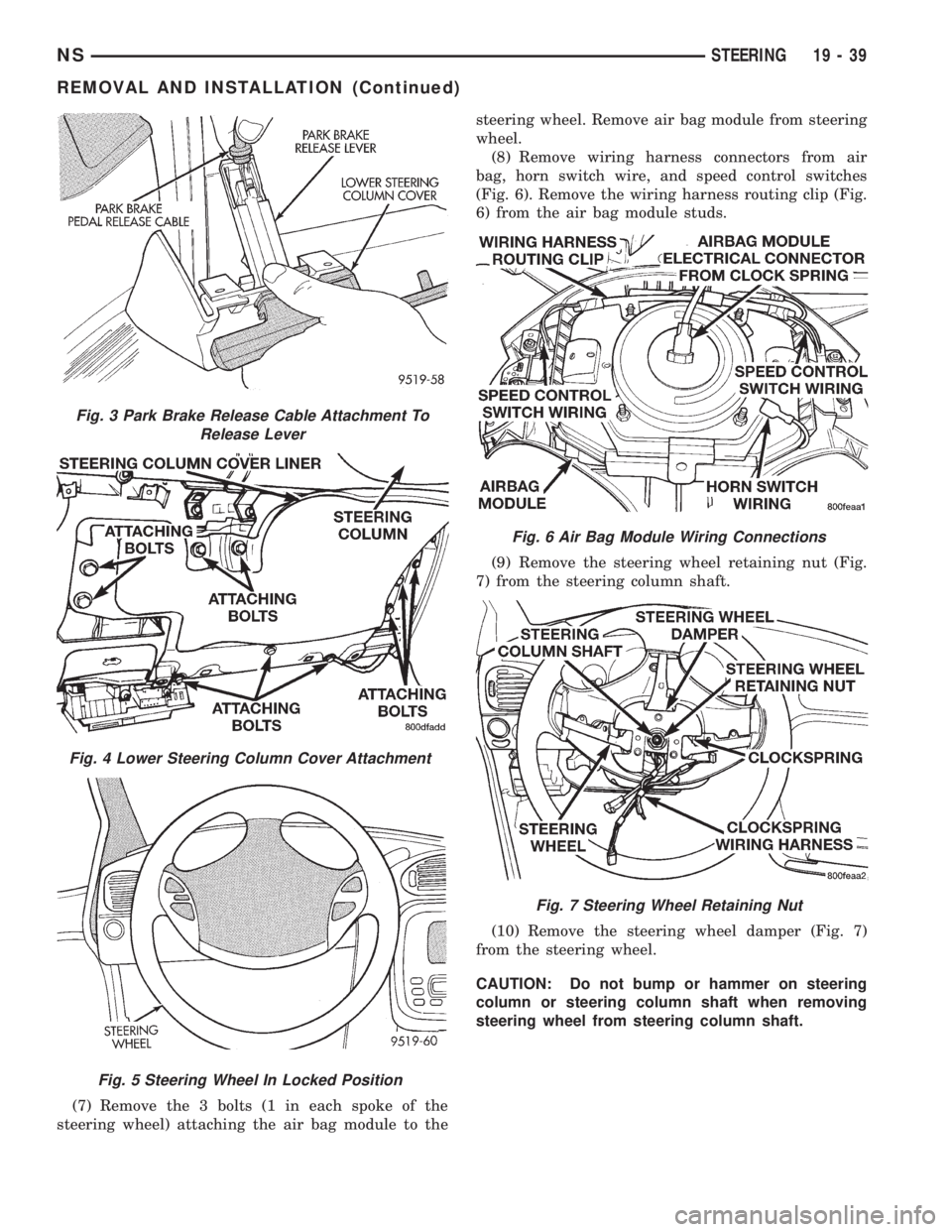
(7) Remove the 3 bolts (1 in each spoke of the
steering wheel) attaching the air bag module to thesteering wheel. Remove air bag module from steering
wheel.
(8) Remove wiring harness connectors from air
bag, horn switch wire, and speed control switches
(Fig. 6). Remove the wiring harness routing clip (Fig.
6) from the air bag module studs.
(9) Remove the steering wheel retaining nut (Fig.
7) from the steering column shaft.
(10) Remove the steering wheel damper (Fig. 7)
from the steering wheel.
CAUTION: Do not bump or hammer on steering
column or steering column shaft when removing
steering wheel from steering column shaft.
Fig. 3 Park Brake Release Cable Attachment To
Release Lever
Fig. 4 Lower Steering Column Cover Attachment
Fig. 5 Steering Wheel In Locked Position
Fig. 6 Air Bag Module Wiring Connections
Fig. 7 Steering Wheel Retaining Nut
NSSTEERING 19 - 39
REMOVAL AND INSTALLATION (Continued)
Page 1466 of 1938
CAUTION: When installing steering wheel puller
bolts in steering wheel, (Fig. 8) do not thread bolt
into steering wheel more than a half inch. If bolts
are threaded into the steering wheel more than a
half inch they will contact and damage the clock-
spring.
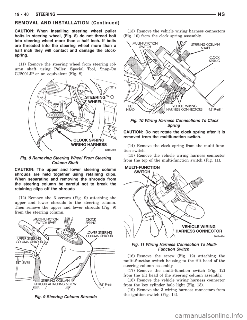
(11) Remove the steering wheel from steering col-
umn shaft using Puller, Special Tool, Snap-On
CJ2001JP or an equivalent (Fig. 8).
CAUTION: The upper and lower steering column
shrouds are held together using retaining clips.
When separating and removing the shrouds from
the steering column be careful not to break the
retaining clips off the shrouds
(12) Remove the 3 screws (Fig. 9) attaching the
upper and lower shrouds to the steering column.
Then remove the upper and lower shrouds (Fig. 9)
from the steering column.(13) Remove the vehicle wiring harness connectors
(Fig. 10) from the clock spring assembly.
CAUTION: Do not rotate the clock spring after it is
removed from the multifunction switch.
(14) Remove the clock spring from the multi-func-
tion switch.
(15) Remove the vehicle wiring harness connector
from the top of the multi-function switch (Fig. 11).
(16) Remove the screw (Fig. 12) attaching the
multi-function switch housing to the tilt head of the
steering column assembly.
(17) Remove the multi-function switch (Fig. 12)
from the tilt head of the steering column assembly.
(18) Remove the vehicle wiring harness connector
from the key cylinder halo light (Fig. 13).
(19) Remove the 3 wiring harness connectors from
the ignition switch (Fig. 14).
Fig. 8 Removing Steering Wheel From Steering
Column Shaft
Fig. 9 Steering Column Shrouds
Fig. 10 Wiring Harness Connections To Clock
Spring
Fig. 11 Wiring Harness Connection To Multi-
Function Switch
19 - 40 STEERINGNS
REMOVAL AND INSTALLATION (Continued)
Page 1467 of 1938
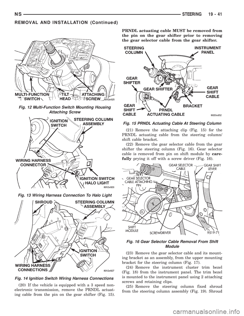
(20) If the vehicle is equipped with a 3 speed non-
electronic transmission, remove the PRNDL actuat-
ing cable from the pin on the gear shifter (Fig. 15).PRNDL actuating cable MUST be removed from
the pin on the gear shifter prior to removing
the gear selector cable from the gear shifter.
(21) Remove the attaching clip (Fig. 15) for the
PRNDL actuating cable from the steering column/
shift cable bracket.
(22) Remove the gear selector cable from the gear
shifter the steering column (Fig. 16). Gear selector
cable is removed from pin on shift module bycare-
fullyprying it off with a screw driver (Fig. 16).
(23) Remove the gear selector cable and its mount-
ing bracket as an assembly, from the upper mounting
bracket for the steering column (Fig. 17).
(24) Remove the instrument cluster trim bezel
(Fig. 18) from the instrument panel. The trim bezel
is mounted to the instrument panel using 2 attaching
screws and retaining clips.
(25) Remove the steering column fixed shroud
from the steering column assembly (Fig. 19). Shroud
Fig. 12 Multi-Function Switch Mounting Housing
Attaching Screw
Fig. 13 Wiring Harness Connection To Halo Light
Fig. 14 Ignition Switch Wiring Harness Connections
Fig. 15 PRNDL Actuating Cable At Steering Column
Fig. 16 Gear Selector Cable Removal From Shift
Module
NSSTEERING 19 - 41
REMOVAL AND INSTALLATION (Continued)
Page 1468 of 1938
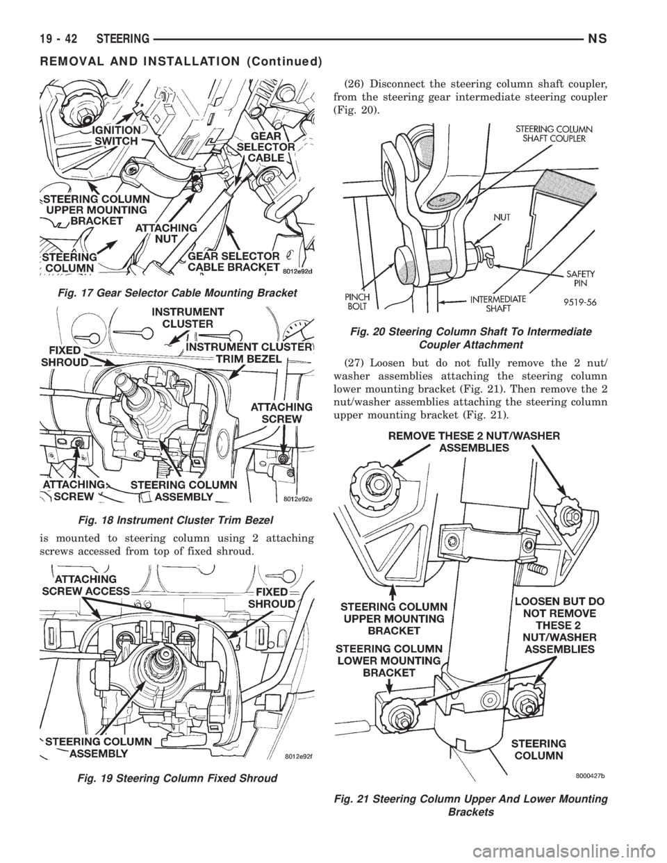
is mounted to steering column using 2 attaching
screws accessed from top of fixed shroud.(26) Disconnect the steering column shaft coupler,
from the steering gear intermediate steering coupler
(Fig. 20).
(27) Loosen but do not fully remove the 2 nut/
washer assemblies attaching the steering column
lower mounting bracket (Fig. 21). Then remove the 2
nut/washer assemblies attaching the steering column
upper mounting bracket (Fig. 21).
Fig. 17 Gear Selector Cable Mounting Bracket
Fig. 18 Instrument Cluster Trim Bezel
Fig. 19 Steering Column Fixed Shroud
Fig. 20 Steering Column Shaft To Intermediate
Coupler Attachment
Fig. 21 Steering Column Upper And Lower Mounting
Brackets
19 - 42 STEERINGNS
REMOVAL AND INSTALLATION (Continued)
Page 1469 of 1938
(28) Remove steering column assembly from vehi-
cle. Use care to avoid damage to paint or interior
trim.
INSTALL
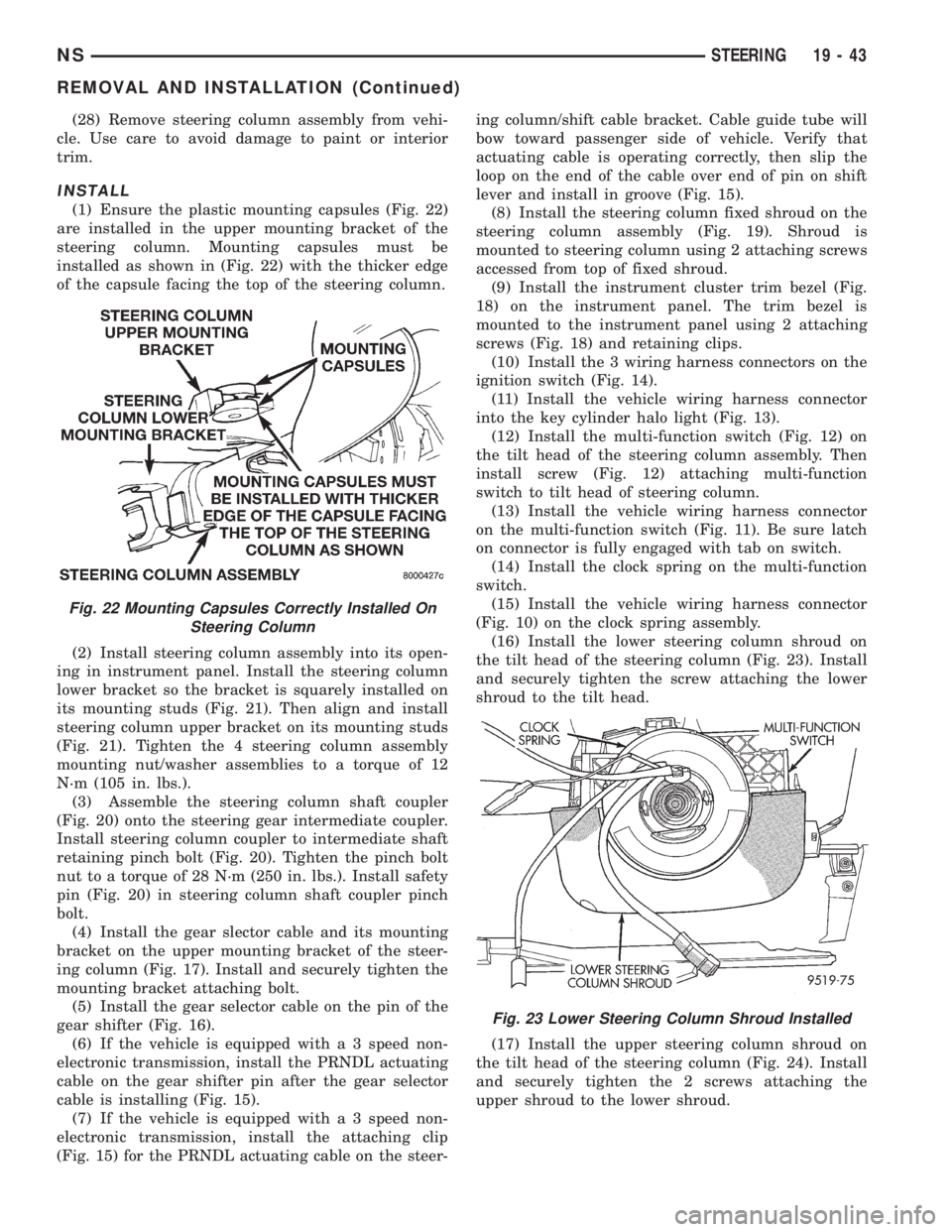
(1) Ensure the plastic mounting capsules (Fig. 22)
are installed in the upper mounting bracket of the
steering column. Mounting capsules must be
installed as shown in (Fig. 22) with the thicker edge
of the capsule facing the top of the steering column.
(2) Install steering column assembly into its open-
ing in instrument panel. Install the steering column
lower bracket so the bracket is squarely installed on
its mounting studs (Fig. 21). Then align and install
steering column upper bracket on its mounting studs
(Fig. 21). Tighten the 4 steering column assembly
mounting nut/washer assemblies to a torque of 12
N´m (105 in. lbs.).
(3) Assemble the steering column shaft coupler
(Fig. 20) onto the steering gear intermediate coupler.
Install steering column coupler to intermediate shaft
retaining pinch bolt (Fig. 20). Tighten the pinch bolt
nut to a torque of 28 N´m (250 in. lbs.). Install safety
pin (Fig. 20) in steering column shaft coupler pinch
bolt.
(4) Install the gear slector cable and its mounting
bracket on the upper mounting bracket of the steer-
ing column (Fig. 17). Install and securely tighten the
mounting bracket attaching bolt.
(5) Install the gear selector cable on the pin of the
gear shifter (Fig. 16).
(6) If the vehicle is equipped with a 3 speed non-
electronic transmission, install the PRNDL actuating
cable on the gear shifter pin after the gear selector
cable is installing (Fig. 15).
(7) If the vehicle is equipped with a 3 speed non-
electronic transmission, install the attaching clip
(Fig. 15) for the PRNDL actuating cable on the steer-ing column/shift cable bracket. Cable guide tube will
bow toward passenger side of vehicle. Verify that
actuating cable is operating correctly, then slip the
loop on the end of the cable over end of pin on shift
lever and install in groove (Fig. 15).
(8) Install the steering column fixed shroud on the
steering column assembly (Fig. 19). Shroud is
mounted to steering column using 2 attaching screws
accessed from top of fixed shroud.
(9) Install the instrument cluster trim bezel (Fig.
18) on the instrument panel. The trim bezel is
mounted to the instrument panel using 2 attaching
screws (Fig. 18) and retaining clips.
(10) Install the 3 wiring harness connectors on the
ignition switch (Fig. 14).
(11) Install the vehicle wiring harness connector
into the key cylinder halo light (Fig. 13).
(12) Install the multi-function switch (Fig. 12) on
the tilt head of the steering column assembly. Then
install screw (Fig. 12) attaching multi-function
switch to tilt head of steering column.
(13) Install the vehicle wiring harness connector
on the multi-function switch (Fig. 11). Be sure latch
on connector is fully engaged with tab on switch.
(14) Install the clock spring on the multi-function
switch.
(15) Install the vehicle wiring harness connector
(Fig. 10) on the clock spring assembly.
(16) Install the lower steering column shroud on
the tilt head of the steering column (Fig. 23). Install
and securely tighten the screw attaching the lower
shroud to the tilt head.
(17) Install the upper steering column shroud on
the tilt head of the steering column (Fig. 24). Install
and securely tighten the 2 screws attaching the
upper shroud to the lower shroud.
Fig. 22 Mounting Capsules Correctly Installed On
Steering Column
Fig. 23 Lower Steering Column Shroud Installed
NSSTEERING 19 - 43
REMOVAL AND INSTALLATION (Continued)
Page 1470 of 1938
CAUTION: Before installing the steering wheel the
clockspring must be centered. If clockspring is not
centered, the wiring in the clockspring may be over-
extended and break when the steering wheel is
rotated. Use the following procedure to center the
clockspring.
CLOCKSPRING CENTERING PROCEDURE
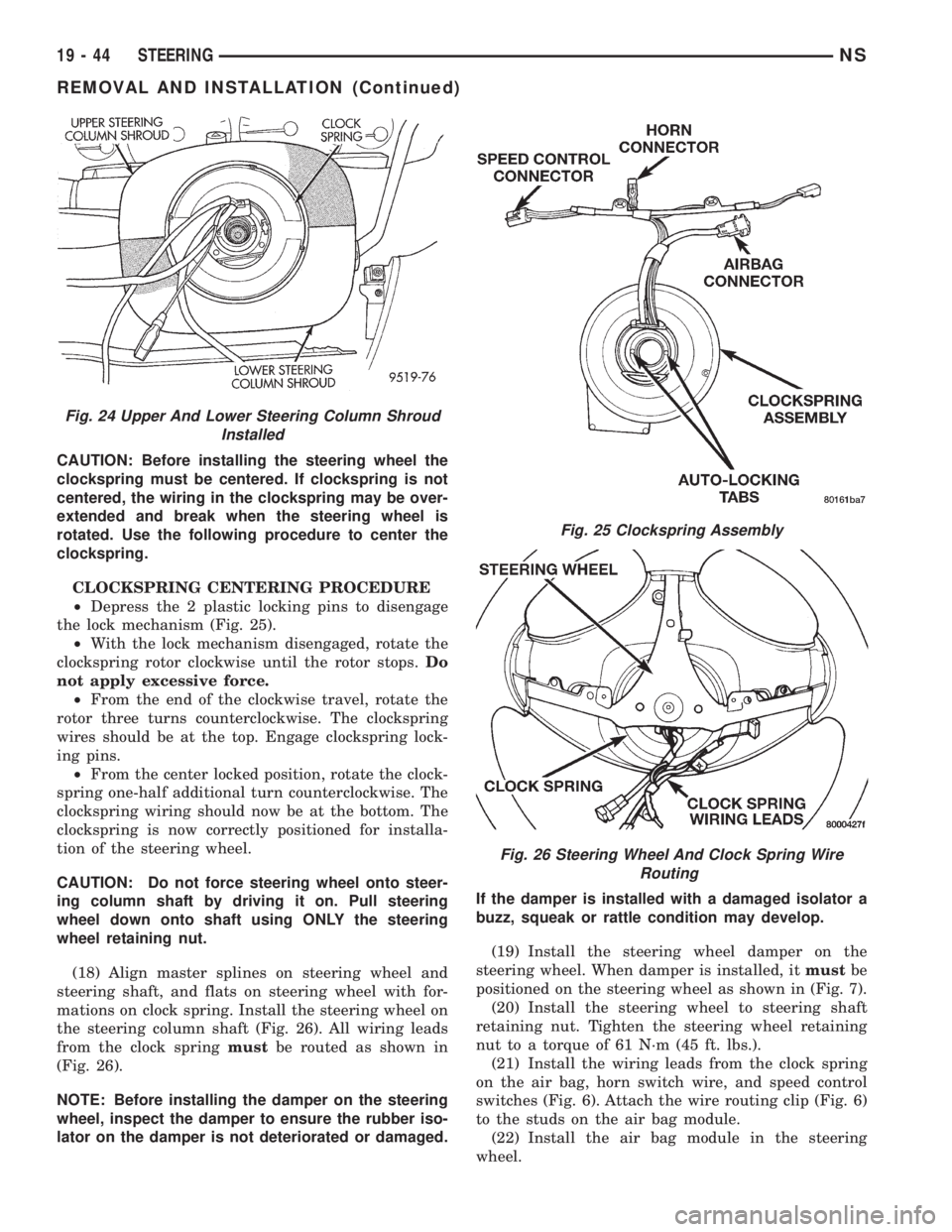
²Depress the 2 plastic locking pins to disengage
the lock mechanism (Fig. 25).
²With the lock mechanism disengaged, rotate the
clockspring rotor clockwise until the rotor stops.Do
not apply excessive force.
²From the end of the clockwise travel, rotate the
rotor three turns counterclockwise. The clockspring
wires should be at the top. Engage clockspring lock-
ing pins.
²From the center locked position, rotate the clock-
spring one-half additional turn counterclockwise. The
clockspring wiring should now be at the bottom. The
clockspring is now correctly positioned for installa-
tion of the steering wheel.
CAUTION: Do not force steering wheel onto steer-
ing column shaft by driving it on. Pull steering
wheel down onto shaft using ONLY the steering
wheel retaining nut.
(18) Align master splines on steering wheel and
steering shaft, and flats on steering wheel with for-
mations on clock spring. Install the steering wheel on
the steering column shaft (Fig. 26). All wiring leads
from the clock springmustbe routed as shown in
(Fig. 26).
NOTE: Before installing the damper on the steering
wheel, inspect the damper to ensure the rubber iso-
lator on the damper is not deteriorated or damaged.If the damper is installed with a damaged isolator a
buzz, squeak or rattle condition may develop.
(19) Install the steering wheel damper on the
steering wheel. When damper is installed, itmustbe
positioned on the steering wheel as shown in (Fig. 7).
(20) Install the steering wheel to steering shaft
retaining nut. Tighten the steering wheel retaining
nut to a torque of 61 N´m (45 ft. lbs.).
(21) Install the wiring leads from the clock spring
on the air bag, horn switch wire, and speed control
switches (Fig. 6). Attach the wire routing clip (Fig. 6)
to the studs on the air bag module.
(22) Install the air bag module in the steering
wheel.
Fig. 24 Upper And Lower Steering Column Shroud
Installed
Fig. 25 Clockspring Assembly
Fig. 26 Steering Wheel And Clock Spring Wire
Routing
19 - 44 STEERINGNS
REMOVAL AND INSTALLATION (Continued)