torque CHRYSLER VOYAGER 1996 Service Manual
[x] Cancel search | Manufacturer: CHRYSLER, Model Year: 1996, Model line: VOYAGER, Model: CHRYSLER VOYAGER 1996Pages: 1938, PDF Size: 55.84 MB
Page 1251 of 1938
NOTE: Inspect O-ring in flywheel (Fig. 67).
(3) Remove rear crankshaft oil seal from retainer
(Fig. 68).
CAUTION: When removing seal from retainer take
care not to damage retainer.
INSTALLATION
(1) Install crankshaft oil seal.
CAUTION: Use NEW flywheel bolt for the following
procedure.
(2) Install new O-ring on flywheel. Install fly-
wheel. The 6 flywheel bolts must be tightened as fol-
lows:
a. Torque the 6 flywheel bolts to 60 N´m (44 ft.
lbs.).b. Loosen 2 of the 6 bolts, 180É apart. Torque the 2
bolts to 20 N´m (180 in. lbs.). Then using a torque
angle gauge rotate the 2 bolts 65É additional.
c. Loosen the next 2 bolts, 180É apart and follow
the same procedure.
d. Loosen the last 2 bolts, 180É apart and follow
the same procedure.
(3) Install Transmission. Refer to procedure in
Group 21, Transmission.
DISASSEMBLY AND ASSEMBLY
HYDRAULIC TAPPETS
DISASSEMBLE AND ASSEMBLE
(1) Pry out plunger retainer spring clip.
(2) Clean varnish deposits from inside of tappet
body above plunger cap.
(3) Invert tappet body and remove plunger cap,
plunger, check valve, check valve spring, check valve
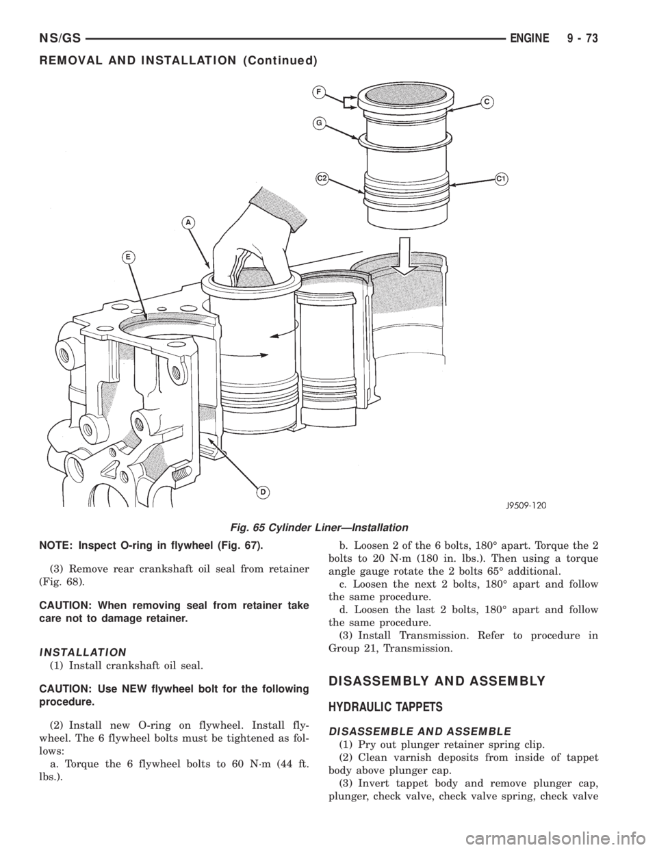
Fig. 65 Cylinder LinerÐInstallation
NS/GSENGINE 9 - 73
REMOVAL AND INSTALLATION (Continued)
Page 1255 of 1938
(3.6196-3.6200 in.). Maximum wear limit .05mm
(.0019 in.).
(2) Check piston pin bores in piston for roundness.
Make 3 checks at 120É intervals. Maximum out of
roundness .05mm (.0019in.).
(3) The piston diameter should be measured
approximately 15 mm (.590 in.) up from the base.
(4) Skirt wear should not exceed 0.1 mm (.00039
in.).
(5) The clearance between the cylinder liner and
piston should not exceed 0.25 mm (.0009 in.).
(6) Make sure the weight of the pistons does not
differ by more than 5 g.
CONNECTING ROD
(1) Assemble bearing shells and bearing caps to
their respective connecting rods ensuring that the
serrations on the cap and reference marks are
aligned.
(2) Tighten bearing cap bolts to 29 N´m (21 ft. lbs.)
plus 60É.
(3) Check and record internal diameter of crank
end of connecting rod.
Note: When changing connecting rods, all four
must have the same weight and be stamped with the
same number.Replacement connecting rods will
only be supplied in sets of four.
(4) Connecting rods are supplied in sets of four
since they all must be of the same weight category.
Max allowable weight difference is 18 gr.NOTE:On
one side of the big end of the con-rod there is a two-
digit number which refers to the weight category. On
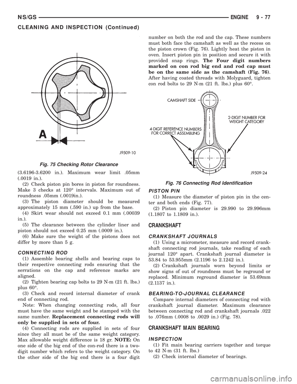
the other side of the big end there is a four digitnumber on both the rod and the cap. These numbers
must both face the camshaft as well as the recess on
the piston crown (Fig. 76). Lightly heat the piston in
oven. Insert piston pin in position and secure it with
provided snap rings.The Four digit numbers
marked on con rod big end and rod cap must
be on the same side as the camshaft (Fig. 76).
After having coated threads with Molyguard, tighten
con rod bolts to 29 N´m (21 ft. lbs.) plus 60É.
PISTON PIN
(1) Measure the diameter of piston pin in the cen-
ter and both ends (Fig. 77).
(2) Piston pin diameter is 29.990 to 29.996mm
(1.1807 to 1.1809 in.).
CRANKSHAFT
CRANKSHAFT JOURNALS
(1) Using a micrometer, measure and record crank-
shaft connecting rod journals, take reading of each
journal 120É apart. Crankshaft journal diameter is
53.84 to 53.955mm (2.1196 to 2.1242 in.).
(2) Crankshaft journals worn beyond limits or
show signs of out of roundness must be reground or
replaced. Minimum reground diameter is 53.69mm
(2.1137 in.).
BEARING-TO-JOURNAL CLEARANCE
Compare internal diameters of connecting rod with
crankshaft journal diameter. Maximum clearance
between connecting rod and crankshaft journals .022
to .076mm (.0008 to .0029 in.) (Fig. 78).
CRANKSHAFT MAIN BEARING
INSPECTION
(1) Fit main bearing carriers together and torque
to 42 N´m (31 ft. lbs.)
(2) Check internal diameter of bearings.
Fig. 75 Checking Rotor Clearance
Fig. 76 Connecting Rod Identification
NS/GSENGINE 9 - 77
CLEANING AND INSPECTION (Continued)
Page 1258 of 1938
DESCRIPTION...........SPECIFICATIONS
Valve Face Angle
Intake.......................55É30'± 55É50'
Exhaust.....................45É25'± 45É35'
Valve Head Diameter
Intake.....................40.05±40.25 mm
Exhaust.....................33.8±34.0 mm
Valve Head Stand Down
Intake.......................1.08±1.34 mm
Exhaust.....................1.99±1.25 mm
Valve Stem Diameter
Intake.....................7.940±7.960 mm
Exhaust....................7.922±7.940 mm
Valve Clearance in Guide
Intake.....................0.040±0.075 mm
Exhaust....................0.060±0.093 mm
Valve Guide
Inside Diameter...............8.0±8.015 mm
Fitted Height.................13.5±14.0 mm
Valve Spring
Free Length.....................44.65 mm
Fitted Length.....................38.6 mm
Load at Fitted Length............3466% Kg
Load at Top of Lift.............92.564% Kg
Number of Coils............5.33 Valve Timing
Oil Pressure
at 4000 rpm.....3.0to4.5bar(Oil at 90±100ÉC)
Pressure Relief Valve Opens..........6.38 bar
Pressure Relief Valve±Free Length.....57.5 mm
Oil Pump
Outer Rotor End Float..........0.03±0.09 mm
Inner Rotor End Float..........0.03±0.09 mm
Outer Rotor to Body Diameter
Clearance..................0.130±0.230 mm
Rotor Body to Drive Gear Clearance (Pump Not
Fitted)......................3.27±3.73 mm
TORQUE
DESCRIPTION...................TORQUE
Generator Mounting Bracket
Bolts....................47N´m(35ft.lbs.)
Camshaft Thrust Plate Retaining Bolts
Bolt.....................24N´m(18ft.lbs.)
Cylinder Head
Bolts . . See Cylinder Head Installation Procedure
Connecting Rod
Bolts...........29.5 N´m +60É (22 ft. lbs. +60É)
Crankshaft Bearing Carrier
Bolts....................44N´m(32ft.lbs.)
Crankshaft damper (Pulley)
Nut ...................441N´m(325 ft. lbs.)
EGR Valve to Intake Manifold
Tube ....................26N´m(19ft.lbs.)DESCRIPTION...................TORQUE
EGR Tube to EGR Valve
Bolts....................26N´m(19ft.lbs.)
Engine MountÐFront
Support Bracket Engine Bolts . 68 N´m (50 ft. lbs.)
Support Bracket Transmission
Bolts...................101N´m(75ft.lbs.)
Support Cushion Crossmember
Bolts....................54N´m(40ft.lbs.)
Support Cushion Thru Bolt . . . 65 N´m (48 ft. lbs.)
Engine MountÐRear
Support Bracket Transmission
Bolts...................101N´m(75ft.lbs.)
Support Bracket to Engine
Bracket.................101N´m(75ft.lbs.)
Support Cushion Thru Bolt . . . 68 N´m (50 ft. lbs.)
Engine MountÐLeft
Transmission Mounting Bolts . 54 N´m (40 ft. lbs.)
Support Cushion Thru Bolt . . . 71 N´m (53 ft. lbs.)
Engine MountÐRight
Mount to Frame Rail Bolts . . . 68 N´m (50 ft. lbs.)
Mount Bolt (Horizontal) . . . 145 N´m (107 ft. lbs.)
Mount Bolt (Vertical).......101N´m(75ft.lbs.)
Right Engine Mount Bracket
Bolts....................40N´m(30ft.lbs.)
Exhaust Pipe to Turbocharger
Bolts...................28N´m(250 in. lbs.)
Exhaust Manifold Outlet to Turbo
Nuts....................32N´m(24ft.lbs.)
Exhaust Elbow to Turbo
Bolts....................30N´m(22ft.lbs.)
Exhaust Manifold Mounting
Nuts....................30N´m(22ft.lbs.)
Flywheel
Bolts.....SeeRear Crankshaft Seal Installation
Procedure
Engine Adaptor Plate
Bolts....................47N´m(35ft.lbs.)
Front Timing Gear Cover
Bolts....................11N´m(96in.lbs.)
Fuel Filter
Nuts...................28N´m(250 in. lbs.)
Glow Plugs
Plugs..................14N´m(120 in. lbs.)
Idler Pulley Pump Support Bracket
Nuts...................26N´m(228 in. lbs.)
Idler Pulleys (left handed threads)
Bolts....................47N´m(35ft.lbs.)
Injector Pump fuel lines
Nuts..................17.6 N´m (156 in. lbs.)
Injector Pump Gear
Lock Nut..........................86N´m
Injector Pump Mounting
Nuts..................27.5 N´m (240 in. lbs.)
9 - 80 ENGINENS/GS
SPECIFICATIONS (Continued)
Page 1259 of 1938
DESCRIPTION...................TORQUE
Injector
Tighten to................65N´m(48ft.lbs.)
Intake Manifold Mounting
Nuts...................30N´m(264 in. lbs.)
Main Bearing Oil Delivery Union
Bolts....................54N´m(40ft.lbs.)
Oil Feed Line To Rocker Arms
Bolts.................12.7 N´m (108 in. lbs.)
Oil Feed Line to Block
Bolts.................12.7 N´m (108 in. lbs.)
Oil Feel Line to Vacuum Pump
Bolts.................16.7 N´m (145 in. lbs.)
Oil Filter
Tighten to...............9.8N´m(85in.lbs.)
Oil Filter Adaptor
Fastener.................49N´m(36ft.lbs.)
Oil Filter Base
Fastener.................49N´m(36ft.lbs.)
Oil Pan Mounting
Bolts...................12N´m(108 in. lbs.)
Oil Pickup Tube
Bolts..................11.3N´m(100 in. lbs.)
Oil Pump Mounting
Bolts.................27.5 N´m (240 in. lbs.)
Oil Pan Drain
Plug.....................54N´m(40ft.lbs.)
Power Steering Pressure Hose
Fastener................28N´m(240 in. lbs.)
Power Steering Pulley
Nut ...................170N´m(125 ft. lbs.)
Rear Crankshaft Bearing Carrier
Bolts..................10.8 N´m (95 in. lbs.)
Rocker Arm Cover
Bolts.................14.7 N´m (132 in. lbs.)
Rocker Arm Mounting
Nuts..................29.4 N´m (264 in. lbs.)
Power Steering Pump Mounting
Nuts..................24.5 N´m (216 in. lbs.)
Turbocharger Mounting
Nuts...................32N´m(288 in. lbs.)
Turbocharger Oil Delivery
Bolt..................27.5 N´m (240 in. lbs.)
Turbocharger Oil Drain
Bolts..................10.8 N´m (95 in. lbs.)
Vacuum Pump Mounting
Bolts..................10.8 N´m (95 in. lbs.)
Water Manifold Mounting
Bolts..................11.8N´m(108 in. lbs.)
Water Pump Pulley
Bolts.................27.5 N´m (240 in. lbs.)SPECIAL TOOLS
2.5L VM DIESEL
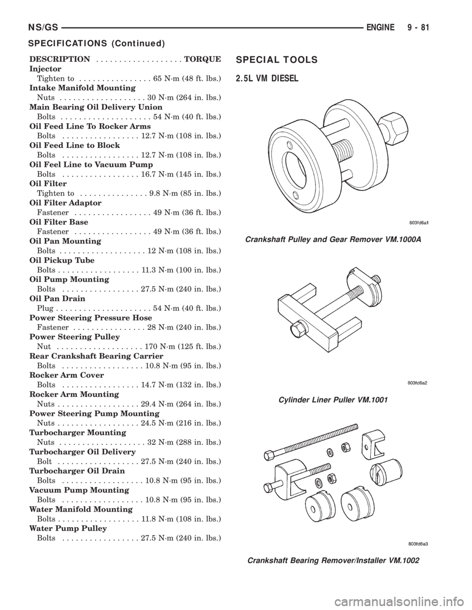
Crankshaft Pulley and Gear Remover VM.1000A
Cylinder Liner Puller VM.1001
Crankshaft Bearing Remover/Installer VM.1002
NS/GSENGINE 9 - 81
SPECIFICATIONS (Continued)
Page 1260 of 1938
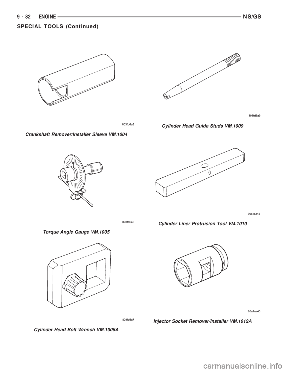
Crankshaft Remover/Installer Sleeve VM.1004
Torque Angle Gauge VM.1005
Cylinder Head Bolt Wrench VM.1006A
Cylinder Head Guide Studs VM.1009
Cylinder Liner Protrusion Tool VM.1010
Injector Socket Remover/Installer VM.1012A
9 - 82 ENGINENS/GS
SPECIAL TOOLS (Continued)
Page 1263 of 1938
EXHAUST SYSTEM AND INTAKE MANIFOLD
CONTENTS
page page
GENERAL INFORMATION
CATALYTIC CONVERTERS................. 1
EXHAUST FLEX-JOINT COUPLING........... 2
EXHAUST GAS RECIRCULATION (EGR)....... 2
EXHAUST SYSTEM....................... 1
HEAT SHIELDS.......................... 2
DESCRIPTION AND OPERATION
INTAKE/EXHAUST MANIFOLDÐ2.4L ENGINE . . 3
INTAKE/EXHAUST MANIFOLDÐ3.0L ENGINE . . 3
INTAKE/EXHAUST MANIFOLDÐ3.3/3.8L
ENGINES............................. 3
DIAGNOSIS AND TESTING
EXHAUST SYSTEM....................... 3REMOVAL AND INSTALLATION
EXHAUST MANIFOLDÐ2.4L ENGINE........ 8
EXHAUST MANIFOLDÐ3.0L ENGINE....... 11
EXHAUST MANIFOLDSÐ3.3/3.8L ENGINE . . . 16
EXHAUST PIPES, MUFFLERS AND TAILPIPES . 4
INTAKE MANIFOLD LOWERÐ2.4L ENGINE.... 6
INTAKE MANIFOLDÐ3.0L ENGINE.......... 8
INTAKE MANIFOLDÐ3.3/3.8L ENGINE...... 12
UPPER INTAKE MANIFOLDÐ2.4L ENGINE.... 4
CLEANING AND INSPECTION
EXHAUST MANIFOLD.................... 17
INTAKE MANIFOLD...................... 17
SPECIFICATIONS
TORQUE CHART........................ 18
GENERAL INFORMATION
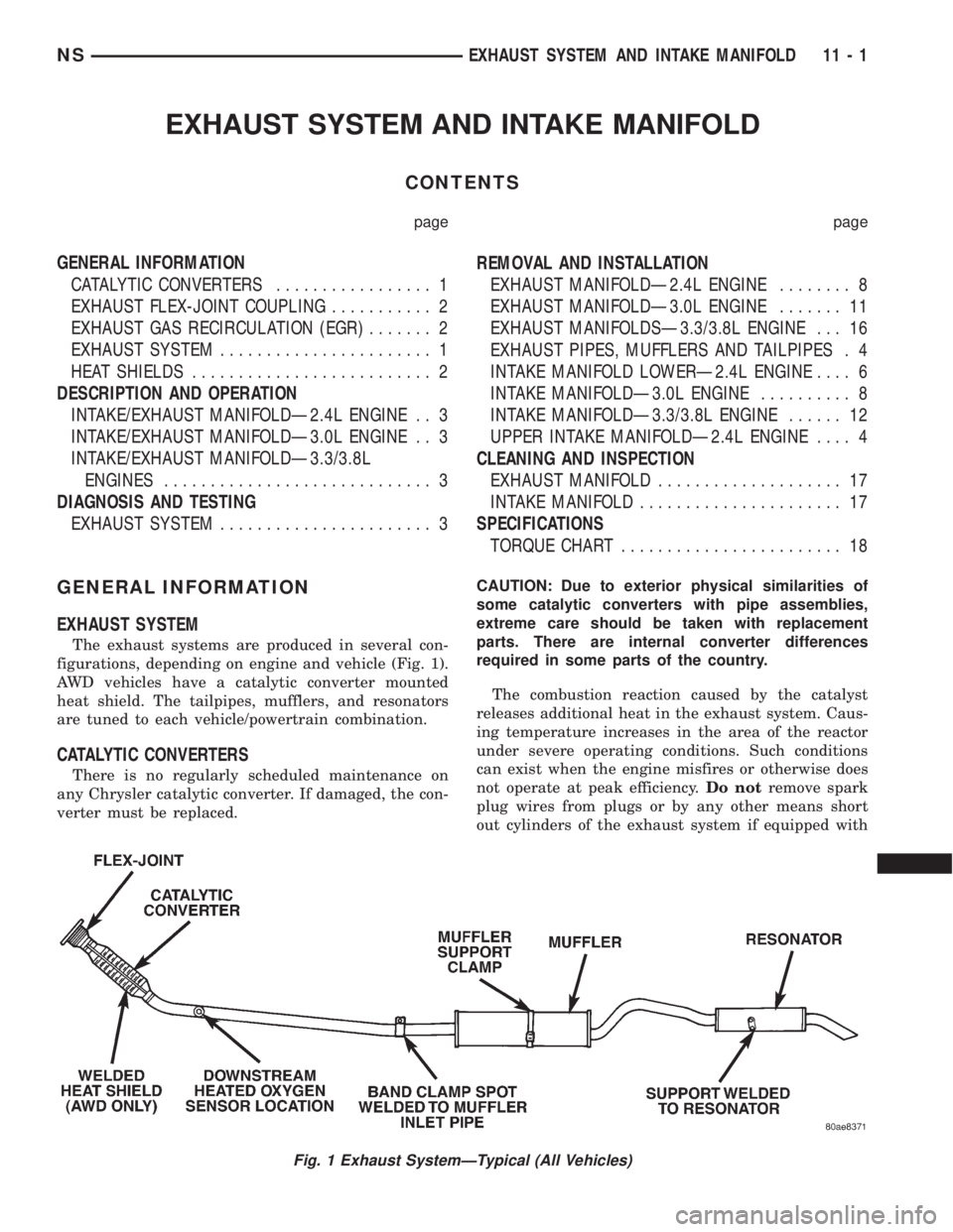
EXHAUST SYSTEM
The exhaust systems are produced in several con-
figurations, depending on engine and vehicle (Fig. 1).
AWD vehicles have a catalytic converter mounted
heat shield. The tailpipes, mufflers, and resonators
are tuned to each vehicle/powertrain combination.
CATALYTIC CONVERTERS
There is no regularly scheduled maintenance on
any Chrysler catalytic converter. If damaged, the con-
verter must be replaced.CAUTION: Due to exterior physical similarities of
some catalytic converters with pipe assemblies,
extreme care should be taken with replacement
parts. There are internal converter differences
required in some parts of the country.
The combustion reaction caused by the catalyst
releases additional heat in the exhaust system. Caus-
ing temperature increases in the area of the reactor
under severe operating conditions. Such conditions
can exist when the engine misfires or otherwise does
not operate at peak efficiency.Do notremove spark
plug wires from plugs or by any other means short
out cylinders of the exhaust system if equipped with
Fig. 1 Exhaust SystemÐTypical (All Vehicles)
NSEXHAUST SYSTEM AND INTAKE MANIFOLD 11 - 1
Page 1265 of 1938
CAUTION: When servicing, care must be exercised
not to dent or bend the bellows of the flex-joint.
Should this occur, the flex-joint will eventually fail
and require the catalytic converter be replaced.
DESCRIPTION AND OPERATION
INTAKE/EXHAUST MANIFOLDÐ2.4L ENGINE
The intake manifold is a tuned two-piece alumi-
num casting with individual primary runners leading
from a plenum to the cylinders. The manifold is
designed to boost torque which is desired for excel-
lent engine response and usable power output.
The exhaust manifold is made of nodular cast iron
for strength and high temperatures.
INTAKE/EXHAUST MANIFOLDÐ3.0L ENGINE
The aluminum alloy manifold is a cross type with
long runners to improve air flow. The runners,
attaching below at the cylinder head, also attach
above and support an air plenum. The air plenum
chamber absorbs air pulsations created during the
suction phase of each cylinder.Both exhaust manifolds are a log style made of
ductile cast iron. Exhaust gasses, collected from the
front cylinder bank, leave the front manifold through
an end outlet and are fed through an upper crossover
tube to the rear manifold. The collected exhaust from
both manifolds are combined at the exhaust outlet, to
the exhaust pipe.
INTAKE/EXHAUST MANIFOLDÐ3.3/3.8L ENGINES
The intake manifold is a tuned two-piece semi-per-
manent mold aluminum casting with individual pri-
mary runners leading from a plenum to the
cylinders. The manifold is designed to boost torque in
the 3600 rpm range and contributes to the engine's
broad, flat torque curve, which was desired for excel-
lent engine tractability, response and usable power
output.
The intake manifold is also cored with upper level
EGR passages for balanced cylinder to cylinder EGR
distribution.
The exhaust manifolds are log type with a cross-
over and are attached directly to the cylinder heads.
They are made from nodular cast iron.
DIAGNOSIS AND TESTING
EXHAUST SYSTEM
CONDITION POSSIBLE CAUSES CORRECTION
EXCESSIVE EXHAUST
NOISE (UNDER HOOD)1. Exhaust manifold cracked or broken. 1. Replace manifold.
2. Manifold to cylinder head leak. 2. Tighten manifold and/or replace gasket.
3. EGR Valve to manifold gasket leakage. 3. Tighten fasteners or replace gasket.
4. EGR Valve to EGR tube gasket
leakage.4. Tighten fasteners or replace gasket.
5. EGR tube to manifold tube leakage. 5. Tighten tube nut.
6. Exhaust flex-joint to manifold leak. 6. Tighten joint fasteners and/or replace
gasket.
7. Exhaust flex-joint. 7. Replace catalytic converter assembly.
8. Pipe and shell noise from front exhaust
pipe.8. Characteristic of single wall pipe.
EXCESSIVE EXHAUST
NOISE1. Leak at exhaust pipe joints. 1. Tighten clamps at leaking joints.
2. Burned or rusted out muffler assembly
or exhaust pipe.2. Replace muffler resonator tailpipe
assembly or exhaust pipe with catalytic
converter assembly.
3. Burned or rusted out resonator. 3. Replace muffler resonator tailpipe
assembly.
4. Restriction in exhaust system. 4. Remove restriction, if possible, or
replace as necessary.
5. Converter material in muffler. 5. Replace muffler and converter
assemblies. Check fuel injection and
ignition systems for proper operation.
NSEXHAUST SYSTEM AND INTAKE MANIFOLD 11 - 3
GENERAL INFORMATION (Continued)
Page 1266 of 1938
REMOVAL AND INSTALLATION
EXHAUST PIPES, MUFFLERS AND TAILPIPES
REMOVAL
(1) Raise vehicle on hoist and apply penetrating
oil to clamp bolts and nuts of component being
removed.
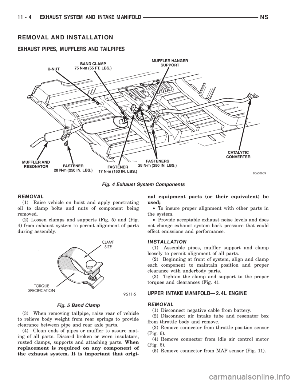
(2) Loosen clamps and supports (Fig. 5) and (Fig.
4) from exhaust system to permit alignment of parts
during assembly.
(3) When removing tailpipe, raise rear of vehicle
to relieve body weight from rear springs to provide
clearance between pipe and rear axle parts.
(4) Clean ends of pipes or muffler to assure mat-
ing of all parts. Discard broken or worn insulators,
rusted clamps, supports and attaching parts.When
replacement is required on any component of
the exhaust system. It is important that origi-nal equipment parts (or their equivalent) be
used;
²To insure proper alignment with other parts in
the system.
²Provide acceptable exhaust noise levels and does
not change exhaust system back pressure that could
effect emissions and performance.
INSTALLATION
(1) Assemble pipes, muffler support and clamp
loosely to permit alignment of all parts.
(2) Beginning at front of system, align and clamp
each component to maintain position and proper
clearance with underbody parts.
(3) Tighten the clamp and support to the proper
torques and clearances (Fig. 4).
UPPER INTAKE MANIFOLDÐ2.4L ENGINE
REMOVAL
(1) Disconnect negative cable from battery.
(2) Disconnect air intake tube and resonator box
from throttle body and remove.
(3) Remove connector from throttle position sensor
(Fig. 6).
(4) Remove connector from idle air control motor
(Fig. 6).
(5) Remove connector from MAP sensor (Fig. 11).
Fig. 4 Exhaust System Components
Fig. 5 Band Clamp
11 - 4 EXHAUST SYSTEM AND INTAKE MANIFOLDNS
Page 1268 of 1938
INSTALLATION
(1) Install new upper intake manifold gasket.
NOTE: Center outboard fastener is a double stud.
(2) Tighten upper intake manifold fasteners start-
ing at center and progressing outward in both direc-
tions. Tighten bolts to 28 N´m (250 in. lbs.). Repeat
this procedures until all fasteners are at specified
torque.
(3) Install dipstick tube. Seal tube to cylinder
block using MopartStud N' Bearing Mount Adhe-
sive. Tighten dipstick tube fastener to 12 N´m (105
in. lbs.)
(4) Install dipstick.
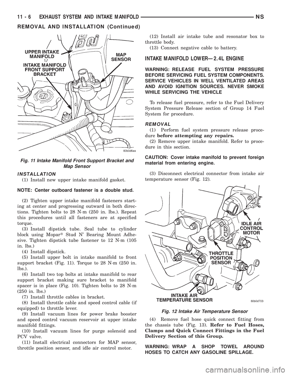
(5) Install upper bolt in intake manifold to front
support bracket (Fig. 11). Torque to 28 N´m (250 in.
lbs.).
(6) Install two top bolts at intake manifold to rear
support bracket making sure bracket to manifold
spacer is in place (Fig. 10). Tighten bolts to 28 N´m
(250 in. lbs.)
(7) Install throttle cables in bracket.
(8) Install throttle cable and speed control cable (if
equipped) to throttle lever.
(9) Install vacuum lines for power brake booster
and speed control vacuum reservoir at upper intake
manifold fittings.
(10) Install vacuum lines for purge solenoid and
PCV valve.
(11) Install electrical connectors for MAP sensor,
throttle position sensor, and idle air control motor.(12) Install air intake tube and resonator box to
throttle body.
(13) Connect negative cable to battery.
INTAKE MANIFOLD LOWERÐ2.4L ENGINE
WARNING: RELEASE FUEL SYSTEM PRESSURE
BEFORE SERVICING FUEL SYSTEM COMPONENTS.
SERVICE VEHICLES IN WELL VENTILATED AREAS
AND AVOID IGNITION SOURCES. NEVER SMOKE
WHILE SERVICING THE VEHICLE
To release fuel pressure, refer to the Fuel Delivery
System Pressure Release section of Group 14 Fuel
System for procedure.
REMOVAL
(1) Perform fuel system pressure release proce-
durebefore attempting any repairs.
(2) Remove upper intake manifold. Refer to proce-
dure in this section.
CAUTION: Cover intake manifold to prevent foreign
material from entering engine.
(3) Disconnect electrical connector from intake air
temperature sensor (Fig. 12).
(4) Remove fuel hose quick connect fitting from
the chassis tube (Fig. 13).Refer to Fuel Hoses,
Clamps and Quick Connect Fittings in the Fuel
Delivery Section of this Group.
WARNING: WRAP A SHOP TOWEL AROUND
HOSES TO CATCH ANY GASOLINE SPILLAGE.
Fig. 11 Intake Manifold Front Support Bracket and
Map Sensor
Fig. 12 Intake Air Temperature Sensor
11 - 6 EXHAUST SYSTEM AND INTAKE MANIFOLDNS
REMOVAL AND INSTALLATION (Continued)
Page 1269 of 1938
(5) Drain cooling system. Refer to Group 7, Cool-
ing System for procedure.
(6) Remove heater, and upper radiator hoses at
intake manifold.
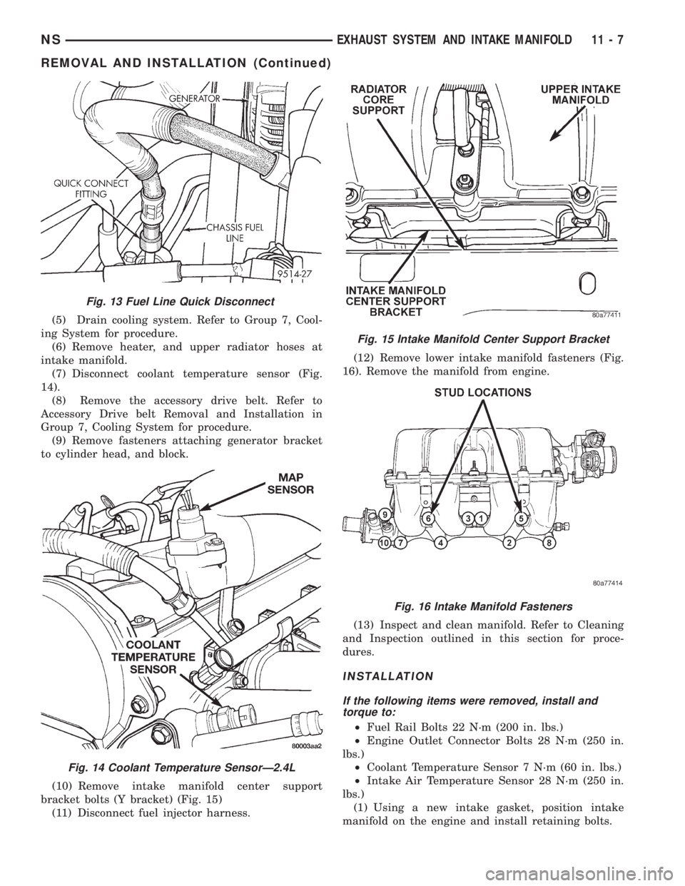
(7) Disconnect coolant temperature sensor (Fig.
14).
(8) Remove the accessory drive belt. Refer to
Accessory Drive belt Removal and Installation in
Group 7, Cooling System for procedure.
(9) Remove fasteners attaching generator bracket
to cylinder head, and block.
(10) Remove intake manifold center support
bracket bolts (Y bracket) (Fig. 15)
(11) Disconnect fuel injector harness.(12) Remove lower intake manifold fasteners (Fig.
16). Remove the manifold from engine.
(13) Inspect and clean manifold. Refer to Cleaning
and Inspection outlined in this section for proce-
dures.
INSTALLATION
If the following items were removed, install and
torque to:
²Fuel Rail Bolts 22 N´m (200 in. lbs.)
²Engine Outlet Connector Bolts 28 N´m (250 in.
lbs.)
²Coolant Temperature Sensor 7 N´m (60 in. lbs.)
²Intake Air Temperature Sensor 28 N´m (250 in.
lbs.)
(1) Using a new intake gasket, position intake
manifold on the engine and install retaining bolts.
Fig. 13 Fuel Line Quick Disconnect
Fig. 14 Coolant Temperature SensorÐ2.4L
Fig. 15 Intake Manifold Center Support Bracket
Fig. 16 Intake Manifold Fasteners
NSEXHAUST SYSTEM AND INTAKE MANIFOLD 11 - 7
REMOVAL AND INSTALLATION (Continued)