ignition DATSUN 210 1979 Repair Manual
[x] Cancel search | Manufacturer: DATSUN, Model Year: 1979, Model line: 210, Model: DATSUN 210 1979Pages: 548, PDF Size: 28.66 MB
Page 473 of 548
Body
Electdcal
System
INSPECTION
Check
the
following
items
if
blower
motor
fails
to
rotate
FUSE
To
check
for
burned
out
fuse
use
the
same
procedure
as
that
for
ordina
ry
fuses
with
a
circuit
tester
or
test
lamp
BLOWER
MOTOR
POWER
SUPPLY
Disconnect
blower
motor
harness
to
connect
main
harness
2
Connect
one
test
lamp
lead
wire
i
I
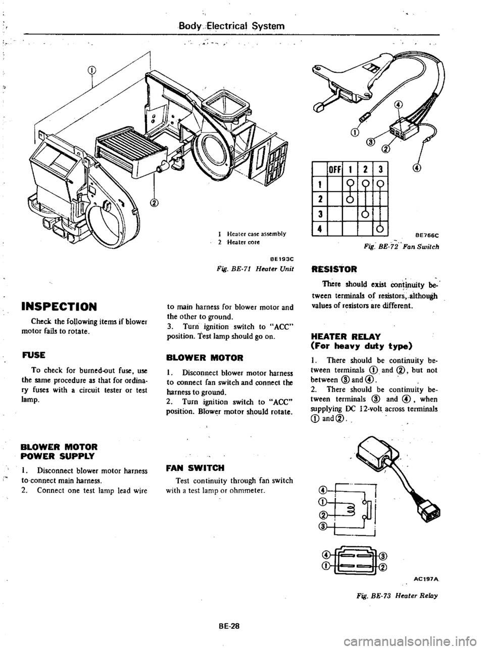
Heater
case
as
mbly
2
Heater
cote
BE193C
Fig
BE
71
Heater
Unit
to
main
harness
for
blower
motor
and
the
other
to
ground
3
Turn
ignition
switch
to
ACC
position
test
lamp
should
go
on
BLOWER
MOTOR
1
Disconnect
blower
motor
harness
to
connect
fan
switch
and
connect
the
harness
to
ground
2
Turn
ignition
switch
to
ACC
position
Blower
motor
should
rotate
FAN
SWITCH
Test
continuity
through
fan
switch
with
a
test
lamp
or
ohmmeter
BE
2B
OFF
1
2
3
I
1
0
01
2
I
3
0
I
4
01
BE766C
Fig
BE
72
Fan
Switch
RESISTOR
TItere
should
exist
continuity
be
tween
terminals
of
resistors
althouBh
values
of
resistors
are
different
HEATER
RELAY
For
heavy
duty
type
I
There
should
be
continuity
be
tween
terminals
D
and
@
but
not
between
@
and
@
2
There
should
be
continuity
be
tween
terminals
@
and
@
when
supplying
OC
12
volt
across
terminals
D
and@
I
@
I
I
j
i
i
@
fc
4@
j
I
V
AC197A
Fig
BE
73
Heater
Relay
Page 474 of 548
m
ii
I
ll
i
f
r
3
0
tl
i
a
iO
3
o
J
r
L
8
ffi
12V
BATTERY
I
STARTING
MOTOR
I
I
G
0
0
9
@@
@@
L
J
W
MAIN
RELAY
AIR
CONDITIONER
w
ALTERNATOR
SAND
B
TERMINALS
HEADLAMP
FUSE
BLOCK
I
WR
1
IGNITION
SWITCH
R
1
Note
@
i
W
Californta
models
Non
alifornt8
models
for
U
S
A
Non
CaliforOlB
FU
model
Canada
models
II
II
n
I
a
n
e
xI
ltZ
O
C
It
10
II
I
l
C
m
xl
0
l
OJ
3
0
n
CJ
II
m
al
CD
Z
0
2
a
t
CIl
xI
I
0
c
l
OJ
3
m
2
l
C
Z
o
CJ
m
CJ
Page 483 of 548

m
i
J
Ol
dQ
I
ll
to
tl
i
Cl
a
aJ
toom
a
0
is
r
0
BATTERY
A
G
ffiJ
rr
l
M
WR
FUSIBLE
LINK
ENGINE
HARNESS
No
2
n
o
Ot
G
l
KG
u
o
Ot
RB
RB
9ACK
UP
LAMP
SWITCH
15
SPEEO
MIT
MOOELI
Bl
RB
LT
G
INHIBITOR
SWITCH
IAfT
MOOELl
GO
ION
S1
OnQQ
o
16
I
10
s
II
0
1
IGNITION
SWITCH
Q
BW
I
t
WA
FUSE
BLOCK
o
o
1
G
I
BL
BOOY
o
HARNESS
J
00
I
RB
oo
RB
RB
Q
l
0
9
1
I
R
I
rfRB
ac
00
0
o
9
B
INSTRUMENT
HARNESS
R
l
WAGON
o
n
oo
B
o
I
1
L
WARNING
BUZZER
r
REAR
COM91NATION
LAMP
IL
H
1
tJ
l
mO
gm
m
xl
REAR
COMBINATION
LAMP
IR
H
I
R
BACK
UP
LAMP
t1
CJ
l
xl
n
0
l
0
Z
15
z
BACK
UP
LAMP
I
C
lI
i
lI
OJ
0
Cl
m
CD
0
CIl
UI
CO
3
Page 487 of 548

Fuel
level
gauge
Condition
Fuel
level
gauge
does
not
operate
Pointer
indicates
only
F
10
position
Fuel
level
gauge
does
not
operate
accurately
Body
Electrical
System
Probable
cause
Faulty
fuel
gauge
tank
unit
or
loose
unit
terminal
connection
pointer
deflects
when
fuel
gauge
tank
unit
yellow
wire
isgrounded
Faulty
fuel
level
gauge
Loose
connection
or
open
circuit
Faulty
fuel
gauge
tank
unit
Pointer
drops
below
E
0
mark
when
ignition
switch
is
turned
off
Faulty
fuellevel
gauge
pointer
still
indicates
F
10
position
when
ignition
switch
is
turned
off
Faulty
fuel
gauge
tank
unit
Faulty
fuel
level
gauge
Poor
or
loose
connection
Faulty
gauge
voltage
regulator
Gauge
pointer
fluctuates
excessively
Condition
Water
temperature
gauge
Probable
cause
Water
temperature
gauge
does
not
operate
Gauge
indicates
only
maximum
temperature
Water
temperature
gauge
does
not
operate
accurately
Faulty
therrruiJ
transmitter
or
loose
terminal
connection
When
yellow
white
wire
to
thermal
trans
mitter
is
grounded
gauge
pointer
fluctuates
Faulty
water
temperature
gauge
Open
circuit
Faulty
thermal
transmitter
Gauge
pointer
returns
to
original
position
when
ignition
switch
is
turned
off
Faulty
water
temperature
gauge
Gauge
pointer
indicates
maximum
tempera
ture
even
after
ignition
switch
is
turned
off
Faulty
water
temperature
gauge
Loose
or
poor
connection
BE
42
Corrective
action
Replace
fuel
gauge
tank
unit
or
correct
terminal
connection
Replace
Check
wiring
and
or
repair
connection
Replace
Replace
Replace
Replace
fuel
level
gauge
Correct
connector
terminal
contact
Replace
fuel
level
gauge
Main
or
water
temperature
gauge
Sub
Corrective
action
Replace
thermal
transmitter
or
correct
ter
minal
connection
Replace
water
temperature
gauge
Replace
thermal
transmitter
Replace
water
temperature
gauge
Replace
water
temperature
gauge
Correct
connector
terminal
contact
Page 489 of 548
cIo
CD
m
t
tl
3
Cl
4
Ii
ii
C
l
I
i
I
ll
g
toom
a
ll
CALIFORNIA
ANO
BATTERY
FU
MOOELS
R
G
ff
w
G
M
wr
N
Q
WR
ALTERNATOR
ANO
IC
NON
cALIFOR
IA
VOLTAGE
REGULATOR
ANO
CANAOA
MO
S
I
fh
WR
B
i
W
i
C
@
J
W
l
9
i
j
@
Q
B
LB
OIL
PRESSURE
SWITCH
0
I
I
l
lOCI
OfflACC
OH
SI
Ys
j
D
01
mQ
IS
i
I
l
I
s
II
10
J
J
SWITCH
IGNITION
iji
BY
wr
1
I
1
IW
BRAKE
FLUIO
LEVEL
SWITCH
Ot
o
BJ
JO
0
Y
l
I
AUTO
cHOKE
RELAY
V
I
r
I
MAIN
HARNESS
FUSE
BLOCK
0
0
lOA
cr
L
lOA
cr
G
1
r
L
BL
HANO
BRAKE
SWITCH
G
J
i
INSTRUMENT
HARN
ESS
fG
YG
10
OMB
N
AT
qN
ETER
o
BRAKE
0
WARNING
LAMP
100
G
O
00
3
YB
f
G
WR
J
I
0
1
Fo
o
e
i
1
z
YB
OIL
PRESSURE
WARNING
LAMP
J
lI
a
Ill
z
11
1
III
Z
G
Ill
11
1
Ut
0
iUt
Ill
alii
11
1
I
a
i
l
i
Ill
Z
i
a
X
OJ
o
Cl
m
CD
o
CIl
l
3
Page 490 of 548

m
l
U1
ii
I
ll
cio
i
t
s
a
Cl
t
m
l
e
BATTERY
8
GtG
ug
ew
FUSIBLE
LINK
BELT
TIMER
I
i
DD
l
J
G
if
I
lOCI
OffIACCI
aNI
Sf
I
0
0
8
i
i
16
I
S
IGNITION
SWITCH
FUSE
BLOCK
B
0
lOA
G
L
BL
ORIVER
S
BELT
SWITCH
tl
WARNING
LAMP
iP
aB
ij
II
VB
L
I
81
WB
I
t
OI
00
00
0
0
B
B
B
B
feB
WARNING
BUZZER
III
e
IIll
a
I
III
Z
i
C
OJ
o
Cl
m
CD
n
o
Q
CIl
en
l
3
Page 491 of 548
Body
Electrical
Sy
tem
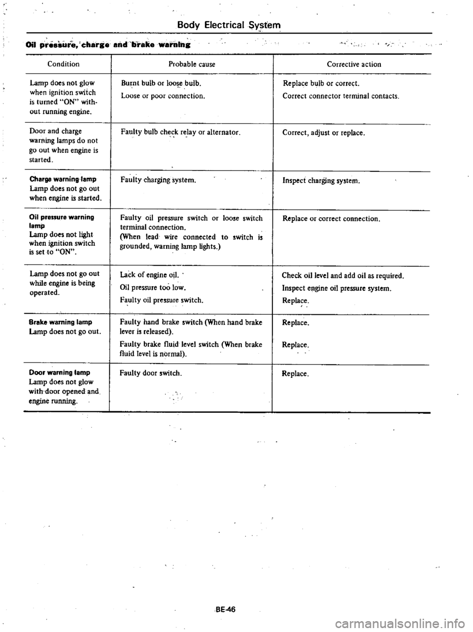
Oil
pr
re
charg
and
brake
warillng
Condition
Lamp
does
not
glow
when
ignition
switch
is
turned
ON
with
out
running
engine
Door
and
charge
warning
lamps
do
not
go
out
when
engine
is
started
Charge
waming
amp
Lamp
does
not
go
out
when
engine
is
started
Oil
pressure
warning
lamp
Lamp
does
not
light
when
ignition
switch
is
set
to
ON
Lamp
does
not
go
out
while
engine
is
being
operated
Brake
warning
lamp
Lamp
does
not
go
out
Door
warning
lamp
Lamp
does
not
glow
with
door
opened
and
engine
running
Probable
cause
Burnt
bulb
or
loo
ebulb
Loose
or
poor
connection
Faully
bulb
check
relay
or
alternator
Faully
charging
system
Faully
oil
pressure
switch
or
loose
switch
terminal
connection
When
lead
wire
connected
to
switch
is
grounded
warning
lamp
lights
Lack
of
engine
oil
Oil
pressure
too
low
Faully
oil
pressure
switch
Faulty
hand
brake
switch
When
hand
brake
lever
is
released
Faully
brake
fluid
level
switch
When
brake
fluid
level
is
normal
Faully
door
switch
BE
46
Corrective
action
Replace
bulb
or
correct
Correct
connector
terminal
contacts
Correct
adjust
or
replace
Inspect
charging
system
Replace
or
correct
connection
Check
oil
level
and
add
oil
as
required
Inspect
engine
oil
pressure
system
Replace
Replace
Replace
Replace
Page 492 of 548
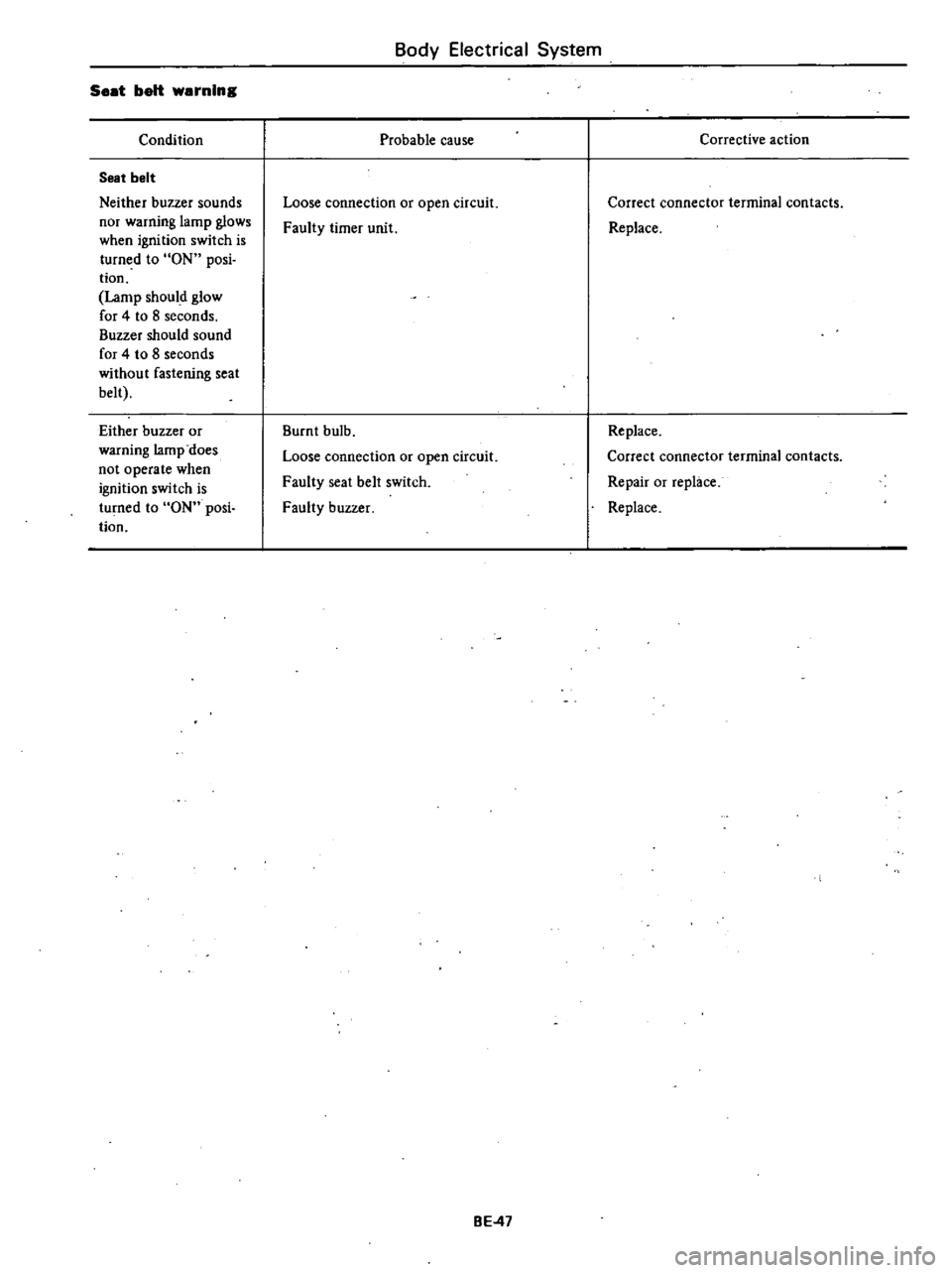
Seat
belt
warning
Condition
Seat
belt
Neither
buzzer
sounds
nor
warning
lamp
glows
when
ignition
switch
is
turned
to
ON
posi
tion
Lamp
should
glow
for
4
to
8
seconds
Buzzer
should
sound
for
4
to
8
seconds
without
fastening
seat
belt
Either
buzzer
or
warning
lamp
does
not
operate
when
ignition
switch
is
turned
to
ON
posi
tion
Body
Electrical
System
Probable
cause
Loose
connection
or
open
circuit
Faulty
timer
unit
Burnt
bulb
Loose
connection
or
open
circuit
Faulty
seat
belt
switch
Faulty
buzzer
BE
47
Corrective
action
Correct
connector
terminal
contacts
Replace
Replace
Correct
connector
terminal
contacts
Repair
or
replace
Replace
Page 493 of 548

m
J
Co
5
oil
tl
Cl
s
5
Q
0
0
WAS
ER
MOTOR
t
l
I
o
BATTERY
A
G
ll
J
wr
FUSIB
E
LINK
Off
UN
HI
WASH
11
J
BY
9
n
13
4d
1
o
14
J
I
Q
I
16
m
LW
2
0
u
J
WIPER
ANO
WASHER
SWITCH
I
lGCK
OfF
ACe
OM
Sf
2
0
OnOOB
m
iL
IG
i
I
0
S
00
A
II
WR
LB
IGNITION
SWITCH
Off
ON
WASHV
iW
REAR
WIPER
0
0
11
l
R
SWITCH
I
0
Q
I
2
I
B
HATCHBACK
0
I
I
3
o
II
LR
n
I
I
III
I
I
1
I
1
iI
Y
WIPER
MOTOR
LR
ti
BY
B
R
r
REAR
WASHER
MOTOR
IHATCHBACK
ANO
i
WAGON
Em
I
m
IIIn
zoot
a
11
1
I
a
E
lI
11
1
a
n
Jon
ZII
aen
i
III
a
io
OJ
a
It
8
0
It
m
l
l
In
l
CIl
l
3
HATCHBACK
LR
BOOYHARNESS
z
I
L
I
OO
B
iOl
c
TO
REAR
OEFOGGER
I
LR
rLB
1
I
3
0
i
BW
R
LRh
ftn
WAGON
0
0
r
o
REAR
WIPER
MOTOR
CRWl
T1
c
l
Rlif
1
I
mC
BilW
lJ
I
g
LR
Jj
i
1
FUSE
BLOCK
Page 495 of 548

m
ii
lil
cIo
00
tl
i
3
Cl
0
m
0
g
fB
Jo
0
0
Ef1
CALIFORNIA
ANO
FU
MOOELS
t
f
G
W
g
dG
I
WR
FUSIBLE
LINK
8
G
uQ
t
WR
NON
cALIFORNIA
AND
CANAOA
MOOELS
J
TORQUE
CONVERTER
C
ao
GY
INOICATOR
LAMP
5
l
1
00
GW
I
BATTERY
CCOHST7
i
lOCK
Off
A
B
OO
C
I
ti
II
v
u
1
WITCH
IGNITION
S
2ND
Oil
lS1
B
C
C
AI8
C
I
5
A
8
I
QIQ
Q
Q
J1
0
0
I
0
6
B
6
0
7
Q
QIQIQ
8
0
0
0
9
O
I
LIGHTING
SWITCH
Z
1
D
Z
m
en
WR
LB
1lRG
GW
INSTRUMENT
HARNESS
j
lO
GW
I
oGW
GY
00
GY
LW
LW
I@o
00
og
B
0
u
B
LW
LB
I
I
0
0
J8
RG
w
1
0
r
O
FUSE
BLOCK
LW
ClO
LW
W
t
WB
1
r
GY
GW
RAOIO
ffi
i
n
In
U
L
J
UJ
J
U
WB
O
W
SPEAKER
OJ
o
Cl
m
CD
C
e
CIl
en
3