ECU DATSUN 210 1979 User Guide
[x] Cancel search | Manufacturer: DATSUN, Model Year: 1979, Model line: 210, Model: DATSUN 210 1979Pages: 548, PDF Size: 28.66 MB
Page 81 of 548
2
Loosen
belt
then
remove
fan
blade
from
torque
coupling
and
torque
coupling
and
pulley
from
hub
Air
conditioning
system
equipped
models
only
4
Remove
pump
assembly
and
gas
ket
from
front
cover
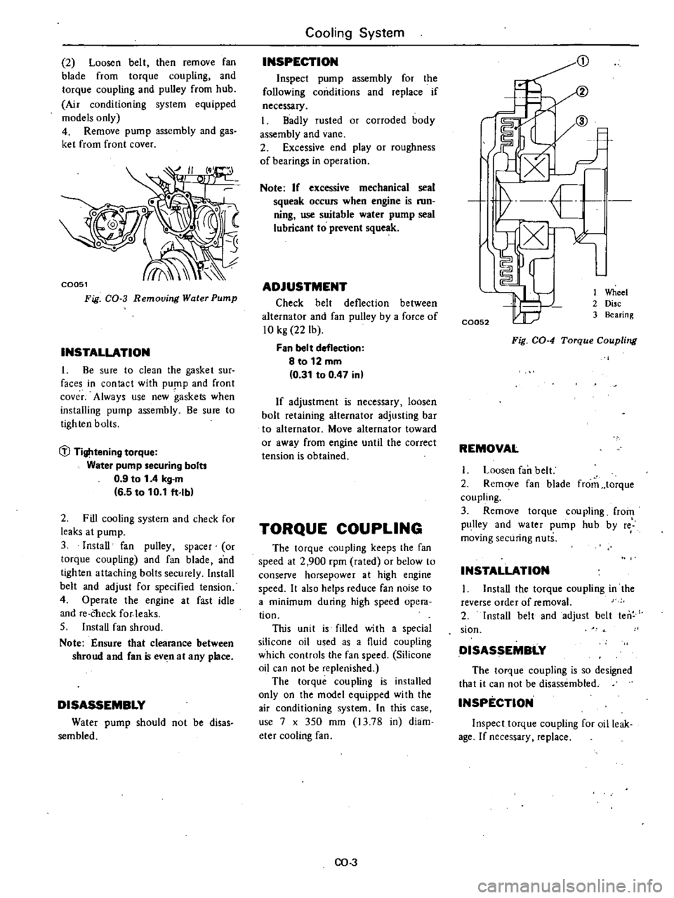
C0051
Fig
CO
3
Removing
Water
Pump
INSTALLATION
1
Be
sure
to
clean
the
gasket
sur
faces
in
contact
with
pU
flP
and
front
cover
Always
use
new
gaskets
when
installing
pump
assembly
Be
sure
to
tighten
bolts
i
l
Tightening
torque
Water
pump
securing
bolts
0
9
to
1
4
kg
m
6
5
to
10
1
ft
Ib
2
Fill
cooling
system
and
check
for
leaks
at
pump
3
InstaD
fan
pulley
spacer
or
torque
coupling
and
fan
blade
and
tighten
attaching
bolts
securely
Install
belt
and
adjust
for
specified
tension
4
Operate
the
engine
at
fast
idle
and
re
Check
for
leaks
S
Install
fan
shroud
Note
Ensure
that
clearance
between
shroud
and
fan
even
at
any
place
DISASSEMBLY
Water
pump
should
not
be
disas
sembled
Cooling
System
INSPECTION
Inspect
pump
assembly
for
the
following
conditions
and
replace
if
necessary
I
Badly
rusted
or
corroded
body
assembly
and
vane
2
Excessive
end
play
or
roughness
of
bearings
in
operation
Note
If
excessive
mechanical
seal
squeak
occurs
when
engine
is
mn
ning
use
suitable
water
pump
seal
lubricant
to
prevent
squeak
ADJUSTMENT
Check
belt
deflection
between
alternator
and
fan
pulley
by
a
force
of
10
kg
22
Ib
Fan
belt
deflection
8
to
12
mm
0
31
to
0
47
in
If
adjustment
is
necessary
loosen
bolt
retaining
alternator
adjusting
bar
to
alternator
Move
alternator
toward
or
away
from
engine
until
the
correct
tension
is
obtained
TORQUE
COUPLING
The
torque
coupling
keeps
the
fan
speed
at
2
900
rpm
rated
or
below
to
conserve
horsepower
at
high
engine
speed
It
also
helps
reduce
fan
noise
to
a
minimum
during
high
speed
opera
tion
This
unit
is
filled
with
a
special
silicone
oil
used
as
a
fluid
coupling
which
controls
the
fan
speed
Silicone
oil
can
not
be
replenished
The
torque
coupling
is
installed
only
on
the
model
equipped
with
the
air
conditioning
system
In
this
case
use
7
x
350
mm
13
78
in
diam
eter
cooling
fan
CO
3
C0052
t
Wheel
2
Disc
3
Bearing
Fig
CO
4
Torque
Coupling
REMOVAL
Lousen
fan
belt
2
Remove
fan
blade
from
torque
coupling
3
Remove
torque
coupling
from
pulley
and
water
pump
hub
by
re
moving
securing
nuts
INSTALLATION
I
InstaD
the
torque
coupling
in
the
reverse
order
of
removal
2
Install
belt
and
adjust
belt
ten
sian
DISASSEMBLY
The
torque
coupling
is
so
designed
that
it
can
not
be
disassembled
INSPECTION
Inspect
torque
coupling
for
oil
leak
age
If
necessary
replace
Page 88 of 548
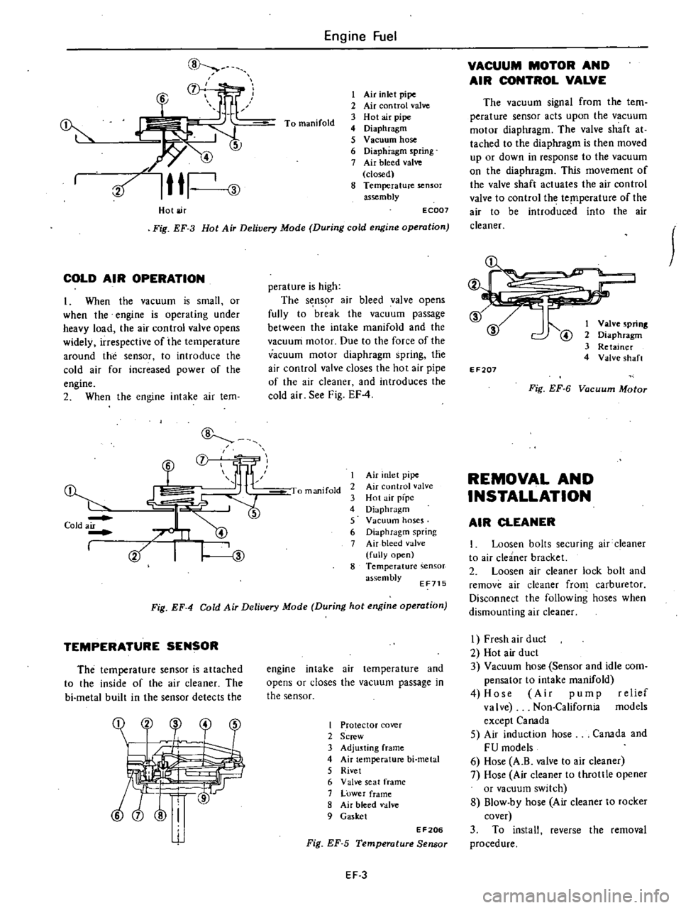
Hot
air
Engine
Fuel
To
manifold
I
Air
inlet
pipe
2
Air
con
trol
valve
3
Hot
air
pipe
4
Diaphragm
5
V
Bellum
hose
6
Diaphragm
spring
7
Air
bleed
valve
closed
8
Temperature
sensor
assembly
Fig
EF
3
Hot
Air
Delivery
Mode
During
cold
engine
operation
EC007
COLD
AIR
OPERATION
1
When
the
vacuum
is
small
or
when
the
engine
is
operating
under
heavy
load
the
air
control
valve
opens
widely
irrespective
of
the
temperature
around
the
sensor
to
introduce
the
cold
air
for
increased
power
of
the
engine
2
When
the
engine
intake
air
tem
Cold
air
I
L
CD
mf
LlF
JII
1
perature
is
high
The
s
ns
r
air
bleed
valve
opens
fully
to
break
the
vacuum
passage
between
the
intake
manifold
and
the
vacuum
motor
Due
to
the
force
of
the
vacuum
motor
diaphragm
spring
tne
air
control
valve
closes
the
hot
air
pipe
of
the
air
cleaner
and
introduces
the
cold
air
See
Fig
EF
4
I
manifold
I
Air
nlet
pipe
2
Air
control
valve
3
Hot
air
pfpc
4
Diaphragm
5
Vacuum
hoses
6
Diaphragm
spring
7
Air
bleed
alve
fully
open
8
Temperature
assembly
EF715
Fig
EF
4
Cold
Air
Deliuery
Mode
During
hot
engine
operation
TEMPERATURE
SENSOR
The
temperature
sensor
is
attached
to
the
inside
of
the
air
cleaner
The
bi
metal
built
in
the
sensor
detects
the
engine
intake
air
temperature
and
opens
or
closes
the
vacuum
passage
in
the
sensor
I
Protector
cover
2
Screw
3
Adjusting
frame
4
Air
temperature
bi
metal
5
Rivet
6
Valve
seat
frame
7
Lower
frame
8
Air
bleed
valve
9
Gasket
EF206
Fig
EF
5
Temperature
Sensor
EF
3
VACUUM
MOTOR
AND
AIR
CONTROL
VALVE
The
vacuum
signal
from
the
tem
perature
sensor
acts
upon
the
vacuum
motor
diaphragm
The
valve
shaft
at
tached
to
the
diaphragm
is
then
moved
up
or
down
in
response
to
the
vacuum
on
the
diaphragm
This
movement
of
the
valve
shaft
actuates
the
air
control
valve
to
control
the
temperature
of
the
air
to
be
introduced
into
the
air
cleaner
@
@
@
I
Valve
spring
2
Diaphragm
3
Retainer
4
Valve
shaft
EF207
Fig
EF
6
Vacuum
Motor
REMOVAL
AND
INSTALLATION
AIR
CLEANER
I
Loosen
bolts
securing
air
cleaner
to
air
cleaner
bracket
2
Loosen
air
cleaner
lock
bolt
and
remove
air
cleaner
from
carburetor
Disconnect
the
following
hoses
when
dismounting
air
cleaner
I
Fresh
air
duct
2
Hot
air
duct
3
Vacuum
hose
Sensor
and
idle
com
pensator
to
intake
manifold
4
Hose
Air
pump
relief
valve
Non
California
models
except
Canada
5
Air
induction
hose
Canada
and
FU
models
6
Hose
A
B
valve
to
air
cleaner
7
Hose
Air
cleaner
to
throttle
opener
or
vacuum
switch
8
Blow
by
hose
Air
cleaner
to
rocker
cover
3
To
install
reverse
the
removal
procedure
Page 89 of 548
TEMPERATURE
SENSOR
Removal
I
Using
pliers
flatten
clip
con
necting
vacuum
hose
to
sensor
vacuum
tube
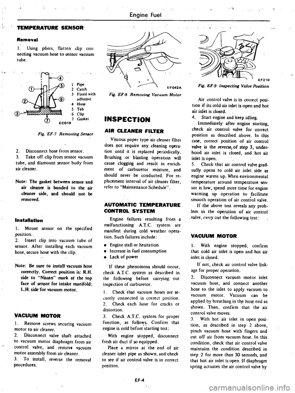
1
Pipe
2
Catch
3
Fixed
with
adhesive
4
Hose
5
Tab
6
Clip
7
Gasket
EC019
Fig
EF
7
Removing
Seruor
2
Disconnect
hose
from
sensor
3
Take
off
clip
from
sensor
vacuum
tube
and
dismount
sensor
body
from
air
cleaner
Note
The
gasket
between
sensor
and
air
cleaner
is
bonded
to
the
air
cleaner
side
and
should
not
be
removed
Installation
Mount
sensor
on
the
specified
position
2
Insert
clip
into
vacuum
tube
of
sensor
After
installing
each
vacuum
hose
secure
hose
with
the
clip
Note
Be
sure
to
install
vacUl
11n
hose
correctly
Correct
position
is
R
H
side
to
Ntisan
mark
at
the
top
face
of
sensor
for
intake
manifold
L
H
side
for
Deuum
motor
VACUUM
MOTOR
1
Remove
screws
securing
vacuum
motor
to
air
cleaner
2
Disconnect
valve
shaft
attached
to
vacuum
motor
diaphragm
from
air
control
valve
and
remove
vacuum
motor
assembly
from
air
cleaner
3
To
install
reverse
the
removal
procedures
Engine
Fuel
Fig
EF
8
Removing
Vacuum
Motor
INSPECTION
AIR
CLEANER
FILTER
Viscous
paper
type
air
cleaner
filter
does
o
ot
rt
quire
any
cleaning
opera
tion
until
it
is
replaced
periodically
Brushing
or
blasting
operation
will
cause
clogging
and
result
in
enrich
ment
of
carburetor
mixture
and
should
never
be
conducted
For
reo
placement
interval
of
air
cleaner
filter
refer
to
Maintenance
Schedule
AUTOMATIC
TEMPERATURE
CONTROL
SYSTEM
Engine
failures
resulting
from
a
malfunctioning
A
T
C
system
are
manifest
during
cold
weather
opera
tion
Such
failures
include
Engine
stall
or
hesitation
Increase
in
fuel
consumption
Lack
of
power
If
these
phenomena
should
occur
check
A
T
e
system
as
described
in
the
following
before
carrying
out
inspection
of
carburetor
I
Check
that
vacuum
hoses
are
se
l
urely
connected
in
correct
position
2
Check
each
hose
for
cracks
or
distortion
3
Check
A
T
C
system
for
proper
function
as
follo
ys
Confirm
that
engine
is
cold
before
starting
test
With
engine
topped
disconnect
fresh
air
duct
if
so
equipped
Place
a
mirror
at
the
end
of
air
cleaner
inlet
pipe
as
shown
and
check
to
see
if
air
control
valve
is
in
correct
position
EF
4
Fig
EF
9
Inspecting
Valve
Po
man
Air
control
valve
is
in
correct
posi
tion
if
its
cold
air
inlet
is
open
and
hot
air
inlet
is
closed
4
Start
engine
and
keep
idling
Immediately
after
engine
starting
check
air
control
valve
for
correct
position
as
described
above
In
this
case
correct
position
of
air
control
valve
is
the
reverse
of
step
3
under
hood
air
inlet
is
closed
and
hot
air
inlet
is
open
S
Check
that
air
control
valve
grad
ually
opens
to
cold
air
inlet
side
as
engine
warms
up
When
environmental
temperature
around
temperature
sen
sor
is
low
spend
more
time
for
engine
warming
up
operation
to
facilitate
smooth
operation
of
air
control
valve
If
the
above
test
reveals
any
prob
lem
in
the
opera
ion
of
air
control
valve
carry
out
the
following
test
VACUUM
MOTOR
I
With
engine
stopped
confirm
that
cold
air
inlet
is
open
and
hot
air
inlet
is
c1
Sed
If
not
check
air
control
valve
link
age
for
proper
operation
2
DiscoJln
ct
ac
um
motor
inlet
vacuum
hose
and
connect
another
hose
to
the
inlet
to
apply
vacuum
to
vacuum
motor
Vacuum
can
be
appli
d
by
breathing
in
tile
hos
e
end
as
shown
Then
confirm
that
the
air
control
valve
moves
3
With
hot
air
inlet
in
open
posi
tion
as
described
in
step
2
above
pinch
vacuum
hose
with
fingers
and
cut
off
air
from
vacuum
hose
In
this
condition
check
that
air
control
valve
maintains
the
condition
described
in
step
2
for
more
than
30
seconds
and
that
hot
air
inlet
is
open
If
diaphragm
spring
actuates
the
air
control
valve
by
Page 91 of 548
Engine
Fuel
S
Idle
compensator
is
ill
good
order
if
a
hissing
sound
is
heard
when
its
temperature
reaches
operating
tern
perature
If
not
replace
idle
compensator
ldlerompensator
l
b
l
r
I
No
1
60
to
700C
140
to
15
Of
No
2
70
to
800C
158
to
1760F
FUEL
FILTER
DESCRIPTION
t
t
I
J
i
l
The
fuel
filter
is
a
cartridge
type
It
useS
a
paper
element
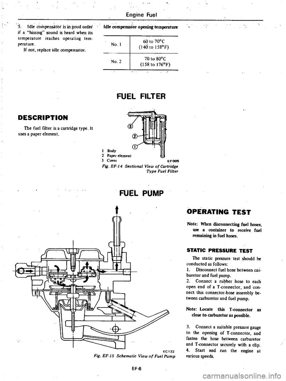
1
Body
2
Paper
element
3
Cover
EFOOS
Fig
EF
14
Sectional
View
of
Cartridge
Type
FuelFilte
FUEL
PUMP
t
j
f
EC132
Fig
EF
15
Schematic
View
of
Fuel
Pump
EF
6
OPERATING
TEST
Note
When
disconnecting
fuel
hoses
me
a
container
to
receive
fuel
remaining
in
fuel
hoses
STATIC
PRESSURE
TEST
The
static
pressure
test
should
be
conducted
as
follows
I
Disconnect
fuel
hose
between
car
buretor
and
fuel
pump
2
Connect
a
rubber
hose
to
each
open
end
of
aT
connector
and
con
nect
this
connector
hose
assembly
be
tween
carburetor
and
fuel
pump
Note
Locate
this
T
eonnector
as
close
to
carburetor
as
possible
3
Connect
a
suitable
pressure
gauge
to
the
opening
of
T
connector
and
fasten
the
hose
between
carburetor
and
T
connector
secUrely
with
a
clip
4
Start
and
run
the
engine
at
various
speeds
Page 92 of 548
5
The
pressure
gauge
indicates
static
fuel
pressure
in
the
line
The
gauge
reading
should
be
within
the
specified
value
Fuel
pump
pressure
0
21
to
0
27
kg
em2
3
0
to
3
8
pli
I
Note
If
the
fuel
in
the
carburetor
float
chamber
has
run
out
and
engine
has
stopped
remove
clip
and
pour
fuel
into
carburetor
Fasten
clip
securely
and
repeat
static
pres
sure
test
If
pressure
is
not
within
the
specifi
ed
limit
remove
pump
as
an
assembly
CAPACITY
TEST
The
capacity
test
is
conducted
only
when
static
pressure
is
within
the
specification
To
conduct
this
test
proceed
as
follows
1
Disconnect
pressure
gauge
from
T
connector
and
in
its
vacant
place
install
a
suitable
container
as
a
fuel
sump
2
Start
engine
and
run
at
1
000
pm
3
Pump
should
deliver
the
specified
amouni
of
fuel
If
little
or
no
fuel
flows
from
open
end
of
pipe
it
is
an
indication
that
fuel
line
is
clogged
or
pump
is
mal
functioning
Fuel
pump
capacity
450
cc
27
46
eu
inl
min
at
1
000
rpm
REMOVAL
AND
INSTALLATION
Note
When
disconnecting
fuel
lines
use
a
container
to
receive
fuel
remaining
in
fuel
hoses
I
Disconnect
inlet
and
outlet
fuel
hoses
from
fuel
pump
2
Remove
fuel
pump
3
To
install
reverse
the
order
of
removal
Engine
Fuel
DISASSEMBLY
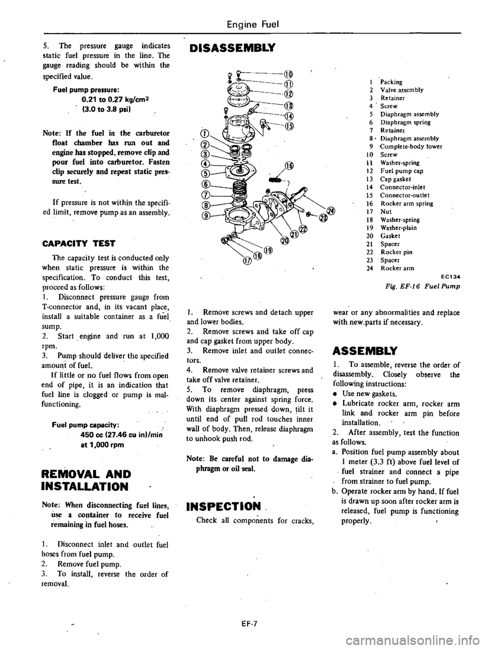
@@
@@
@
@@
1
Remove
screws
and
detach
upper
and
lower
bodies
2
Remove
screws
and
take
off
cap
and
cap
gasket
from
upper
body
3
Remove
inlet
and
outlet
connee
tors
4
Remove
valve
retainer
screws
and
take
off
valve
retainer
S
To
remove
diaphragm
press
down
its
center
against
spring
force
With
diaphragm
pressed
down
ilt
it
until
end
of
pull
rod
touches
inner
wall
of
body
Then
release
diaphragm
to
unhook
push
rod
Note
Be
careful
not
to
damage
dia
phragm
or
oil
seal
INSPECTION
Check
all
components
for
cracks
EF
7
I
Packing
2
Valve
a5scm
bly
3
Retainer
4
Screw
5
Diaphragm
assembly
6
Diaphragm
spring
7
Retainer
8
Diaphragm
assembly
9
Complete
body
lower
10
Screw
11
Washer
spring
12
Fuel
pump
cap
13
Cap
gasket
14
Connector
inlet
15
Connector
outlet
16
Rocker
arm
spring
17
Nut
18
Washer
spring
19
Washer
pJain
20
Gasket
21
Spacer
22
Rocker
pin
23
Spacer
24
Rocker
arm
EC134
Fig
EF
16
Fuel
Pump
wear
or
any
abnormalities
and
replace
with
new
parts
if
necessary
ASSEMBLY
I
To
assemble
reverse
the
order
of
disassembly
Closely
observe
the
following
instructions
Use
new
gaskets
Lubricate
rocker
arm
rocker
arm
link
and
rocker
arm
pin
before
installation
2
After
assembly
test
the
function
as
follows
a
Position
fuel
pump
assembly
about
I
meter
3
3
ft
above
fuel
level
of
fuel
strainer
and
connect
a
pipe
from
strainer
to
fuel
pump
b
Operate
rocker
arm
by
hand
If
fuel
is
drawn
up
soon
after
rocker
arm
is
released
fuel
pump
is
functioning
properly
Page 102 of 548
AUTOMATIC
CHOKE
MECHANISM
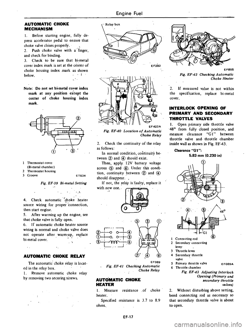
I
Before
starting
engine
fully
de
press
accelerator
pedal
to
ensure
that
choke
valve
closes
properly
2
Push
choke
valve
wi
th
a
finger
and
check
for
binding
3
Check
to
be
sure
that
bi
metal
cover
index
mark
is
set
at
the
center
of
choke
housing
index
mark
as
shown
below
I
Note
Do
not
set
b
metal
cover
index
mark
at
any
position
except
the
center
of
choke
housing
index
mark
CD
@
Thermosta
t
covel
Bi
metal
chamber
2
Thermostat
housing
3
Groove
E
T034
Fig
EF
39
Bi
metal
Setting
4
Check
automatic
choke
heater
source
wiring
for
proper
connection
then
start
engine
S
After
warming
up
the
engine
see
that
choke
valve
is
fully
open
6
If
automatic
choke
heater
source
wiring
is
normal
and
choke
valve
does
not
operate
after
warm
up
replace
bi
metal
cover
AUTOMATIC
CHOKE
RELAY
The
automatic
choke
relay
is
local
ed
in
the
relay
box
I
Remove
automatic
choke
relay
by
removing
two
securing
screws
Engine
Fuel
II
EF422A
Fig
EF
40
Location
of
Automatic
Choke
Relay
2
Check
the
continuity
of
the
relay
as
follows
In
normal
condition
continuity
be
tween
CV
and
@
should
exist
Then
apply
l2V
battery
voltage
across
CID
and
@
Under
this
condi
tion
contin
ity
between
CV
and
@
should
disappear
If
not
the
relay
is
faulty
replace
it
W
hWO
CID
CD
CV
o
0
@
Q
I
o
r
@
CID
@
EF989
Fig
EF
41
Checking
Automatic
Choke
Relay
AUTOMATIC
CHOKE
HEATER
I
Measure
resistance
of
choke
heater
Specified
resistance
is
3
7
to
8
9
ohms
EF
17
EF855
Fig
EF
42
Checking
Automatic
Choke
Heater
2
If
measured
value
is
not
within
the
specification
replace
bi
metal
cover
INTERLOCK
OPENING
OF
PRIMARY
AND
SECONDARY
THROTTLE
VALVES
1
Open
primary
side
throttle
valve
480
from
fully
closed
position
and
measure
clearance
G
1
between
throttle
valve
and
throttle
chamber
inside
wall
as
shown
in
Fig
EF
43
Clearance
6G1
5
83
mm
0
230
in
@
J
3
480
r
mit
GI
6
1
Connecting
rod
2
Secondary
connecting
lever
3
Throttle
lever
4
Secondary
throttle
valve
5
Primary
throttle
valve
6
Throttle
chamber
Fig
EF
43
Adjusting
Interlock
Opening
Primary
and
lecondary
throttle
values
2
Without
disturbing
above
setting
bend
connecting
rod
as
necessary
so
that
secondary
throttle
valve
is
about
to
open
E
F089A
Page 131 of 548

following
functions
without
affecting
the
effectiveness
of
the
exhaust
emis
sion
control
system
Minimizes
exhaust
gas
tempera
ture
rise
2
Minimizes
horsepower
losses
reo
sulting
from
air
injection
into
the
exhaust
system
3
Protects
pump
from
excessive
back
pressure
To
carburetor
air
cleaner
Secondary
ir
Not
actuated
To
carburetor
air
cleaner
J
l
Secondary
sir
Actuated
EC294
Fig
EC
18
Air
Pump
Relief
Valve
c
A
C
valve
Californiamodels
The
C
A
C
valve
controls
the
quantity
of
secondary
air
fed
from
the
air
pump
according
to
the
load
condi
tion
and
it
discharges
the
secondary
air
into
the
atmosphere
to
prevent
overheating
of
the
catalytic
converter
This
valve
is
operated
by
intake
manifold
vacuum
and
air
pump
dis
charge
pressure
When
intake
manifold
vacuum
is
small
or
in
the
high
load
range
the
No
2
valve
opens
when
it
is
great
or
in
the
low
load
range
the
No
I
valve
opens
If
air
pump
discharge
pressure
is
large
or
the
engine
is
running
at
a
high
speed
the
No
3
valve
opens
admitting
the
air
pump
discharge
pressure
to
the
No
2
dia
phragm
chamber
of
the
C
A
C
valve
mission
Control
System
and
opening
ihe
No
i
valve
At
this
point
the
No
2
valve
serves
as
a
relief
valve
F
111
air
pump
No
3
valve
EC787
Fig
EC
19
C
A
C
Valve
I
Engine
in
low
speed
and
light
load
When
the
engine
is
operating
under
these
conditions
intake
vacuum
is
high
The
No
2
valve
unitized
with
the
No
I
diaphragm
is
lifted
by
the
intake
manifold
vacuum
pushing
up
the
No
I
valve
These
valves
will
then
stop
at
a
position
where
a
balanced
condition
exists
between
air
pump
discharge
pressure
an
d
spring
tension
acting
on
the
No
I
and
No
2
valves
The
No
2
jiaphragm
however
does
not
move
due
to
low
engine
speed
low
air
pump
discharge
pressure
and
spring
tension
acting
on
the
No
3
valve
For
this
reason
these
valves
are
brought
to
a
balanced
condition
To
intake
manifold
t
i
l
3
Spring
4
ValveNo
3
5
Di
phragm
No
I
I
@
6
Spring
7
Valve
No
1
8
Valve
No
2
EC683
Fig
EC
20
Operation
of
C
A
C
Valve
1
2
Engine
in
low
speed
and
heavy
load
EC12
Wheo
the
engine
is
operating
under
these
cooditions
intake
manifold
vacuum
is
low
and
all
valves
are
balanced
t
To
intake
manUol
U
E
ii
ji
j
Ii
5
LL
jj
Ii
JI
l
Jij
ulJC
1t
To
atmosphere
EC685
Fig
EC
21
Operation
of
C
A
C
Valve
2
3
Engine
in
high
speed
and
middle
load
When
the
engine
is
operating
under
these
conditions
intake
manifold
vacuum
lies
midway
between
1
and
2
above
The
No
3
valve
moves
to
the
left
because
of
high
air
pump
discharge
pressure
To
intake
manifold
t
L
J
f
E
bt
I
5
tfi
11
I
LJr
To
tmg
J
j
1
EC
4
Fig
EC
22
Operation
of
C
A
C
Volve
3
REMOVAL
AND
INSTALLATION
Air
pump
air
cleaner
Loosen
nuts
securing
air
pump
air
cleaner
to
bracket
then
detach
air
cleaner
from
bracket
Air
cleaner
filter
and
air
cleaner
lower
body
are
built
into
a
unit
construction
Replace
air
cleaner
filter
and
lower
body
as
an
assembly
Page 132 of 548

EC149A
Fig
EC
23
Removing
Air
Cleaner
Filter
Air
pump
1
Remove
air
hoses
from
air
pump
2
Remove
air
pump
pulley
3
Loosen
air
pump
adjusting
bar
mounting
bolts
and
air
pump
mount
ing
bolts
then
remove
air
pump
drive
belt
4
Air
pump
assembly
can
be
taken
out
from
bracket
5
Installation
is
in
the
reverse
se
quence
of
removal
Fig
EC
24
Removing
Air
Pump
Check
valve
1
Disconnect
air
hose
from
check
valve
2
Remove
check
valve
from
engine
cylinder
head
3
Installation
is
in
the
reverse
se
fluence
of
removal
Emission
Control
System
EC151A
Fig
EC
25
Removing
Check
Valve
A
B
valve
A
B
valve
is
located
at
the
rear
side
of
air
cleaner
Remove
air
hoses
and
vacuum
tube
A
B
valve
can
then
be
taken
out
EC152A
Fig
EC
26
Removing
A
B
Valve
Air
pump
relief
valve
Non
California
models
I
Loosen
clamp
of
air
hose
and
disconnect
air
hose
from
relief
valve
EC
13
2
Remove
screws
securing
relief
valve
to
air
cleaner
Relief
valve
can
then
be
taken
out
easily
3
Installation
is
in
the
reverse
se
quence
of
removal
EC153A
Fig
EC
27
Removing
Air
Pump
Relief
Valve
C
A
C
valve
California
models
C
A
C
valve
is
located
beneath
con
trol
device
bracket
Remove
clamps
and
disconnect
air
hoses
and
vacuum
tube
2
Remove
screws
securing
C
A
C
valve
Air
control
valve
can
then
be
taken
out
easily
3
Installation
is
in
the
reverse
se
quence
of
removal
EC154A
Fig
EC
28
Removing
C
A
C
Volvo
Page 133 of 548
DISASSEMBLY
AND
ASSEMBLY
OF
AIR
PUMP
Emission
Control
System
Bearing
kit
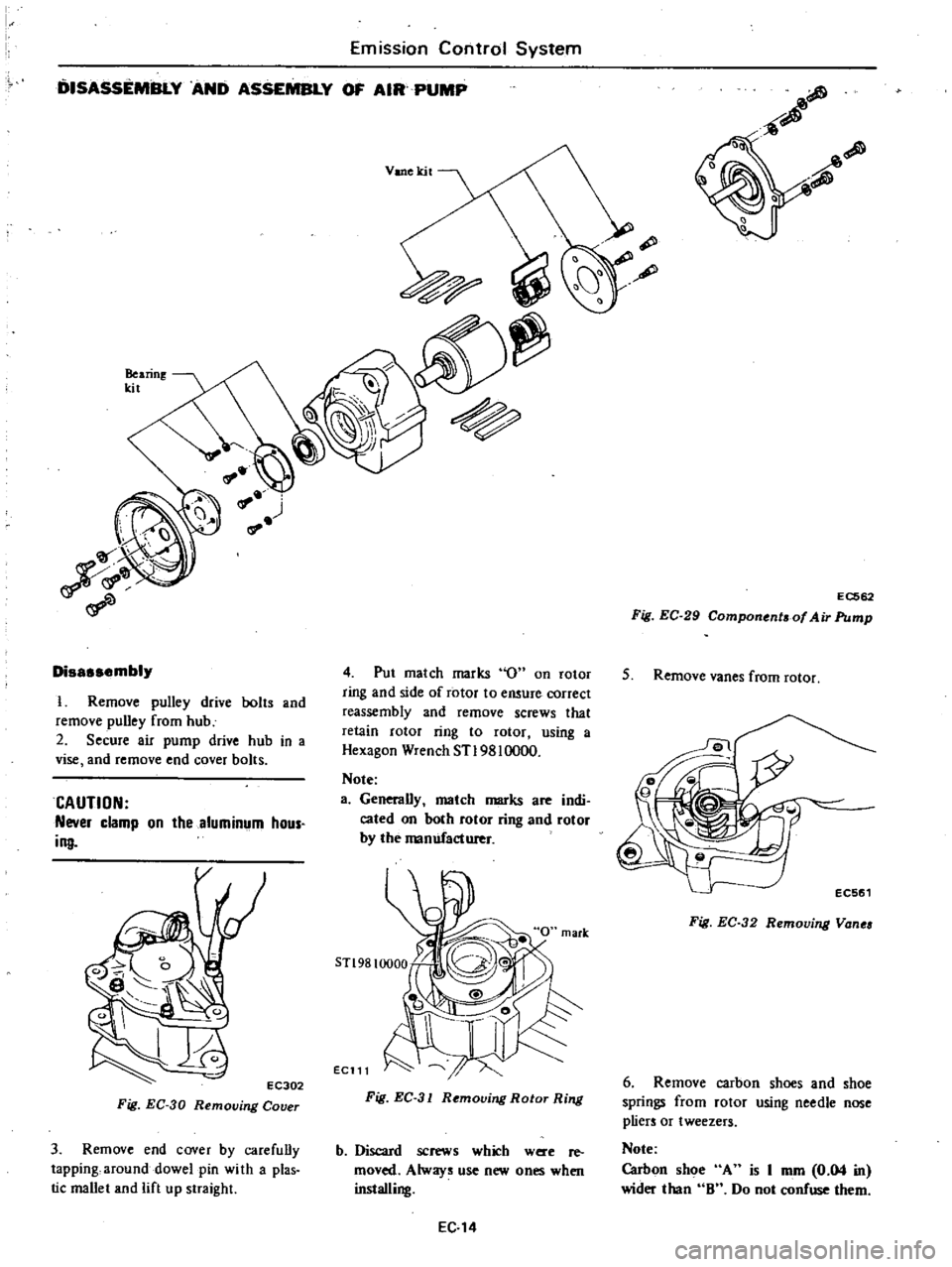
Disassembly
I
Remove
pulley
drive
bolts
and
remove
pulley
from
hub
2
Secure
air
pump
drive
hub
in
a
vise
and
remove
end
cover
bolts
CAUTION
Never
clamp
on
the
aluminum
hous
ing
EC302
Fig
EC
30
Removing
Cover
3
Remove
end
cover
by
carefuDy
tapping
around
dowel
pin
wi
th
a
plas
tic
mallet
and
lift
up
straight
Vane
kit
4
Put
match
marks
0
on
rotor
ring
and
side
of
rotor
to
ensure
correct
reassembly
and
remove
screws
that
retain
rotor
ring
to
rotor
using
a
Hexagon
Wrench
STl98l0000
Note
a
Generally
match
marks
are
indi
cated
on
both
rotor
ring
and
rotor
by
the
manufacturer
Ee111
Fig
EC
31
Removing
Rotor
Ring
b
Discard
screws
which
were
re
moved
Always
use
new
ones
when
installing
EC
14
EC562
Fig
EC
29
Component
of
Air
Pump
5
Remove
vanes
from
rotor
Fig
EC
32
Removing
Vanea
6
Remove
carbon
shoes
and
shoe
springs
from
rotor
using
needle
nose
pliers
or
tweezers
Note
Carbon
shoe
A
is
I
mm
0
04
in
wider
than
8
Do
not
confuse
them
Page 134 of 548
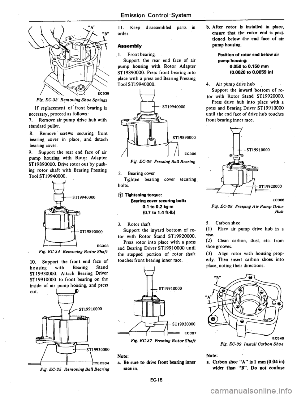
Fig
EC
33
R
moving
Shoe
Springs
If
replacement
of
fron
t
bearing
is
necessary
proceed
as
follows
7
Remove
air
pump
drive
hub
with
standard
puller
8
Remove
screws
securing
front
bearing
cover
in
place
and
detach
bearing
cover
9
Support
the
rear
end
face
of
air
pump
housing
with
Rotor
Adapter
STI
9890000
Drive
rotor
out
by
push
ing
rotor
shaft
with
Bearing
Pressing
Tool
STI
9940000
STl9940000
JJr
STl9890000
EC303
Fig
EC
34
Removing
Rotor
Shaft
10
Support
the
fron
t
end
face
of
housing
with
Bearing
Stand
STI9930000
Attach
Bearing
Driver
STI
9910000
to
front
bearing
on
the
inside
of
air
pump
housing
and
press
out
I
STl9910000
1
c
R
9930000
II
EC304
Fig
EC
35
R
mouing
Ball
B
aring
Emission
Control
System
II
Keep
disassembled
parts
in
order
Assembly
Front
bearing
Support
the
rear
end
face
of
air
pump
housing
with
Rotor
Adapter
STI
9890000
Press
front
bearing
into
place
with
a
press
and
Bearing
Pressing
Tool
STI
9940000
I
I
J
j
71
EC306
Fig
EC
36
Pre88ing
Ball
Bearing
2
Bearing
cover
T
ighten
bearing
cover
securing
bolts
@
Tightening
torque
Bearing
cover
securing
bolts
0
1
to
02
kg
m
0
7
to
1
4
ft
Ib
3
Rotor
shaft
Support
the
in
ard
bottom
of
ro
tor
with
Rotor
Staild
STI
9920000
Press
rotor
into
place
with
a
press
and
Bearing
Driver
STI9910000
until
the
stepped
portion
of
rotor
shaft
touches
front
bearing
inner
race
t
7
STl9910000
STl9920000
i
I
EC307
Fig
EC
37
Pressing
Rotor
Shaft
Note
a
Be
sure
to
drive
front
bearing
inner
race
in
EC
15
b
After
rotor
is
installed
in
place
ensure
that
the
rotor
end
is
posi
tioned
helow
the
end
face
of
air
pump
housing
Position
of
rotor
end
below
air
pump
housing
0
050
to
0
150
mm
0
0020
to
0
0059
in
4
Air
pump
drive
hub
Support
the
inward
bottom
of
ro
tor
with
Rotor
Stand
STI
9920000
Press
drive
hub
into
place
with
a
press
and
Bearing
Driver
STI99l0000
until
the
end
face
of
drive
hub
touches
front
bearing
inner
race
H
STl99
10000
EC30B
Fig
EC
38
Pre
sing
A
ir
Pump
Drive
Hub
5
Carbon
shoe
I
Place
air
pump
drive
hub
in
a
vise
2
Clean
carbon
dust
etc
from
shoe
grooves
3
Align
rotor
with
housing
prop
erly
Then
insert
carbon
shoes
into
place
noting
their
directions
EC5
0
Fig
EC
39
Install
Carbon
Sho
Note
a
Carbon
sh
A
is
I
mm
0
04
in
wider
than
B
Do
not
confuse