Electrical DATSUN 210 1979 Service Manual
[x] Cancel search | Manufacturer: DATSUN, Model Year: 1979, Model line: 210, Model: DATSUN 210 1979Pages: 548, PDF Size: 28.66 MB
Page 3 of 548
DATSUN
210
SERVICE
MANUAL
Model
8310
Series
T
OfOUoW
lTY
INISSAN
N
OIlCOIIO
NISSAN
MOTOR
CO
LTD
17
1
Ginza
6
Chome
Chuo
ku
Tokyo
104
Japan
QUICK
REFERENCE
INDEX
GENERAL
INFORMATION
GI
ENGINE
TUNE
UP
ET
ENGINE
MECHANICAL
EM
ENGINE
LUBRICATION
SYSTEM
EL
COOLING
SYSTEM
CO
ENGI
NE
FUEL
EF
EMISSION
CONTROL
SYSTEM
EC
ENGINE
ELECTRICAL
SYSTEM
EE
ENGINE
REMOVAL
INSTALLATION
ER
CLUTCH
CL
lMr
MANUAL
TRANSMISSION
MT
AUTOMATIC
TRANSMISSION
AT
H
PROPELLER
SHAFT
OIFFERENTlAL
CARRIER
PO
FRONT
AXLE
FRONT
SUSPENSION
FA
10
REAR
AXLE
REAR
SUSPENSION
RA
BRAKE
SYSTEM
BR
WHEEL
A
NO
TI
RE
WT
0
STEERING
SYSTEM
ST
ENGINE
CONTROL
FUEL
EXHAUST
SYSTEMS
FE
BOOY
BF
BOOY
ELECTRICAL
SYSTEM
BE
AIR
CONOITIONING
AC
Page 40 of 548
PRELIMINARY
CLEANING
AND
INSPECTION
Before
disassembling
engine
ob
serve
the
following
items
I
Prior
to
disassembling
check
outer
parts
for
sign
of
leak
past
their
gasketed
surfaces
2
Check
carburetor
and
fuel
pump
for
condition
fuel
hoses
for
deteriora
t
ion
cracks
or
otherwise
leakage
of
fuel
past
their
jointed
or
connected
surfaces
3
Wipe
dust
and
mud
off
engine
4
Inspect
outer
parts
for
visual
faults
and
broken
or
missing
parts
such
as
bolts
and
nuts
5
Check
piping
and
electrical
cir
cuits
for
deterioration
breakage
fittings
discontinuity
or
insulation
DISASSEMBLY
To
remove
engine
from
car
refer
to
Section
ER
for
Removal
1
Remove
starting
motor
then
re
move
transmission
from
engine
2
Remove
clutch
assembly
3
Remove
alternator
fan
belt
alter
nator
bracket
and
alternator
adjusting
bar
4
Remove
idler
pulley
air
pump
belt
and
idier
pulley
bracket
If
so
equipped
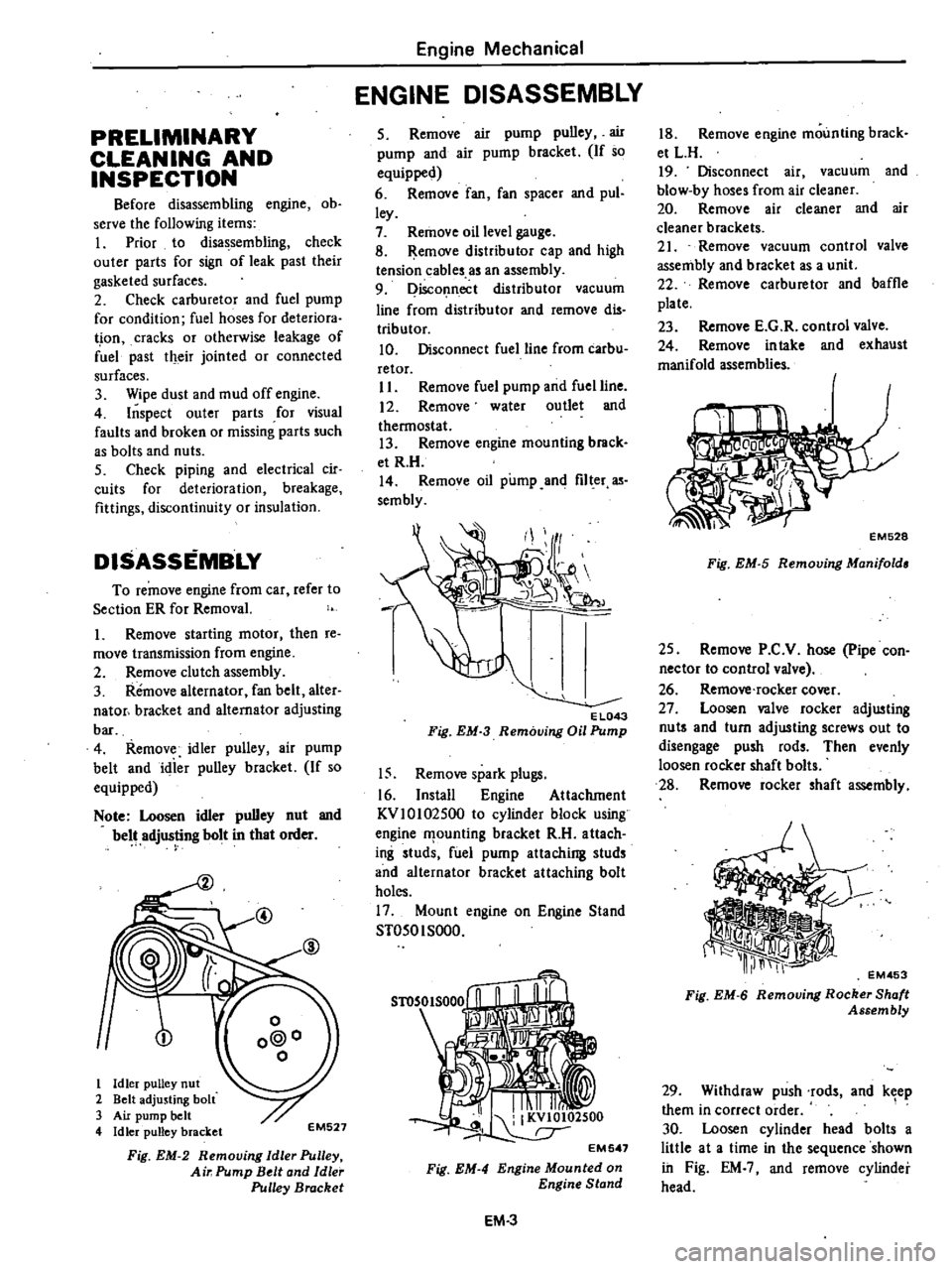
Note
Loosen
idler
pulley
nut
and
belt
adjusting
bolt
in
that
order
@
1
Idler
pulley
nut
2
Belt
adjusting
bolt
3
Air
pump
belt
4
Idler
pulley
bracket
EM527
Fig
EM
2
Removing
Idle
Pulley
Air
Pump
Belt
and
Idle
Pulley
Bracket
Engine
Mechanical
ENGINE
DISASSEMBLY
5
Remove
air
pump
pulley
air
pump
and
air
pump
bracket
If
so
equipped
6
Remove
fan
fan
spacer
and
pul
ley
7
Remove
oil
level
gauge
8
Remove
distributor
cap
and
high
tension
cables
as
an
assembly
9
Disconnect
distributor
vacuum
line
from
distributor
and
remove
dis
tributor
10
Disconnect
fuel
line
from
carbu
retor
II
Remove
fuel
pump
and
fuel
line
12
Remove
water
outlet
and
thermostat
13
Remove
engine
mounting
brack
et
R
H
14
Remove
oil
pump
and
filter
as
sembly
EL043
Fig
EM
3
Removing
Oil
Pump
15
Remove
spark
plugs
16
Install
Engine
Attachment
KVlOI02500
to
cylinder
block
using
engine
f1
ounling
bracket
R
H
attach
ing
studs
fuel
pump
attaching
studs
and
alternator
bracket
attaching
bolt
holes
17
Mount
engine
on
Engine
Stand
ST050I
SOOO
Fig
EM
4
EM
3
18
Remove
engine
mounting
brack
et
L
H
19
Disconnect
air
vacuum
and
blow
by
hoses
from
air
cleaner
20
Remove
air
cleaner
and
air
cleaner
brackets
21
Remove
vacuum
control
valve
assembly
and
bracket
as
a
unit
22
Remove
carburetor
and
baffle
plate
23
Remove
E
G
R
control
valve
24
Remove
intake
and
exhaust
manifold
assemblies
EM528
Fig
EM
5
Removing
Manifold
25
Remove
P
C
V
hose
pipe
con
nector
to
control
valve
26
Remove
rocker
cover
27
Loosen
valve
rocker
adjusting
nut
and
turn
adjusting
screws
out
to
disengage
push
rods
Then
evenly
loosen
rocker
shaft
bolts
28
Remove
rocker
shaft
assembly
EM453
Fig
EM
6
Removing
Rocker
Shaft
Assembly
29
Withdraw
push
rods
and
keep
them
in
correct
order
1
30
Loosen
cylinder
head
bolts
a
little
at
a
time
in
the
sequence
shown
in
Fig
EM
and
remove
cylinder
head
Page 115 of 548

Engine
fuel
TROUBLE
DIAGNOSES
AND
CORRECTIONS
In
the
following
table
the
symp
toms
and
causes
of
carburetor
troubles
and
remedies
for
them
are
listed
to
facilitate
quick
repairs
There
are
various
causes
of
engine
malfunctions
It
sometimes
happens
that
a
carburetor
which
has
no
fault
appears
to
have
some
problems
when
Condition
Probable
cause
Overflow
Dirt
accumulated
on
needle
valve
Fuel
pump
pressure
too
high
Needle
valve
improperly
seated
Excessive
fuel
consumption
Fuel
overflow
Slow
jet
too
large
on
each
main
jet
Main
air
bleed
clogged
Choke
valve
does
not
open
fully
Outlet
valve
seat
of
accelerator
pump
improper
Unked
opening
of
secondary
throttle
valve
opens
ioo
early
Power
shortage
Mainjels
clogged
Every
throttle
valve
Joes
not
open
fully
Idling
adjustment
incorrect
Fuel
filter
clo
ll
ed
Vacuum
jet
clogged
Air
cleaner
clogged
Diaphragm
damaged
Power
valve
operating
improperly
Improper
idling
Slow
jet
clogged
Every
throttle
valve
does
not
close
Secondary
throttle
valve
operating
im
properly
Throttle
valve
shafts
wom
Packing
between
manifold
carburetor
faulty
Manifold
carburetor
tightening
improper
Fuel
overflow
T
O
C
S
adjustment
incorrect
Vacuum
control
solenoid
damaged
Stuck
dash
pot
EF
30
acfuaJIy
theelectric
syslem
i
at
fatilt
Therefore
whenever
the
engine
is
mal
functioning
the
electrical
system
should
be
checked
fust
before
adjust
ing
carburetor
Corrective
action
Clean
needle
valve
Repair
pump
Replace
See
above
item
Replace
Clean
Adjust
Lap
Adjust
Clean
Adjust
Repair
Repair
Clean
Clean
Replace
Adjust
Clean
Adjust
Overhaul
and
clean
Replace
Replace
packing
Correct
tightening
See
the
first
item
Adjust
Replace
Replace
Page 148 of 548
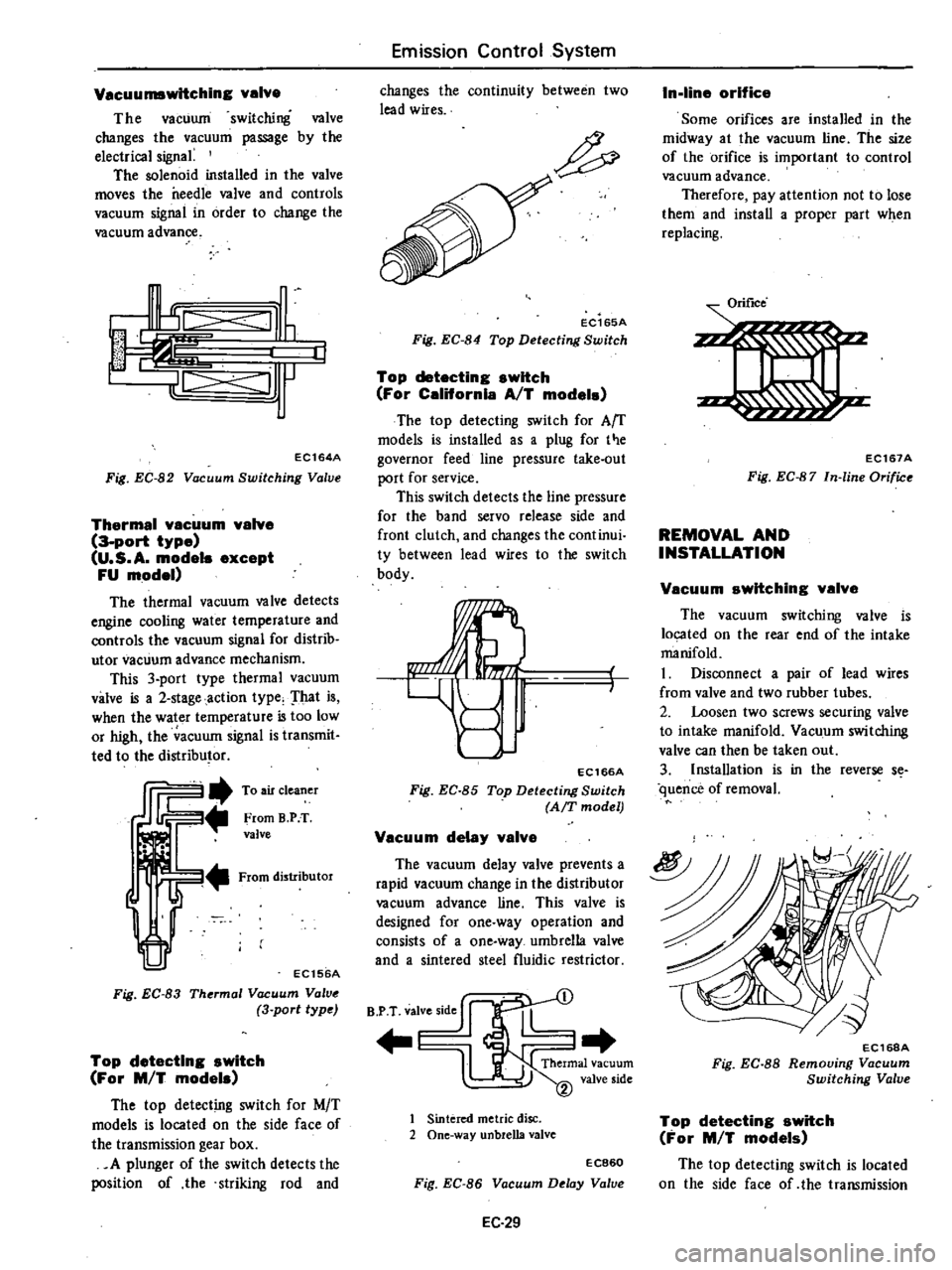
Vacuumswltching
valve
The
vacuum
switching
valve
changes
the
vacuum
passage
by
the
electrical
signa
The
solenoid
installed
in
the
valve
moves
the
needle
valve
and
controls
vacuum
signal
in
order
to
change
the
vacuum
advance
I
c
III
J
IL
jll
J
EC164A
Fig
EC
82
Vacuum
Switching
Valve
Thermal
vacuum
valve
3
port
type
U
S
A
modele
except
FU
model
The
thermal
vacuum
valve
detects
engine
cooling
water
temperature
and
controls
the
vacuum
signal
for
distrib
utor
vacuum
advance
mechanism
This
3
port
type
thermal
vacuum
valve
is
a
2
stage
action
type
That
is
when
the
water
temperature
is
too
low
or
high
the
acuum
signal
is
transmit
ted
to
the
distributor
ffi2
To
air
cleaner
From
B
PT
valve
From
distributor
EC156A
Fig
EC
83
Thermal
Vacuum
Valve
3
port
type
Top
detecting
switch
For
M
T
models
The
top
detecting
switch
for
M
T
models
is
located
on
the
side
face
of
the
transmission
gear
box
A
plunger
of
the
switch
detects
the
position
of
the
striking
rod
and
Emission
Control
System
changes
the
continuity
between
two
lead
wires
EC165A
Fig
EC
84
Top
Detecting
Switch
Top
detecting
switch
For
Celifornla
AfT
model
The
top
detecting
switch
for
Arr
models
is
installed
as
a
plug
for
t
e
governor
feed
line
pressure
take
out
port
for
service
This
switch
detects
the
line
pressure
for
the
band
servo
release
side
and
front
clutch
and
changes
the
continui
ty
between
lead
wires
to
the
switch
body
EC166A
Fig
EC
85
Top
Detecting
Switch
AfT
model
Vacuum
delay
valve
The
vacuum
delay
valve
prevents
a
rapid
vacuum
change
in
the
distributor
vacuum
advance
line
This
valve
is
designed
for
one
way
operation
and
consists
of
a
one
way
umbrella
valve
and
a
sintered
steel
fluidic
restrictor
B
P
T
valve
side
J
l
1
Sintered
metric
disc
2
One
way
unbreUa
valve
EC860
Fig
EC
86
Vacuum
Delay
Value
EC
29
In
line
orifice
Some
orifices
are
installed
in
the
midway
at
the
vacuum
line
The
size
of
the
orifice
is
important
to
control
vacuum
advance
Therefore
pay
attention
not
to
lose
them
and
install
a
proper
part
when
replacing
Orifice
EC167A
Fig
EC
87
In
line
Orifice
REMOVAL
AND
INSTALLATION
f
Vacuum
switching
valve
The
vacuum
switching
valve
is
located
on
the
rear
end
of
the
intake
manifold
I
Disconnect
a
pair
of
lead
wires
from
valve
and
two
rubber
tubes
2
Loosen
two
screws
securing
valve
to
intake
manifold
Vacuum
switching
valve
can
then
be
taken
out
3
Installation
is
in
the
reverse
s
quence
of
removal
EC16BA
Fig
EC
88
Removing
Vacuum
Switching
Valve
Top
detecting
switch
For
M
T
models
The
top
detecting
switch
is
located
on
the
side
face
of
the
transmission
Page 150 of 548
INSPECTION
Entire
system
U
S
A
MIT
models
except
FU
mo
el
1
Ensure
that
wiring
connectors
are
tight
in
pla
ce
2
Ensure
that
vacuum
hoses
are
properly
cof
1o
c
ed
to
their
positions
3
Ensure
that
distributor
vacuum
controller
properly
functions
4
Set
timing
light
and
start
engine
S
While
engine
cooling
water
tem
pefature
is
below
SOOC
I220F
check
function
of
system
as
follows
WARNING
To
protect
against
accidental
for
ward
surge
engage
parking
brake
firmly
while
above
check
is
being
made
I
Run
engine
and
keep
it
at
ap
proximately
1
600
rpm
2
Disengage
clutch
Shift
gears
in
top
3rd
then
neutral
positions
Read
spark
timing
in
respective
shift
posi
tions
The
system
is
properly
functioning
if
spark
timir
g
does
not
change
If
t
changes
check
thefmal
vacuum
valve
3
port
type
Note
Ensure
that
thermal
vacuum
wIve
is
closed
when
cooling
water
i
below
5
to
lSoC
41
to
640F
or
above
SO
to
630C
122
to
14S0F
I
6
After
the
engine
has
been
warmed
up
sufficiently
check
the
function
of
the
system
again
in
the
I
Same
manner
The
system
is
properly
functioning
if
spark
iimin
advances
in
top
posi
tion
If
not
check
thefmal
vacuum
valve
control
circuit
or
vaeu
um
switching
valve
Entire
system
FU
model
and
Canada
MIl
models
I
Ensure
that
wiri
lg
connectors
are
tight
in
place
Emission
Control
System
2
Ensure
that
vacuum
hoses
are
properly
connected
to
their
positions
3
Ensure
that
distributor
vacuum
controller
properly
fu
ctions
4
Set
timing
light
WARNING
To
protect
against
accidental
for
ward
surge
engage
parking
brake
firmly
while
above
check
is
being
made
5
Run
engine
and
keep
it
at
ap
proximately
1
600
1
m
6
Disengage
clutch
Shift
gears
in
4th
5th
ihen
neutral
positions
Read
spark
timing
in
respective
shift
posi
tions
The
system
is
properly
functioning
if
spark
timing
advances
in
top
gear
position
If
spark
timing
does
not
vary
at
all
in
tests
des
rilied
in
step
6
above
check
control
circuit
or
vacuum
switching
valve
Entire
system
California
AIT
models
I
Ensure
th
t
wiring
connectors
are
tight
in
place
2
Ensure
that
vacuum
hoses
are
properly
coIDwcted
to
thejr
positions
3
Ensure
that
distributor
vacuum
controller
function
s
properly
4
Set
timing
light
and
staft
engine
S
While
engine
cooling
water
tem
perature
is
below
SOOC
1220F
check
the
function
of
the
system
as
follows
WARNING
To
protect
againSt
accidental
for
ward
surge
engage
parking
brake
firmly
while
above
check
is
being
made
I
Run
engine
and
keep
it
at
ap
proximately
1
600
rpm
at
P
range
2
Make
a
short
circuit
between
the
specified
two
terminals
at
function
te
t
connector
EC31
The
entire
system
except
for
the
top
switch
is
properly
functioning
if
spark
timing
does
not
change
If
it
changes
check
the
thermal
vacuum
valve
3
pori
type
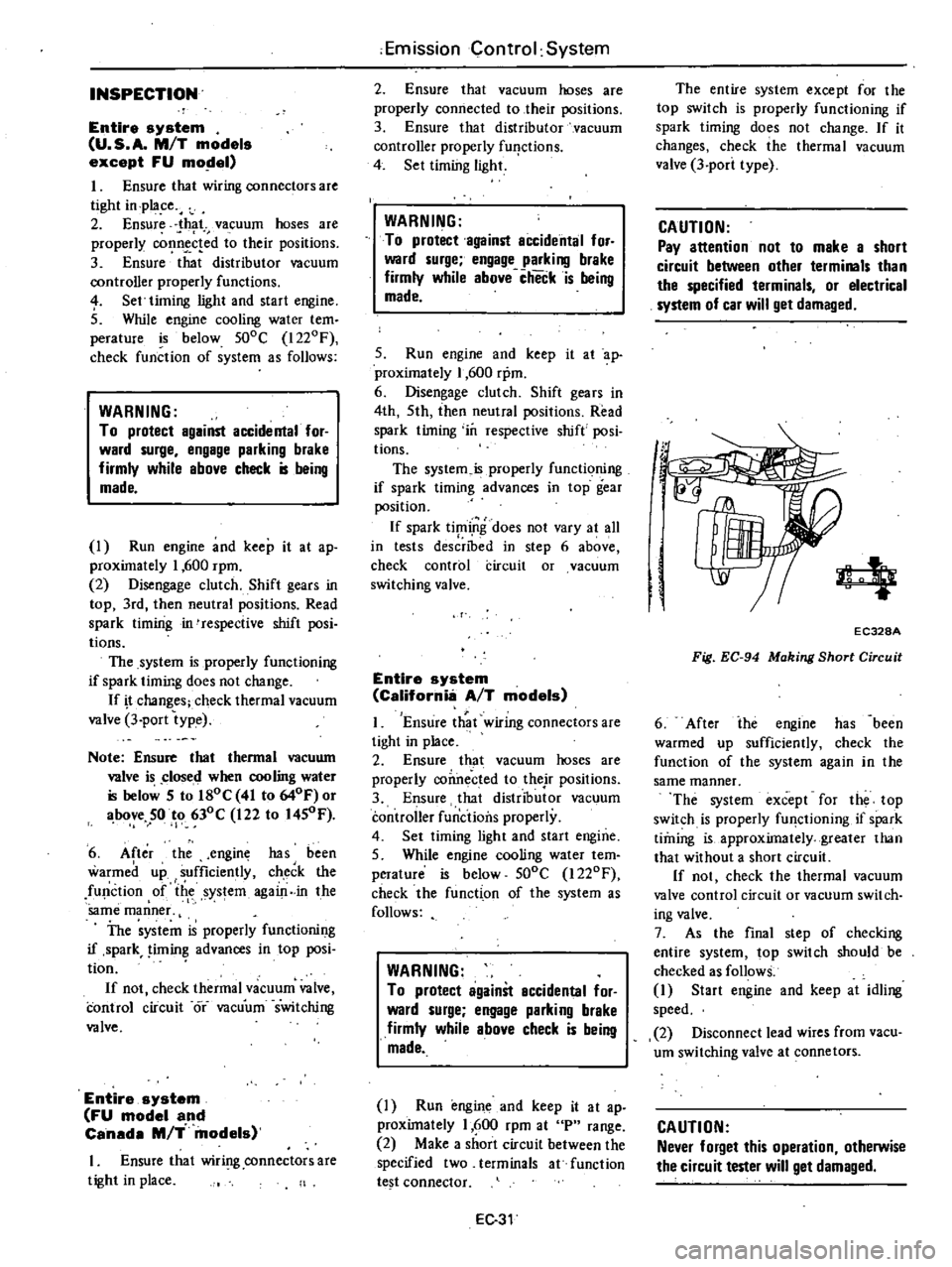
CAUTION
Pay
attention
not
to
make
a
short
circuit
between
other
terminals
than
the
specified
terminals
or
electrical
system
of
car
will
get
damaged
4
EC328A
Fig
EC
94
Making
Short
Circuit
6
After
ihe
engine
has
been
warmed
up
sufficiently
check
the
function
of
the
system
again
in
the
same
manner
The
system
except
for
the
top
switch
is
properly
fU
lctioning
if
spark
timing
is
approximately
greater
than
that
without
a
short
circuit
If
not
check
the
thermal
vacuum
valve
control
circuit
or
vacuum
switch
ing
valve
7
As
the
final
step
of
checking
entire
system
top
switch
should
be
checked
as
follows
1
Start
engine
and
keep
at
idling
speed
2
Disconnect
lead
wires
from
vacu
um
switching
valve
at
connetors
CAUTION
Never
forget
this
operation
otherwise
the
circuit
tester
will
get
damaged
Page 159 of 548
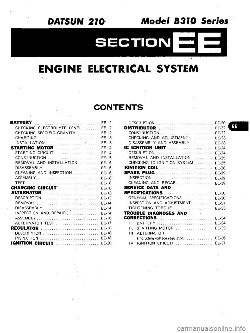
DATSUN
210
Model
8310
Series
SECTIONEE
ENGINE
ELECTRICAL
SYSTEM
CONTENTS
BATTERY
CHECKING
ELECTROLYTE
LEVEL
CHECKING
SPECIFIC
GRAVITY
CHARGING
INSTALLATION
STARTING
MOTOR
STARTING
CIRCUIT
CONSTRUCTION
REMOVAL
AND
INSTALLATION
DISASSEMBL
Y
CLEANING
AND
INSPECTION
ASSEMBL
Y
TEST
CHARGING
CIRCUIT
ALTERNATOR
DESCRIPTION
REMOVAL
DISASSEMBLY
INSPECTION
AND
REPAIR
ASSEMBLY
ALTERNATOR
TEST
REGULATOR
DESCRIPTION
INSPECTION
IGNITION
CIRCUIT
EE
2
EE
2
EE
2
EE
3
EE
3
EE
4
EE
4
EE
5
EE
6
EE
6
EE
6
EE
8
EE
8
EE
10
EE
13
EE
13
EE
14
EE
14
EE
14
EE
16
EE
17
EE
1B
EE
18
EE
18
EE
20
DESCRIPTION
DISTRIBUTOR
CONSTRUCTION
CHECKING
AND
ADJUSTMENT
I
ISASSEMBL
Y
AND
ASSEMBLY
IC
IGNITION
UNIT
DESCRIPTION
REMOVAL
AND
INSTALLATION
CHECKING
IC
IGNITION
SYSTEM
IGNITION
COIL
SPARK
PLUG
INSPECTION
CLEANING
AND
REGAP
SERVICE
DATA
AND
SPECIFICATIONS
GENERAL
SPECIFICATIONS
INSPECTION
AND
ADJUSTMENT
TIGHTENING
TORQUE
TROUBLE
DIAGNOSES
AND
CORRECTIONS
I
BATTERY
II
STARTING
MOTOR
III
ALTERNATOR
Including
voltage
regulator
IV
IGNITION
CIRCUIT
EE
20
EE
22
EE
22
EE
23
EE
23
EE
24
EE
24
EE
25
EE
25
EE
28
EE
29
EE
29
EE
29
EE
30
EE
30
EE
31
EE
33
EE
34
EE
34
EE
35
EE
36
EE
37
Page 160 of 548
WARNING
Never
touch
positive
and
negative
terminals
at
the
same
time
with
are
hands
Th
l
Il
d
result
in
injury
CHECKING
ELECTROLYTE
LEVEL
Remove
six
vent
plugs
and
check
for
electrolyte
level
in
each
cell
If
necessary
pour
distilled
water
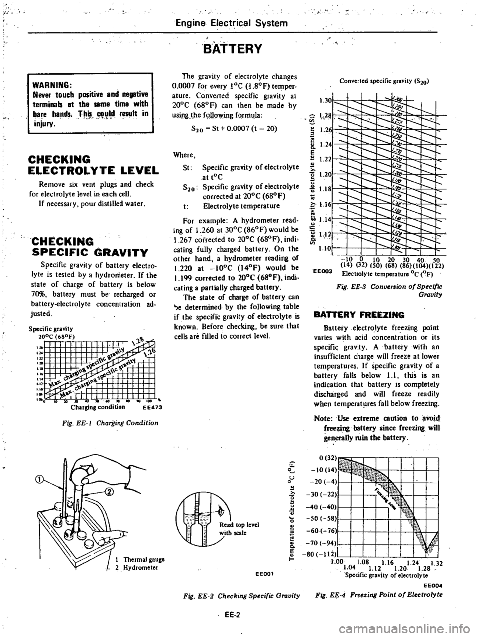
CHECKING
SPECIFIC
GRAVITY
Specific
gravity
of
battery
electro
lyte
is
tested
by
a
hydrometer
If
the
state
of
charge
of
battery
is
below
70
battery
must
be
recharged
or
battery
electrolyte
concentration
ad
justed
EE473
Fig
EE
l
Charging
Condition
Engine
Electrical
System
BATTERY
The
gravity
of
electrolyte
changes
0
0007
for
every
loe
I
80F
temper
ature
Converted
specific
gravity
at
200e
680F
can
then
be
made
by
using
the
following
form
la
S20
St
0
0007
t
20
Where
St
Specific
gravity
of
electrolyte
at
tOe
S20
Specific
gravity
of
electrolyte
corrected
al
200e
680
F
t
Electrolyte
temperature
For
example
A
hydrometer
read
ing
of
1
260
at
300e
860F
would
be
1
267
corrected
to
200e
680F
indi
cating
fully
charged
battery
On
the
olher
hand
a
hydrometer
reading
of
1
220
at
lOoe
I40F
would
be
I
199
corrected
to
200e
680F
indi
cating
a
partially
charged
battery
The
state
of
charge
of
battery
can
e
determined
by
the
following
table
if
the
specific
gravity
of
electrolyte
is
known
Before
checking
be
sure
that
cells
are
filled
to
correct
level
Converted
specific
gravity
S20
l
301
l
Z
L2
I
1
2
I
Ii
8
1
24
E
1
22
2
t
2e
u
1
18
c
i
1
161
1
141
2
1
12
Q
1
10
I
to
0
to
20
30
40
50
14
32
50
68
86
104
122
EEOO3
Electrolyte
temperature
Oc
OF
Fig
EE
3
Conversion
of
Specific
Gravity
BATTERY
FREEZING
Battery
electrolyte
freezing
point
varies
with
acid
concentration
or
its
specific
gravity
A
battery
with
an
insufficient
charge
will
freeze
al
lower
temperatures
If
specific
gravity
of
a
battery
falls
below
1
I
this
is
an
indication
that
battery
is
completely
discharged
and
will
freeze
readily
when
temperat
res
fall
below
freezing
Note
Use
extreme
caution
to
avoid
freezing
battery
since
freezing
will
generally
ruin
the
battery
1
u
B
I
r
eleYel
60
76
Ji
I
k
E
I
I
d
8
70
94
80
112
I
I
f
1
Thermal
gauze
1
00
1
08
1
16
1
24
1
32
2
Hydrometer
1
04
1
12
1
20
1
28
EE001
Specific
gravity
of
electrolyte
EE004
Fig
EE
2
Checking
Specific
Gravity
Fig
EE
4
Freezing
Point
of
Electrolyte
EE
2
Page 161 of 548
CHARGING
If
electrolyte
level
is
satisfactory
battery
must
be
charged
when
electro
lyte
gravity
reading
falls
below
1
20
or
1
22
NS70
If
battery
on
car
is
quick
charged
to
bring
it
up
to
full
charge
the
operation
should
be
carried
out
with
negative
cable
removed
Prior
to
charging
corroded
termi
nals
should
be
cleaned
with
a
brush
and
common
baking
soda
solution
In
addition
the
following
items
should
be
observed
while
battery
is
being
Engine
Electrical
System
charged
I
Be
sure
that
electrolyte
level
is
above
top
of
each
plate
2
Keep
removed
plugs
in
a
safe
place
3
Do
not
allow
electrolyte
tempera
ture
to
go
over
4SoC
1130F
4
After
charging
check
to
be
cer
tain
that
specific
gravity
does
not
exceed
maximum
charging
specific
gravity
at
20
C
680F
Correction
can
be
made
by
adding
distilled
water
into
cells
as
necessary
5
Keep
battery
away
from
open
EE
3
flame
while
it
is
being
charged
6
After
all
vent
plugs
have
been
tightened
clean
all
sprayed
electrolyte
off
upper
face
of
battery
INSTALLATION
1
InstaU
and
tighten
clamps
secure
ly
2
After
clamps
have
been
tightened
clean
battery
cable
terminals
and
apply
grease
to
retard
formation
of
corrosion
Page 162 of 548
Engine
Electrical
System
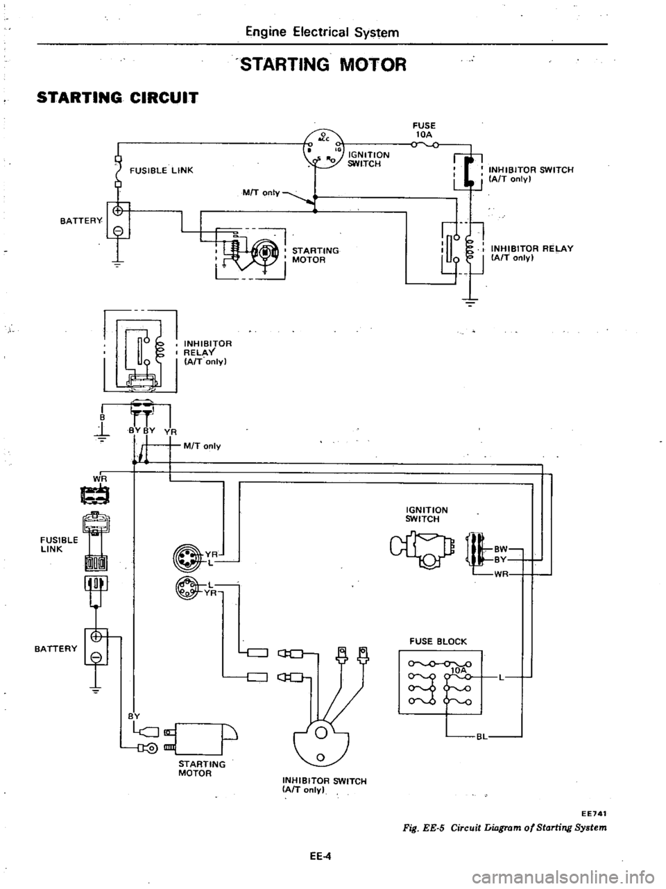
STARTING
MOTOR
STARTING
CIRCUIT
FUSIBLE
LINK
FUSE
lOA
INHIBITOR
SWITCH
LJ
J
IAfT
onlv
I
IGNITION
SWITCH
7
MIT
OnIY
STARTING
I
MOTOR
L
u
l
l
lJ
INHIBITOR
RELAY
IAfT
only
BATTERY
f
1J
INHIBITOR
RELAY
I
I
A
T
onlyl
I
B
l
I
BY
BY
VA
j
M
T
only
I
J
ti
FUSIBLE
LINK
On
IGNITION
SWITCH
BATTERY
YR
L
L
YR
tl
WR
FUSE
BLOCK
c
J
GO
c
J
C
lOA
S
L
BY
p
BL
STARTING
MOTOR
INHIBITOR
SWITCH
IAIT
only
EE741
Fig
EE
5
Circuit
Liagrom
of
Starting
System
EE4
Page 163 of 548
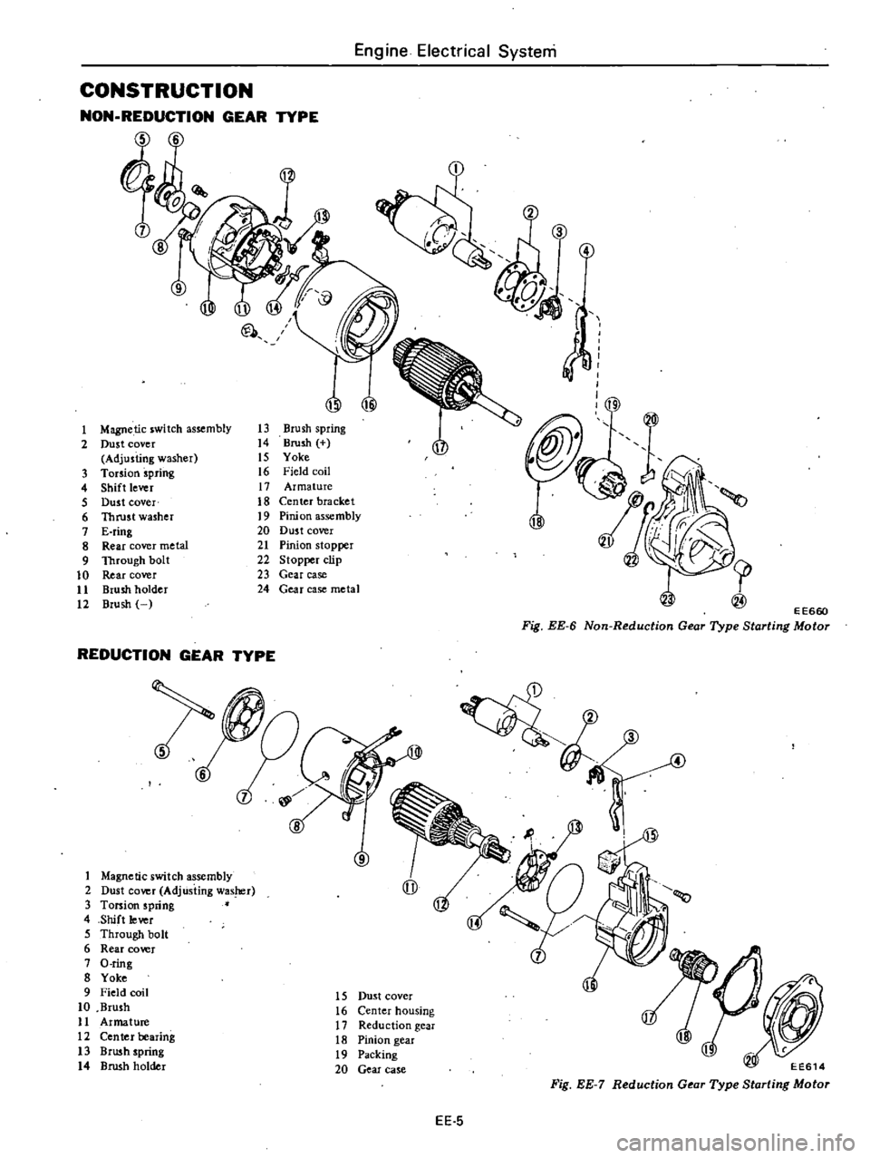
CONSTRUCTION
NON
REDUCTION
GEAR
TYPE
6
00
1
Magnetic
switch
assembly
2
Dust
cover
Adjusting
washer
3
Torsion
spring
4
Shift
lever
5
Dust
cover
6
Thrust
washer
7
E
ring
8
Rear
cover
metal
9
Through
bolt
10
Rear
cover
11
Brush
holder
12
Brush
U
Ul
@
13
Brush
spring
14
Brush
IS
Yoke
16
Field
coil
17
Armature
18
Center
bracket
19
Pinion
assembly
20
Dus
t
cover
21
Pinion
stopper
22
Stopper
clip
23
Gear
case
24
Gear
case
metal
REDUCTION
GEAR
TYPE
1
Magnetic
switch
assembly
2
Dust
cover
AdjUsting
was
r
3
Torsion
spring
4
Shift
lever
5
Through
bolt
6
Rear
cover
7
O
ring
8
Yoke
9
Field
coil
10
Brush
11
Armature
12
Ceo
tel
bearing
13
Brush
spring
14
Brush
holder
6
8
Engine
Electrical
Systeni
3
@
1
E
E660
Fig
EE
6
Non
Reduction
Gear
Type
Starting
Motor
4
4
15
Dust
cover
16
Center
housing
17
Reduction
gear
18
Pinion
gear
19
Packing
20
Gear
case
EE614
Fig
EE
7
Reduction
Gear
Type
Starting
Motor
EE
5