ECO DATSUN PICK-UP 1977 Service Manual
[x] Cancel search | Manufacturer: DATSUN, Model Year: 1977, Model line: PICK-UP, Model: DATSUN PICK-UP 1977Pages: 537, PDF Size: 35.48 MB
Page 424 of 537

Engine
Control
Fuel
Exhaust
Systems
I
Wipe
clean
all
the
contact
por
tions
of
tube
joints
allow
them
to
dry
thoroughly
2
Temporarily
mount
in
place
muffler
assembly
as
an
assembled
unit
on
the
vehicle
3
Insert
front
tube
until
it
touches
emboss
m
b
nlfrnnjj
mm
lJ
Ij
@L
J
FE263
Fig
FE
ll
Exhawt
tube
connection
4
Torque
nut
securing
the
male
and
female
tubes
at
the
connection
Tightening
torque
is
1
6
to
2
0
kg
m
12
to
14
ft
lb
5
Squeeze
approximately
5
CC
0
31
cu
in
of
sealant
into
injection
from
sealant
tube
See
Figure
FE
12
Sealant
tube
polyethylene
Injector
Fig
FE
IO
Exhaust
sealant
kit
Be
sure
to
place
cap
back
to
sealant
tube
since
sealant
will
dry
Approximately
5
cc
0
31
Cll
in
FE1l1
Fig
FE
12
Squeezing
sealant
to
injec
tor
6
Position
nozzle
of
injector
to
the
guide
and
press
it
there
firmly
Inject
sealant
slowly
until
sealant
begins
to
flow
out
of
the
slit
of
tube
This
indicates
that
the
bead
requires
no
further
sealant
Excessive
sealant
can
cause
a
clogged
tube
See
Figure
FE
13
After
injecting
wash
injector
thoroughly
in
clean
water
to
remove
all
traces
of
sealant
FE191
Fig
FE
13
Injecting
sealant
FE
9
7
Start
engine
and
let
it
idle
slowly
for
ten
minutes
minimum
to
hilfden
sealant
with
the
heat
of
exhaust
gas
8
Check
the
condition
of
sealant
before
driving
the
vehicle
It
is
also
essential
that
the
vehicle
should
not
be
accelerated
sharply
for
20
to
30
minutes
subsequent
to
this
operation
Noles
a
The
sealant
should
be
used
within
guaranty
term
indicated
on
the
kit
case
b
Exposure
of
sealant
to
the
skin
may
cause
a
rash
Wash
sealant
off
the
skin
with
water
c
Do
not
keep
the
sealant
tube
in
a
place
where
the
ambient
tempera
ture
is
above
400C
I040F
A
sealant
hardened
above
4QoC
I040F
cannot
be
used
The
most
suitable
storage
temperature
is
from
15
to
350C
59
to
950F
If
sealant
becomes
hardened
because
of
low
temperatures
wann
the
sealant
tube
with
lukewarm
water
until
the
sealant
is
softened
Do
not
warm
tube
at
a
temperature
over
400C
1040F
for
a
long
time
d
Thoroughly
read
the
instruction
sheet
furnished
with
the
kit
before
using
the
sealant
i
Page 426 of 537
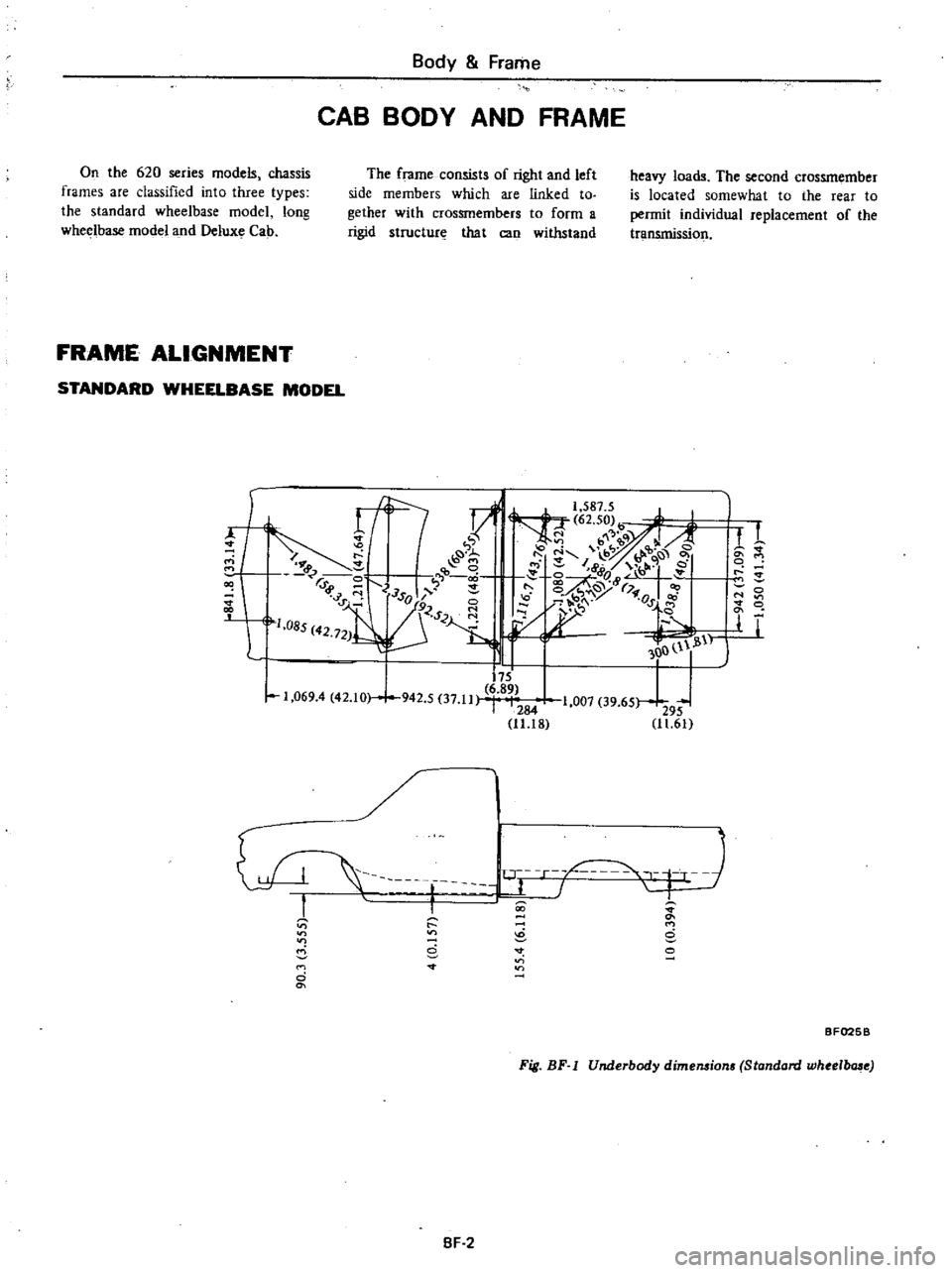
Body
Frame
CAB
BODY
AND
FRAME
On
the
620
series
models
chassis
frames
are
classified
into
three
types
the
standard
wheelbase
model
long
wheelbase
model
and
Deluxe
Cab
The
frame
consists
of
right
and
left
side
members
which
are
linked
to
gether
with
crossmembers
to
form
a
rigid
structure
that
can
withstand
heavy
loads
The
second
crossmember
is
located
somewhat
to
the
rear
to
permit
individual
replacement
of
the
transmissiol
FRAME
ALIGNMENT
STANDARD
WHEELBASE
MODEL
f
r1
1
587
5
J
I
1
X
62
50
I
b
q
J
A
1
7
I
b
9
9
8
I
1
e
t
r
0
ij
e
6
rd
r
r
1sol
1
1
9ClS
1
085
42
721
Cl
H
1
I
11
OO
l
1
i11
175
6
89
1
069
4
42
10
942
5
37
11
1007
39
65
I
284
295
11
18
11
61
00
d
M
o
8
r
r
c
8
o
r
T
L
BF025B
Fig
BF
I
Underbody
dime1l8ion
Standard
whee
b
e
SF
2
Page 434 of 537
REMOVAL
AND
INSTALLATION
I
Remove
hood
lock
male
by
re
moving
two
attaching
bolts
2
To
remove
hood
lock
female
first
remove
radiator
grille
Back
off
two
bolts
securing
hood
lock
female
in
position
Hood
lock
female
can
now
be
taken
out
3
Remove
two
bolts
attaching
hood
lock
handle
assembly
to
dash
side
paneL
Disconnect
cable
at
hood
lock
female
and
remove
cable
clamps
Pull
cable
out
into
cab
4
To
install
hood
lock
male
and
female
reverse
removal
procedure
Mter
installation
check
to
insure
that
they
are
properly
aligned
5
To
install
hood
lock
handle
as
sembly
reverse
steps
observing
the
following
notes
I
Check
to
be
certain
that
cable
clamps
are
tight
and
secure
2
Install
hood
lock
handle
bracket
in
place
by
using
two
of
four
holes
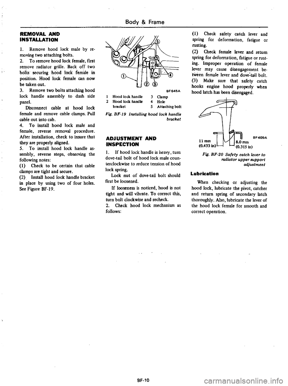
See
Figure
BF
19
Body
Frame
@
1
Hood
tock
handle
2
Hood
lock
handle
bracket
BF645A
3
Clamp
4
Hole
5
Attaching
bolt
Fig
BF
19
1MtalIing
hood
lock
handle
brocket
ADJUSTMENT
AND
INSPECTION
I
If
hood
lock
handle
is
heavy
turn
dove
tail
bolt
of
hood
lock
male
coun
terclockwise
to
reduce
tension
of
hood
lock
spring
Lock
nut
of
dove
tail
bolt
should
fust
be
loosened
If
looseness
is
noticed
hood
is
not
tight
and
will
vibrate
To
correct
this
turn
bolt
clockwise
and
recheck
2
Check
hood
lock
mechanism
as
follows
BF
10
I
Check
safety
catch
lever
and
spring
for
deformation
fatigue
or
rusting
2
Check
female
lever
and
return
spring
for
deformation
fatigue
or
rust
ing
Improper
operation
of
female
lever
may
cause
disengagement
be
tween
female
lever
and
dove
tail
bolt
3
Make
sure
that
safety
catch
hooks
engine
hood
properly
when
hood
latch
has
been
disengaged
0l
11
mm
I
nun
BF409A
0
433
in
0
3t5
in
Fig
BF
20
Safety
catch
lever
to
radiator
upper
support
acVu5tment
Lubrication
When
checking
or
adjusting
the
hood
lock
lubricate
the
pivot
catcher
and
return
spring
of
secondary
latch
thoroughly
Also
lubricate
the
lever
of
the
hood
lock
female
for
smooth
and
correct
operation
Page 442 of 537
Body
Frame
INTERIOR
TRIM
AND
CENTER
CONSOLE
HEADLINING
DESCRIPTION
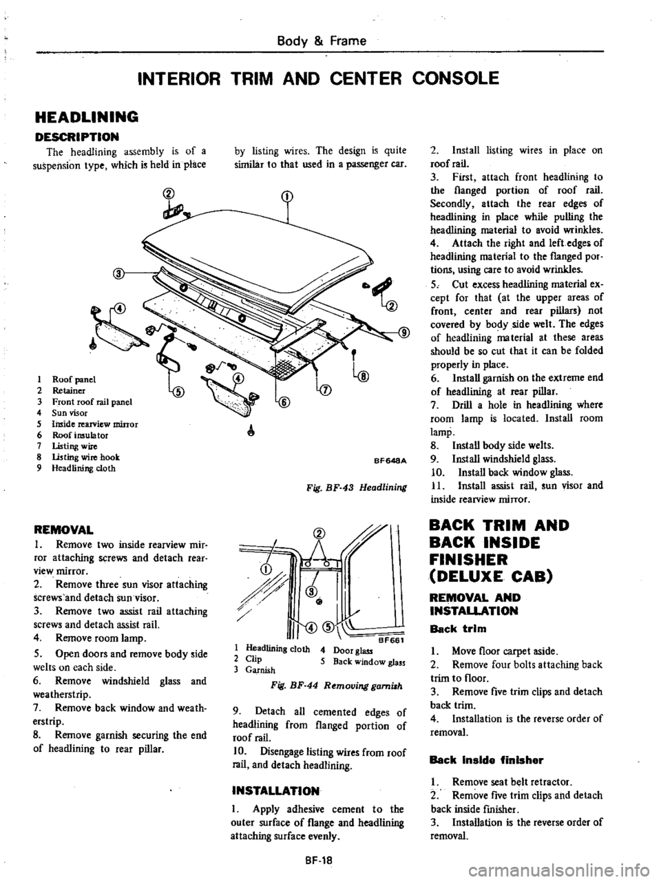
The
headlining
assembly
is
of
a
suspension
type
which
is
held
in
place
ct
I
2
3
4
5
6
7
8
9
REMOVAL
1
Remove
two
inside
rearview
mir
ror
attaching
screws
and
detach
rear
view
mirror
2
Remove
three
sun
visor
attaching
screws
and
detach
sun
visor
3
Remove
two
assist
rail
attaching
screws
and
detach
assist
rail
4
Remove
room
lamp
5
Open
doors
and
remove
body
side
welts
on
each
side
6
Remove
windshield
glass
and
weatherstrip
7
Remove
back
window
and
weath
erstrip
8
Remove
garnish
securing
the
end
of
headlining
to
rear
pillar
by
listing
wires
The
design
is
quite
similar
to
that
used
in
a
passenger
car
A
BF648A
Fig
BF
43
Headlining
CD
r
h
i
r
J
I
I
I
II
CID
BF661
1
Headlining
cloth
4
Door
glass
2
Clip
5
Back
window
glass
3
Garnish
Fig
BF
44
Removing
gami8h
9
Detach
all
cemented
edges
of
headlining
from
flanged
portion
of
roof
rail
10
Disengage
listing
wires
from
roof
rail
and
detach
headlining
INSTALLATION
I
Apply
adhesive
cement
to
the
outer
surface
of
flange
and
headlining
attaching
surface
evenly
8F
18
2
Install
listing
wires
in
place
on
roof
rail
3
First
attach
front
headlining
to
the
flanged
portion
of
roof
rail
Secondly
attach
the
rear
edges
of
headlining
in
place
while
pulling
the
headlining
material
to
avoid
wrinkles
4
Attach
the
right
and
left
edges
of
headlining
material
to
the
flanged
por
tions
using
care
to
avoid
wrinkles
5
Cut
excess
headlining
material
ex
cept
for
that
at
the
upper
areas
of
front
center
and
rear
pillars
not
covered
by
body
side
welt
The
edges
of
headlining
ma
terial
at
these
areas
should
be
so
cut
that
it
can
be
folded
properly
in
place
6
Install
garnish
on
the
extreme
end
of
headlining
at
rear
pillar
7
Drill
a
hole
in
headlining
where
room
lamp
is
located
Install
room
lamp
8
Install
body
side
welts
9
Install
windshield
glass
10
Install
back
window
glass
11
Install
assist
rail
sun
visor
and
inside
rearview
mirror
BACK
TRIM
AND
BACK
INSIDE
FINISHER
DELUXE
CAB
REMOVAL
AND
INSTALLATION
Back
trim
I
Move
floor
carpet
aside
2
Remove
four
bolts
attaching
back
trim
to
floor
3
Remove
five
trim
clips
and
detach
back
trim
4
Installation
is
the
reverse
order
of
removal
Back
Inside
finisher
I
Remove
seat
belt
retractor
2
Remove
five
trim
clips
and
detach
back
inside
fmisher
3
Installation
is
the
reverse
order
of
removal
Page 447 of 537
DESCRIPTION
Cables
are
covered
with
color
coded
vinyl
for
easy
identification
In
the
wiring
diagram
colors
are
indicated
by
one
or
two
alphabetical
letters
It
is
recommended
that
the
battery
be
disconnected
before
performing
any
electrical
service
other
than
bulb
or
fuse
replacement
In
addition
to
fuses
a
fusible
link
has
been
installed
to
protect
wiring
The
fusible
link
functions
almost
the
same
as
a
fuse
though
its
eharac
teristics
are
slightly
different
than
normal
fuses
CABLE
COLORS
Cable
colors
are
indicated
by
one
or
two
alphabetical
letters
B
Black
Be
Brown
G
Green
L
Blue
Lg
Light
green
R
Red
W
White
Y
Yellow
The
main
cable
is
generally
coded
with
a
single
color
The
others
are
coded
with
a
two
tone
color
as
follows
BW
Black
with
white
stripe
gR
Light
green
with
red
stripe
INSPECTION
Inspect
all
electrical
circuits
refer
ring
to
wiring
or
circuit
diagrams
Circuits
should
be
tested
for
conti
nuity
or
short
circuit
with
a
conven
tional
test
lamp
or
low
reading
volt
meter
Before
inspection
of
circuit
ensure
that
I
Each
electrical
component
part
or
cable
is
securely
fastened
to
its
con
nector
or
terminal
2
Each
connection
is
firmly
in
place
and
free
from
rust
and
dirt
3
No
cable
covering
shows
any
evidence
of
cracks
deterioration
or
other
damage
4
Each
terminal
is
at
a
safe
distance
away
from
any
adjacent
metal
parts
5
Each
cable
is
fastened
to
its
proper
connector
or
terminal
Body
Electrical
System
BODY
ELECTRICAL
WIRING
6
Each
grounding
bolt
is
firmly
pbnted
7
Wiring
is
kept
away
from
any
adjacent
parts
with
sharp
edges
or
high
temperature
parts
such
as
exhaust
pipe
8
Wiring
is
kept
away
from
any
rotating
or
working
parts
fan
pulley
fan
belt
etc
9
Cables
between
ftxed
portions
and
moving
parts
are
long
enough
to
withstand
shocks
and
vibratory
forces
Notes
a
Before
starting
to
inspect
and
repair
any
part
of
electrical
system
or
other
parts
which
may
lead
to
a
short
circuit
disconnect
cables
at
battery
terminals
as
follows
Disconnect
cable
at
negative
terminal
and
then
disconnect
cable
at
positive
terminal
Before
connecting
cables
to
battery
terminal
be
sure
to
clean
terminals
with
a
rag
Fasten
cable
at
positive
terminal
and
then
ground
cable
at
negative
terminal
Apply
grease
to
top
of
these
terminals
to
prevent
rust
from
developing
on
them
b
Never
use
a
screwdriver
or
senrice
tool
to
conduct
a
continuity
test
Use
test
leads
c
Never
ground
an
open
circuit
or
circuits
under
no
load
Use
a
test
lamp
12V
3W
or
circuit
tester
as
a
load
FUSE
AND
FUSIBLE
LINK
DESCRIPTION
The
fuse
and
fusible
link
are
protec
tive
devices
used
in
an
electrical
cir
cuit
When
current
increases
beyond
rated
amperage
fusible
metal
melts
and
the
circuit
is
broken
BE
2
MAINTENANCE
INSTRUCTIONS
Fuse
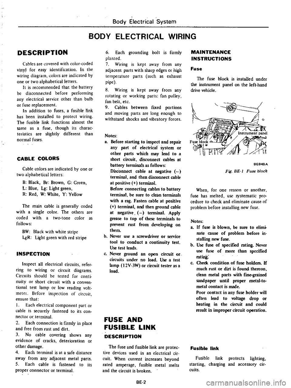
The
fuse
block
is
installed
under
the
instrument
panel
on
the
left
hand
drive
vehicle
BE848A
Fig
BE
1
Fuse
block
When
for
one
reason
or
another
fuse
has
melted
use
systematic
pro
cedure
to
check
and
eliminate
cause
of
problem
before
installing
new
fuse
Notes
a
If
fuse
is
blown
be
sure
to
elimi
nate
cause
of
problem
before
in
stalling
new
fuse
b
Use
fuse
of
specified
rating
Never
use
fuse
of
more
than
specified
rating
Co
Check
condition
of
fuse
holders
If
much
rust
or
dirt
is
found
thereon
clean
metal
parts
with
fine
grained
sandpaper
until
proper
metal
to
metal
contact
is
made
Poor
contact
in
any
fuse
holder
will
often
lead
to
voltage
drop
or
heating
in
the
circuit
and
could
result
in
improper
circuit
operation
Fusible
link
Fusible
link
protects
lighting
starting
charging
and
accessory
cir
cuits
Page 461 of 537
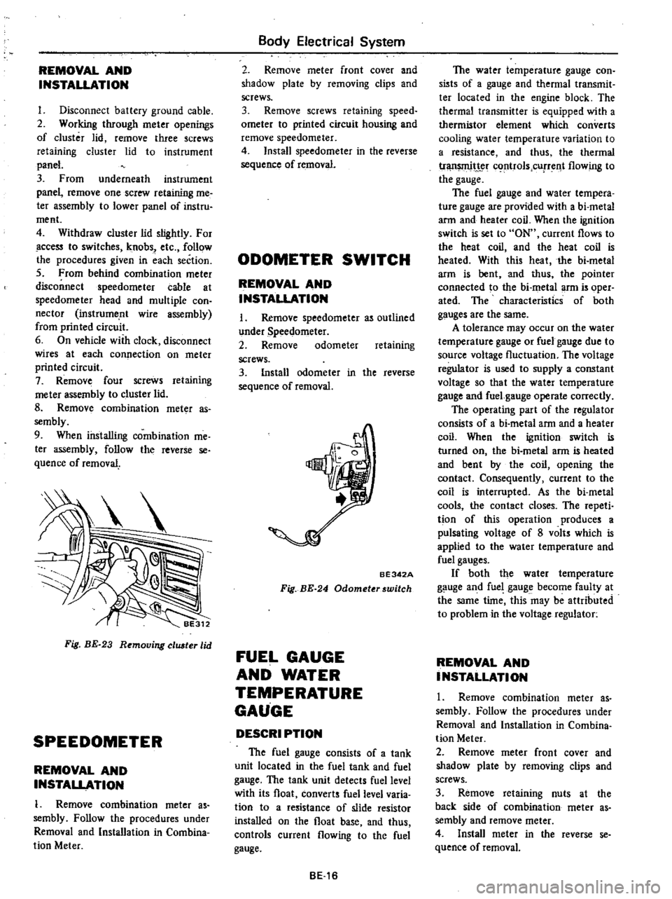
REMOVAL
AND
INSTALLATION
I
Disconnect
battery
ground
cable
2
Working
through
meter
openings
of
cluster
lid
remove
three
screws
retaining
cluster
lid
to
instrument
panel
3
From
underneath
instrument
panel
remove
one
screw
retaining
me
ter
assembly
to
lower
panel
of
instru
ment
4
Withdraw
cluster
lid
slightly
For
ccess
to
switches
knobs
etc
follow
the
procedures
given
in
each
section
5
From
behind
combination
meter
disconnect
speedometer
cable
at
speedometer
head
and
multiple
con
nector
instrume
nt
wire
assembly
from
printed
circuit
6
On
vehicle
with
clock
disconnect
wires
at
each
connection
on
meter
printed
circuit
7
Remove
four
screws
retaining
me
ter
assembly
to
cluster
lid
8
Remov
combination
meter
as
sembly
9
When
installing
combination
me
ter
assembly
follow
the
reverse
se
quence
of
removal
Fig
BE
23
Removing
eluster
lid
SPEEDOMETER
REMOVAL
AND
INSTALLATION
1
Remove
combination
meter
as
sembly
Follow
the
procedures
under
Removal
and
Installation
in
Combina
tion
Meter
Body
Electrical
System
2
Remove
meter
front
cover
and
shadow
plate
by
removing
clips
and
screws
3
Remove
screws
retaining
speed
ometer
to
printed
circuit
housing
and
remove
speedometer
4
Install
speedometer
in
the
reverse
sequence
of
removal
ODOMETER
SWITCH
REMOVAL
AND
INSTALLATION
I
Remove
speedometer
as
outlined
under
Speedometer
2
Remove
odometer
retaining
screws
3
Install
odometer
in
the
reverse
sequence
of
removal
BE342A
Fig
BE
24
Odometerswitch
FUEL
GAUGE
AND
WATER
TEMPERATURE
GAUGE
DESCRI
PTION
The
fuel
gauge
consists
of
a
tank
unit
located
in
the
fuel
tank
and
fuel
gauge
The
tank
unit
detects
fuel
level
with
its
float
converts
fuel
level
varia
tion
to
a
resistance
of
slide
resistor
installed
on
the
float
base
and
thus
controls
current
flowing
to
the
fuel
gauge
BE16
The
water
temperature
gauge
con
sists
of
a
gauge
and
thermal
transmit
ter
located
in
the
engine
block
The
thermal
transmitter
is
equipped
with
a
thermistor
element
which
converts
cooling
water
temperature
variation
to
a
resistance
and
thus
the
thermal
tr
t
c
rtrols
cUfTent
flowing
to
the
gauge
The
fuel
gauge
and
water
tempera
ture
gauge
are
provided
with
a
bi
metal
arm
and
heater
coil
When
the
ignition
switch
is
set
to
ON
current
flows
to
the
heat
coil
and
the
heat
coil
is
heated
With
this
heat
the
bi
metal
arm
is
bent
and
thus
the
pointer
connected
to
the
bi
metal
arm
is
oper
ated
The
characteristics
of
both
gauges
are
the
same
A
tolerance
may
occur
on
the
water
temperature
gauge
or
fuel
gauge
due
to
source
voltage
fluctuation
The
voltage
regulator
is
used
to
supply
a
constant
voltage
so
that
the
water
temperature
gauge
and
fuel
gauge
operate
correctly
The
operating
part
of
the
regulator
consists
of
a
bi
metal
arm
and
a
heater
coil
When
the
ignition
switch
is
turned
on
the
bi
metal
arm
is
heated
and
bent
by
the
coil
opening
the
contact
Consequently
current
to
the
coil
is
interrupted
As
the
bi
metal
cools
the
contact
closes
The
repeti
tion
of
this
operation
produces
a
pulsating
voltage
of
8
volts
which
is
applied
to
the
water
temperature
and
fuel
gauges
If
both
the
water
temperature
gauge
and
fuel
gauge
become
faulty
at
the
same
time
this
may
be
attributed
to
problem
in
the
voltage
regulator
REMOVAL
AND
INSTALLATION
1
Remove
combination
meter
as
sembly
Follow
the
procedures
under
Removal
and
Installation
in
Combina
tion
Meter
2
Remove
meter
front
cover
and
shadow
plate
by
removing
clips
and
screws
3
Remove
retaining
nuts
at
the
back
side
of
combination
meter
as
sembly
and
remove
meter
4
Install
meter
in
the
reverse
se
quence
of
removal
Page 464 of 537
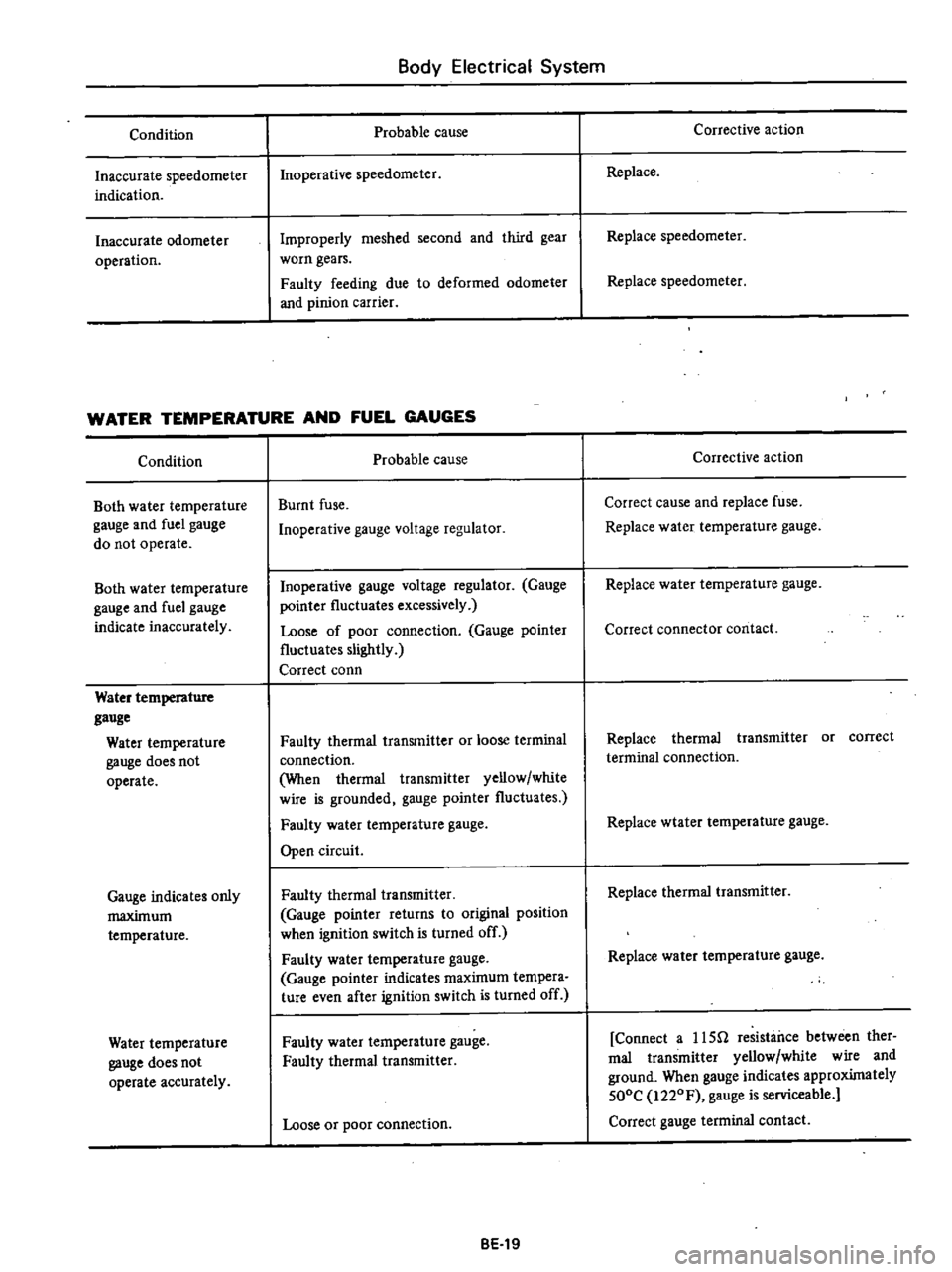
Condition
Inaccurate
speedometer
indication
Inaccurate
odometer
operation
Body
Electrical
System
Probable
cause
Inoperative
speedometer
Improperly
meshed
second
and
third
gear
worn
gears
Faulty
feeding
due
to
deformed
odometer
and
pinion
carrier
WATER
TEMPERATURE
AND
FUEL
GAUGES
Condition
Both
water
temperature
gauge
and
fuel
gauge
do
not
operate
Both
water
temperature
gauge
and
fuel
gauge
indicate
inaccurately
Water
temperature
gauge
Water
temperature
gauge
does
not
operate
Gauge
indicates
only
maximum
temperature
Water
temperature
gauge
does
not
operate
accurately
Probable
cause
Burnt
fuse
Inoperative
gauge
voltage
regulator
Inoperative
gauge
voltage
regulator
Gauge
pointer
fluctuates
excessively
Loose
of
poor
connection
Gauge
pointer
fluctuates
slightly
Correct
conn
Faulty
thermal
transmitter
or
loose
terminal
connection
When
thermal
transmitter
yellow
white
wire
is
grounded
gauge
pointer
fluctuates
Faulty
water
temperature
gauge
Open
circuit
Faulty
thermal
transmitter
Gauge
pointer
returns
to
original
position
when
ignition
switch
is
turned
off
Faulty
water
temperature
gauge
Gauge
pointer
indicates
maximum
tempera
ture
even
after
ignition
switch
is
turned
off
Faulty
water
temperature
gauge
Faulty
thermal
transmitter
Loose
or
poor
connection
BE
19
Corrective
action
Replace
Replace
speedometer
Replace
speedometer
Corrective
action
Correct
cause
and
replace
fuse
Replace
water
temperature
gauge
Replace
water
temperature
gauge
Correct
connector
contact
Replace
thermal
transmitter
or
correct
terminal
connection
Replace
wtater
temperature
gauge
Replace
thermal
transmitter
Replace
water
temperature
gauge
Connect
a
usn
resistance
between
ther
mal
transmitter
yellow
white
wire
and
ground
When
gauge
indicates
approximately
500C
i220F
gauge
is
serviceable
Correct
gauge
terminal
contact
Page 468 of 537
Body
Electrical
System
WINDSHIELD
WIPER
AND
WASHER
REMOVAL
AND
INSTALLATION
Wiper
linkage
I
Remove
wiper
blade
and
arm
assembly
from
pivot
2
Remove
cowl
top
grille
See
Sec
tion
BF
3
Remove
two
flange
nuts
retaining
pivot
wiper
linka
e
to
cowl
top
4
Remove
stop
ring
that
retains
connecting
rod
to
wiper
motor
arm
5
Remove
wiper
motor
linkage
as
sembly
6
Install
wiper
motor
linkage
in
the
reverse
sequence
of
removal
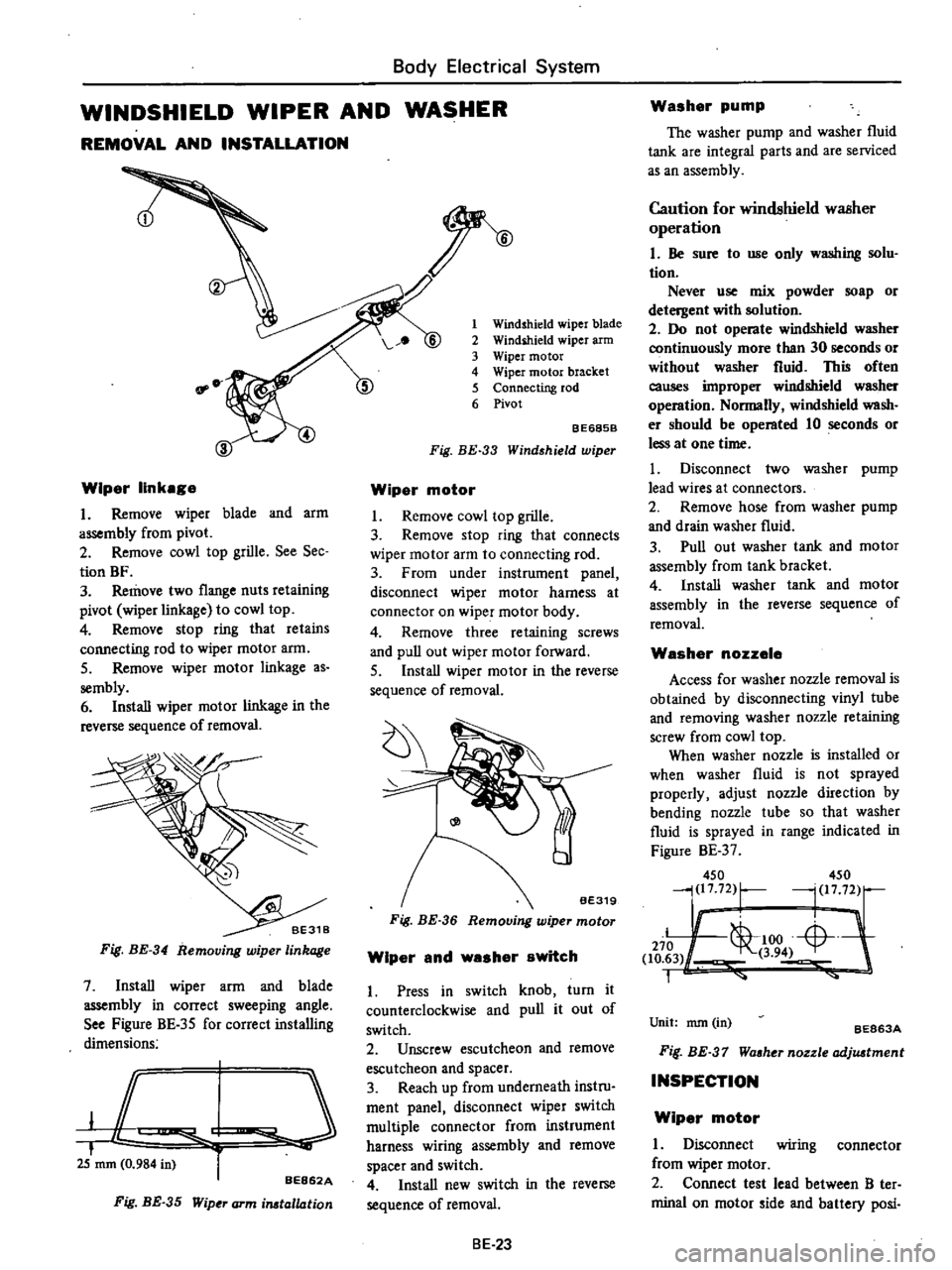
Fig
BE
34
Removing
wiper
linkage
7
Install
wiper
arm
and
blade
assembly
in
correct
sweeping
angle
See
Figure
BE
35
for
correct
installing
dimensions
JC
I
i
25
mm
0
984
in
r
BE862A
Fig
BE
35
Wip
J
arm
irutallation
1
Windshield
wiper
blade
2
Windihield
wiper
arm
3
Wiper
motor
4
Wiper
motor
bracket
5
Connecting
rod
6
Pivot
BE685B
Fig
BE
33
Wind
hield
wiper
Wiper
motor
I
Remove
cowl
top
grille
3
Remove
stop
ring
that
connects
wiper
motor
arm
to
connecting
rod
3
From
under
instrument
panel
disconnect
wiper
motor
harness
at
connector
on
wiper
motor
body
4
Remove
three
retaining
screws
and
pull
out
wiper
motor
forward
5
Install
wiper
motor
in
the
reverse
sequence
of
removal
Fig
BE
36
Wiper
and
washer
switch
1
Press
in
switch
knob
turn
it
counterclockwise
and
pull
it
out
of
switch
2
Unscrew
escutcheon
and
remove
escutcheon
and
spacer
3
Reach
up
from
underneath
instru
ment
panel
disconnect
wiper
switch
multiple
connector
from
instrument
harness
wiring
assembly
and
remove
spacer
and
switch
4
Install
new
switch
in
the
reverse
sequence
of
removal
BE
23
Washer
pump
The
washer
pump
and
washer
fluid
tank
are
integral
parts
and
are
serviced
as
an
assembly
Caution
for
windshield
waBher
operation
I
Be
sure
to
use
only
washing
solu
tion
Never
use
mix
powder
soap
or
detergent
with
solution
2
Do
not
operate
windshield
washer
continuously
more
than
30
seconds
or
without
washer
fluid
This
often
causes
improper
windshield
washer
operation
Normally
windshield
wash
er
should
be
operated
10
seconds
or
less
at
one
time
I
Disconnect
two
washer
pump
lead
wires
at
connectors
2
Remove
hose
from
washer
pump
and
drain
washer
fluid
3
Pull
out
washer
tank
and
motor
assembly
from
tank
bracket
4
Install
washer
tank
and
motor
assembly
in
the
reverse
sequence
of
removal
Washer
nozzele
Access
for
washer
nozzle
removal
is
obtained
by
disconnecting
vinyl
tube
and
removing
washer
nozzle
retaining
screw
from
cowl
top
When
washer
nozzle
is
installed
or
when
washer
fluid
is
not
sprayed
properly
adjust
nozzle
direction
by
bending
nozzle
tube
so
that
washer
fluid
is
sprayed
in
range
indicated
in
Figure
BE
37
450
450
j217
72
r
l
1772
Ii
L
1
00
Li
L
J
270
1
to
63
3
94
1
Unit
nun
in
BE863A
Fif
BE
37
Waaher
nozzle
adjuatment
INSPECTION
Wiper
motor
I
Disconnect
wiring
connector
from
wiper
motor
2
Connect
test
lead
between
B
ter
minal
on
motor
ide
and
battery
posi
Page 476 of 537
SEAT
BELT
WARNING
SYSTEM
DESCRIPTION
Except
Canada
When
the
ignition
switch
is
turned
to
the
ON
position
the
warning
lamp
comes
on
and
remains
on
for
4
to
8
seconds
The
warning
buzzer
sounds
for
4
to
8
seconds
intermittent
ly
if
the
driver
s
seat
belt
is
not
fastened
properly
The
seat
belt
warning
system
con
sists
of
a
driver
s
belt
switch
a
warning
buzzer
a
warning
lamp
a
timer
unit
and
an
ignition
switch
For
Canada
When
the
ignition
switch
is
turned
Body
Electrical
System
to
the
ON
position
the
warning
lamp
comes
on
and
the
warning
buz
zer
sounds
if
the
driver
s
seat
belt
is
not
fastened
properly
The
seat
belt
warning
system
con
sists
of
a
driver
s
belt
switch
a
warning
buzzer
a
warning
lamp
and
an
igni
tion
switch
REMOVAL
AND
INSTALLATION
Ignition
switch
Refer
to
page
BE
22
for
Removal
and
Installation
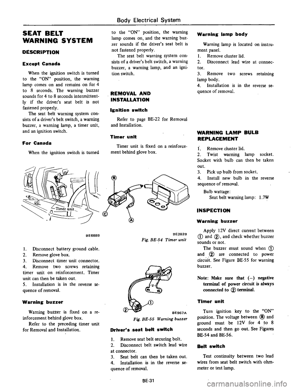
Timer
unit
Timer
unit
is
fIXed
on
a
reinforce
ment
behind
glove
box
BE688B
I
Disconnect
battery
ground
cable
2
Remove
glove
box
3
Disconnect
timer
unit
connector
4
Remove
two
screws
retaining
timer
unit
on
reinforcement
Timer
unit
can
then
be
taken
out
S
Installation
is
in
the
reverse
se
quence
of
removal
Warning
buzzer
Warning
buzzer
is
fIxed
on
a
re
inforcement
behind
glove
box
Refer
to
the
preceding
timer
unit
for
Removal
and
Installation
BE282B
Fig
BE
54
Timer
unit
BE967A
Fig
BE
55
Warning
buzzer
Driver
s
seat
belt
switch
I
Remove
seat
belt
ecuring
bolt
2
Disconnect
belt
switch
lead
wire
at
connector
3
Seat
belt
can
then
be
taken
out
4
Installation
is
in
the
reverse
se
quence
ofremoval
BE
31
Warning
lamp
body
Warning
lamp
is
located
on
instru
ment
panel
I
Remove
cluster
lid
2
Disconnect
lead
wire
at
connee
tor
3
Remove
two
screws
retaining
lamp
body
4
Installation
is
in
the
reverse
se
quence
of
removal
WARNING
LAMP
BULB
REPLACEMENT
I
Remove
cluster
lid
2
Twist
warning
lamp
socket
Socket
with
bulb
can
then
be
taken
out
3
Pick
up
bulb
from
socket
4
Install
new
bulb
in
the
reverse
sequence
of
removal
Bulb
wattage
Seat
belt
warning
lamp
I
7W
INSPECTION
Warning
buzzer
Apply
12V
direct
current
between
CD
and
@
and
check
whether
buzzer
sounds
or
not
The
buzzer
must
sound
when
CD
and
@
are
connected
to
power
circuit
See
Figure
BE
55
for
warning
buzzer
Note
Make
sure
that
negative
terminal
of
power
circuit
is
always
connected
to
@
terminal
Timer
unit
Turn
ignition
key
to
the
ON
position
The
voltage
between
@
and
ground
must
be
12V
for
4
to
8
seconds
and
then
go
out
See
Figures
BE
54
and
BE
56
Belt
switch
Test
continuity
between
two
lead
wires
from
seat
belt
switch
with
ohm
meter
or
test
lamp
Page 480 of 537
Body
Electrical
System
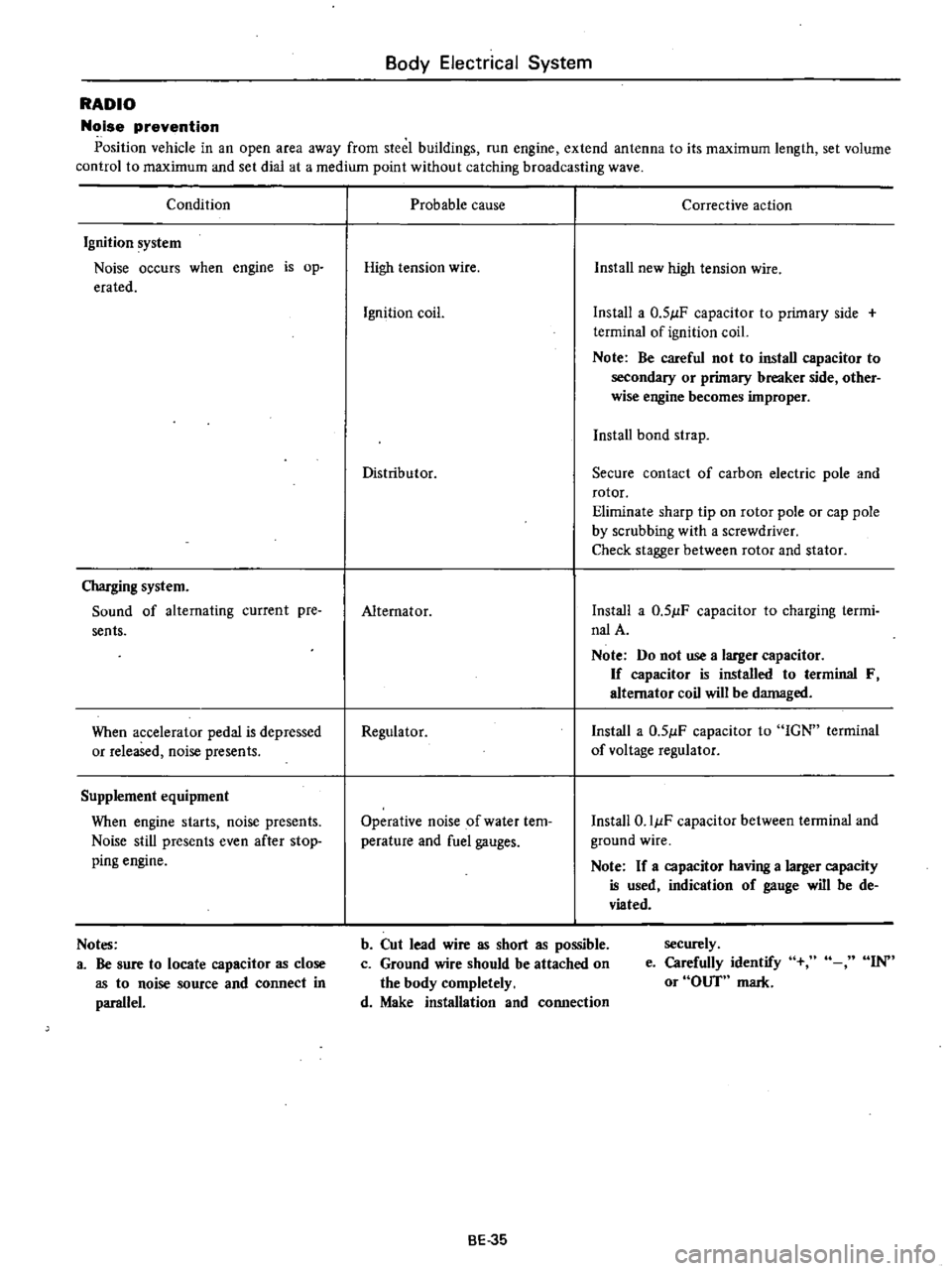
RADIO
Noise
prevention
Position
vehicle
in
an
open
area
away
from
steel
buildings
run
engine
extend
antenna
to
its
maximum
length
set
volume
control
to
maximum
and
set
dial
at
a
medium
point
without
catching
broadcasting
wave
Condition
Ignition
system
Noise
occurs
when
engine
is
op
erated
Charging
system
Sound
of
alternating
current
pre
sents
When
accelerator
pedal
is
depressed
or
released
noise
presents
Supplement
equipment
When
engine
starts
noise
presents
Noise
still
presents
even
after
stop
ping
engine
Notes
a
Be
sure
to
locate
capacitor
as
close
as
to
noise
source
and
connect
in
parallel
Probable
cause
Corrective
action
High
tension
wire
Install
new
high
tension
wire
Ignition
coil
Install
a
0
51lF
capacitor
to
primary
side
terminal
of
ignition
coil
Note
Be
careful
not
to
install
capacitor
to
secondary
or
primary
breaker
side
other
wise
engine
becomes
improper
Install
bond
strap
Distributor
Secure
contact
of
carbon
electric
pole
and
rotor
Eliminate
sharp
tip
on
rotor
pole
or
cap
pole
by
scrubbing
with
a
screwdriver
Check
stagger
between
rotor
and
stator
Alternator
Install
a
0
51lF
capacitor
to
charging
termi
nalA
Note
Do
not
use
a
larger
capacitor
If
capacitor
is
installed
to
terminal
F
alternator
coil
will
be
damaged
Regulator
Install
a
0
51lF
capacitor
to
IGN
terminal
of
voltage
regulator
Operative
noise
of
water
tem
perature
and
fuel
gauges
Install
O
IIlF
capacitor
between
terminal
and
ground
wire
Note
If
a
capacitor
having
a
larger
capacity
is
used
indication
of
gauge
will
be
de
viated
b
Cut
lead
wire
as
short
as
possible
c
Ground
wire
should
be
attached
on
the
body
completely
d
Make
installation
and
connection
securely
e
Carefully
identify
or
OUT
mark
IN
BE
35