check DATSUN PICK-UP 1977 Service Manual
[x] Cancel search | Manufacturer: DATSUN, Model Year: 1977, Model line: PICK-UP, Model: DATSUN PICK-UP 1977Pages: 537, PDF Size: 35.48 MB
Page 283 of 537

Automatic
Transmission
N
ranee
Neutral
I
a
a
8
nd
011
Coolei
VK
Th
o
Vtlv
J
@
Vtlv
I
I
D
ln
Ol
v
Lubrlc
tlon
11
I
OIIt
Lubrlut
O
lfIC
Check
Vtlv
D
lnV
I
T
uott
O
in
v
8Jl
12
ht
2nd
Shift
y
tve
5
CD
Rl9UlttO
Vtlv
Nott
M
rked
X
r
D
in
liia
1
or
IOo
nOf
fNd
IH
oov
no
p
c
z
Torqu
con
er
pr
Throttl
p
s
cond
y
a
Ol
V
o
V
tve
Fig
AT
29
AT
19
Oil
pressure
circuit
diagram
N
range
Neutral
Page 289 of 537

Automatic
Transmission
0
range
Top
gear
Low
A
lI
eke
B
e
I
mf
D
J
J
V
va
I
011
COO
VK
Thro
V
o
Ot
al
oi
v
L
R
Lubfkatlon
y
Front
Lubric
1
n
Oriliu
Check
1
1
O
nV
Th
onla
O
eln
Vah
2
P
M
lflM
V
I
5
22
x
i2J
3
1n
2nd
Shift
v
1Ye
5
Manue
Val
PRND2
j
Pr
R
I
Of
1
1
5
Nota
Marked
r
Dr
ln
rs
ond
y
l
y
G
nor
Val
Goy
rnor
Val
1
1
IOo
no
feold
P
Oo
no
p
Torq
c
on
n
p
Th
onl
pr
Fig
A
T
38
Oil
pressure
circuit
diagram
uD
J
range
Top
gear
AT
25
Page 291 of 537

Automatic
Transmission
I
M
nual
f4fL
J
0
I
1
r
PR
0
range
kickdown
Shift
valves
In
2nd
gear
position
To
queeO
t
Front
Clutch
Low
a
A
8
8
e
e
a
o
14
0
Oil
COO
R
L
ubrication
n
0
Drain
1
4
j
v
I
Front
Lub
icet
p
n
o
I
Thron
p
ain
V
I
j
R
gu
ato
V
I
Not
Ma
ked
X
r
p
n
Li
pr
IGo
no
f
d
p
l
Governor
p
c
Torque
CO
I
1
p
ThrOWepr
VK
Th
o
V
lv
7
1
iftV
8
Throttle
BKk
up
V
hl
ID
So
e
COw
P
Ifk
Check
V
I
1
24
5
Mod
Yo
I
@2nCl
3rdSl
lilr
V
12
3
ht
2nd
Shih
V
5
L
I
X
S
COnd
Primary
G
rw
Va
Gov
nor
Valve
AT
27
Fig
AT
39
Oil
pressure
circuit
diagram
D
ronge
kickdown
shift
values
in
2nd
gear
position
Page 293 of 537

Automatic
Transmission
2
range
2nd
gear
Torqu
Con
Fron
Clutch
l
ow
A
B
ke
Br
I
12
011
Cool
i
IL
12
ID
v
Th
ot
Valve
7
T
onl
Beck
up
V
ID
So
0
Id
1ft
v
Front
Lubric
t
Orltic
Check
Va
Or
lnVal
e
Throttle
Dr
in
V
l
P
Modif
Va
15
BJl
@
2nct
3rd
Tim
If
Ve
12
3
1
2nd
Stolt
21
Se
onc
l
Lock
Va
3
I
PR
02
1
s
I
Jl
J
I
r
A
ul
Gr
v
2
w
Valve
Note
Merltedl
D
a
n
I
G
v
Line
p
IOo
nOf
f
d
pr
G
no
p
r
c
o
Torque
con
pr
Thron
p
re
ond
a
nor
v
Fig
A
T
42
Oil
pressure
circuit
diagram
2
range
2nd
gear
AT
29
Page 298 of 537
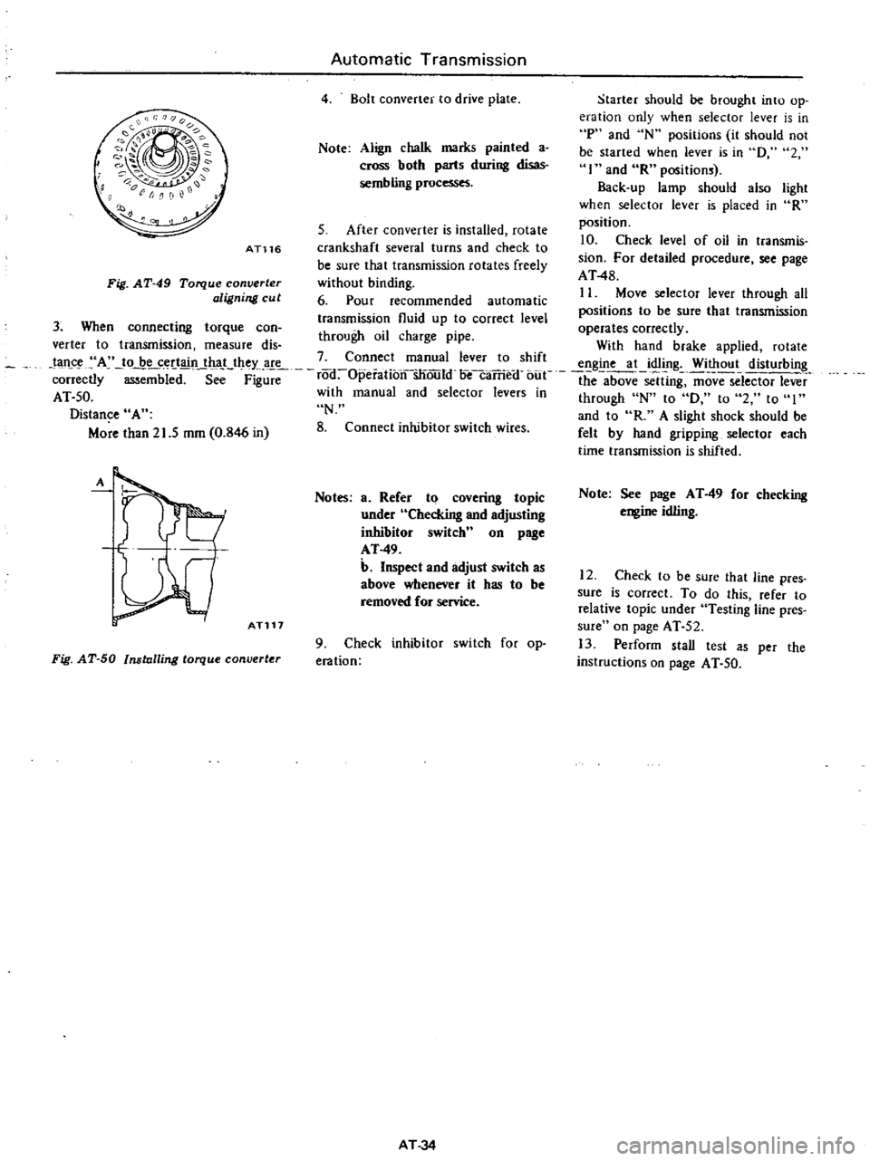
Starter
should
be
brought
into
op
eration
only
when
selector
lever
is
in
P
and
N
positions
it
should
not
be
started
when
lever
is
in
D
2
I
and
R
positions
Back
up
lamp
should
also
light
when
selector
lever
is
placed
in
R
position
S
After
converter
is
installed
rotate
10
Check
level
of
oil
in
transmis
crankshaft
several
turns
and
check
to
be
sure
that
transmission
rotates
freely
sion
For
detailed
procedure
see
page
AT48
without
binding
6
Pour
recommended
automatic
II
Move
selector
lever
through
aU
positions
to
be
sure
that
transmission
transmission
fluid
up
to
correct
level
operates
correctly
through
oil
charge
pipe
verter
to
transmission
measure
dis
With
hand
brake
applied
rotate
tan
A
to
be
certain
that
they
are
7
Connect
manual
lever
to
shift
engine
at
idling
Without
disturbing
correctly
mbi
d
S
F
rod
Opeiationsliould
oecaTrie
f
bue
the
above
sclUng
ffiovTSelector
lever
AT
50
with
manual
and
selector
levers
in
through
N
to
D
to
2
to
I
Distance
A
N
and
to
R
A
slight
shock
should
be
More
than
21
5
mm
0
846
in
8
Connect
inhibitor
switch
wires
felt
by
hand
gripping
selector
each
time
transmission
is
shifted
Automatic
Transmission
4
Bolt
converter
to
drive
plate
Note
Align
chalk
marks
painted
a
cross
both
parts
during
disas
sembling
processes
AT116
Fig
AT
49
Torque
converter
aligning
cu
t
3
When
connecting
torque
can
A
ATl17
Notes
a
Refer
to
covering
topic
under
Checking
and
adjusting
inhibitor
switch
n
on
page
AT
49
b
Inspect
and
adjust
switch
as
above
whenever
it
has
to
be
removed
for
service
Fig
AT
50
Installing
torque
converter
9
Check
inhibitor
switch
for
op
eration
AT
34
Note
See
page
AT
49
for
checking
engine
idling
12
Check
to
be
sure
that
line
pres
sure
is
correct
To
do
this
refer
to
relative
topic
under
Testing
line
pres
sure
on
page
AT
52
13
Perform
stall
test
as
per
the
instructions
on
page
AT
50
Page 299 of 537

Automatic
Transmission
TRANSMISSION
CONTROL
LINKAGE
4
120N
L
B
j
p
r
4
1
Control
lever
knob
2
Pusher
3
Control
lever
assembly
4
Selector
range
lever
5
Control
lever
bracket
6
Selector
rod
REMOVAL
AND
INSTALLATION
1
Disconnect
control
knob
from
control
lever
by
removing
two
2
screws
2
Remove
console
box
3
Remove
selector
rod
selector
range
lever
and
control
lever
assembly
with
bracket
To
install
reverse
the
order
of
removal
ADJUSTMENT
The
adjustment
of
linkage
is
as
Tightening
torque
1
of
nuts
and
screw
kg
m
ft
lb
G
A
T273
@
T
0
07
to
0
13
0
5
to
0
9
@
T
1
6
to
2
2
12
to
16
T
3
to
4
22
to
29
@
T
0
35
to
0
45
2
5
to
3
3
C8i
T
0
8
to
1
1
6
to
8
important
as
Inspection
of
oil
level
for
the
automatic
transmission
Therefore
great
care
should
be
exercised
because
faulty
adjustment
will
result
in
the
breakdown
of
the
transmission
1
Prior
to
installing
control
knob
set
the
dimension
A
to
II
to
12
mm
0
43
to
0
47
in
2
Install
control
knob
on
lever
At
the
same
time
check
the
dimension
B
and
adjust
it
to
0
1
to
1
1
mm
0
004
to
0
043
in
by
turning
pusher
@
See
Figure
AT
51
AT
35
Fig
AT
51
Controlli
f
kage
sy
tem
3
Loosen
adjust
nuts
@
Set
control
lever
@
and
selector
lever
@
at
N
position
moreover
J
set
the
clearance
C
to
I
mm
0
039
in
by
turning
in
or
out
adjusting
nuts
at
trunnion
with
connects
selector
rod
@
After
adjusting
make
sure
that
control
lever
can
be
set
in
any
position
correctly
and
that
selector
lever
oper
ates
properly
without
any
binding
If
levers
do
not
operate
satisfactori
ly
readjust
or
replace
parts
as
neces
sary
Page 300 of 537
Automatic
Transmission
MAJOR
REPAIR
OPERATION
SERVICE
NOTICE
FOR
DISASSEMBLY
AND
ASSEMBLY
TORQUE
CONVERTER
INSPECTION
TRANSMISSION
DISASSEMBL
Y
INSPECTION
ASSEMBL
Y
SERVICE
NOTICE
FOR
DISASSEMBLY
AND
ASSEMBLY
I
It
is
advisable
that
repair
opera
tions
be
carried
out
in
a
dust
proof
room
2
Due
to
the
differences
of
the
engine
capacities
the
specifications
of
component
parts
for
each
model
s
transmission
may
be
different
They
do
however
have
common
adjust
ment
and
repair
procedures
as
well
as
cleaning
and
inspection
procedures
outlined
hereinafter
3
During
repair
operations
refer
to
Service
Data
and
Specifications
see
tion
for
the
correct
parts
for
each
model
4
Before
removing
any
of
subas
semblies
thoroughly
clean
the
outside
of
the
transmission
to
prevent
dirt
from
entering
the
mechanical
parts
5
Do
not
use
a
waste
rag
Use
a
nylon
or
paper
cloth
6
After
disassembling
wash
all
dis
assembled
parts
and
examine
them
to
see
if
there
are
any
worn
damaged
or
defective
parts
and
how
they
are
affected
Refer
to
Service
Data
for
the
extent
of
damage
that
justifies
replacement
7
As
a
rule
packings
seals
and
similar
parts
once
disassembled
should
be
replaced
with
new
ones
TORQUE
CONVERTER
The
torque
converter
is
a
welded
construction
and
can
not
be
disas
sembled
CONTENTS
AT
36
AT
36
AT
36
AT
36
AT
36
AT
38
AT
38
COMPONENT
PARTS
FRONT
CLUTCH
REAR
CLUTCH
LOW
REVERSE
BRAKE
SERVO
PISTON
GOVERNOR
OIL
PUMP
PLANETARY
CARRIER
CONTROL
VALVE
AT
40
AT
40
AT
41
AT
42
AT
42
AT
43
AT
43
AT
44
AT
44
INSPECTION
2
Remove
bolts
securing
converter
1
Check
torque
convertf
for
any
housing
to
transmission
case
Remove
sign
of
damage
bending
oil
leak
or
torque
converter
deformation
If
necessary
replace
3
Remove
speedometer
pinion
2
Remove
rust
from
pilots
and
sleeve
bolt
Withdraw
pinion
bosses
completely
4
Remove
downshift
solenoid
and
If
torque
converter
oil
is
fouled
or
vacuum
diaphragm
Do
not
leave
dia
contaminated
due
to
burnt
clutch
phragm
rod
at
this
stage
of
disas
flush
the
torque
converter
as
follows
sembly
Rod
is
assembled
in
top
of
vacuum
diaphragm
See
Figure
I
Drain
oil
in
torque
converter
AT
53
2
Pour
non
lead
gasoline
or
kero
sene
into
torque
converter
approxi
mately
0
5
liter
I
U
S
pt
U
Imp
pt
3
Blow
air
into
torque
converter
and
flush
and
drain
out
gasoline
4
Fill
torque
converter
with
torque
converter
oil
approximately
0
5
liter
I
V
S
pt
U
Imp
pt
5
Again
blow
air
into
torque
con
verter
and
drain
torque
converter
oil
TRANSMISSION
DISASSEMBLY
I
Drain
oil
from
the
end
of
rear
extension
Mount
transmission
on
Transmission
Case
Stand
ST07870000
or
ST07860000
Remove
oil
pan
See
Figure
AT
52
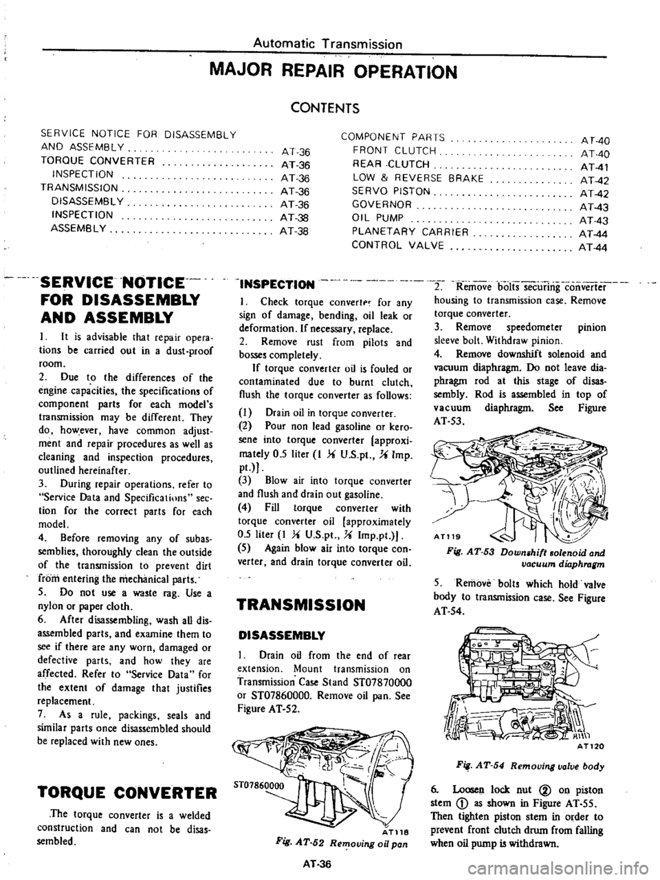
AT118
Fig
AT
52
Removing
oil
pan
AT
36
Fig
AT
53
Down
hilt
olenoid
and
vacuum
dilJphragm
5
Remove
bolts
which
hold
valve
body
to
transmission
case
See
Figure
AT
54
Fig
AT
54
Removing
valve
body
6
Loosen
lock
nut
@
on
piston
stem
D
as
shown
in
Figure
AT
55
Then
tighten
piston
stem
in
order
to
prevent
front
clutch
drum
from
falling
when
oil
pump
is
withdrawn
Page 302 of 537

I
i
0
t
V
iL
1
0
ST25570001
j
w
1
h
AT130
Fig
AT
64
Removing
hex
head
slotted
bolt
19
Blowout
low
and
reverse
brake
piston
by
directing
a
jet
of
air
into
holeJn
cylinder
See
F
igure
AT
65
Fig
AT
65
Removing
piston
20
Remove
band
servo
loosening
attaching
bolts
Note
If
difficulty
is
encountered
in
removing
retainer
direct
a
jet
of
air
toward
release
side
as
shown
in
Figure
AT
66
II
AP
fW
l
1
A
T132
Fig
AT
fiB
Removing
bond
servo
21
Pry
snap
rings
CD
from
both
ends
of
parking
brake
lever
@
and
remove
the
lever
Back
off
manual
shaft
lock
nut
ID
and
remove
manual
plale
@
and
parking
rod
CID
See
Figure
AT
67
Automatic
Transmission
Up
@
J1i
ll
J
t
i
p
lli
l
1
I
l
P
l
1
Ii
@
j
Y
L
l
rr
i
J
ry
j
AT133
Fig
AT
67
Removing
manual
plate
22
Remove
inhibitor
switch
and
manual
shaft
by
loosening
two
secur
ing
bolts
INSPECTION
Torque
c
onverter
housing
transmission
c
ase
and
rear
extension
I
Check
for
damage
or
cracking
if
necessary
replace
2
Check
for
dents
or
score
marks
on
mating
surfaces
Repair
as
nee
essary
3
If
rear
extension
bushing
is
worn
or
cracked
replace
it
as
an
assembly
of
bushing
and
rear
extension
housing
Gaskets
and
O
ring
1
Always
use
new
gaskets
when
the
units
are
to
be
disassembled
2
Check
O
rings
for
burrs
or
crack
ing
If
necessary
replace
with
new
rings
011
distributor
I
Check
for
signs
of
wear
on
seal
ring
and
ring
groove
replacing
with
new
ones
if
found
worn
beyond
use
Check
that
clearance
between
seal
ring
and
ring
groove
is
correct
If
out
of
specification
replace
whichever
is
worn
beyond
limits
Correct
clearance
is
from
0
04
to
0
16
mm
0
0016
to
0
0063
in
See
Figure
AT
68
AT
J8
j
Clearance
1
61
Seal
dng
0
j
J
I
I
AT134
ig
A
r
68
Me
q
sur
ingseal
r
ing
to
ring
groove
clearance
ASSEMBLY
Assembly
is
in
reverse
order
of
disassembly
However
observe
the
fol
lowing
assembly
notes
After
installing
piston
of
low
and
reverse
orake
assemble
thrust
spring
ring
return
spring
thrust
washer
and
one
way
clutch
inner
race
Torque
hex
head
slotted
bolt
to
L3to
1
8
kg
m
9
to
13
ft
ib
using
Hex
head
Ex
tension
ST2SS7000
ST2SS70000
Torque
Wrench
GG93010000
and
Socket
Extension
ST2S490000
ST2SS
12001
See
Figure
AT
69
ST2557000t
ST25490000
I
GG930JOOOO
A
T135
Fig
AT
69
Installing
ont
woy
clutch
inner
race
2
After
low
and
reverse
brake
has
been
assembled
measure
the
clearance
between
snap
ring
CD
and
retaining
plate
@
Select
proper
thickness
of
retaining
plate
to
give
correct
ring
to
plate
clearance
See
Figure
AT
70
Low
and
reverse
brake
clearance
0
80
to
1
05
rom
0
0315
to
0
0413
in
Page 303 of 537

Fig
AT
70
Measuring
ring
to
plate
clearance
Available
retaining
plate
Thickness
mm
in
1l
8
0
465
12
0
0472
12
2
0480
124
0488
12
6
0496
12
8
0
504
For
inspection
procedure
for
low
and
reverse
brake
see
page
AT
42
for
Assembly
3
Install
one
way
clutch
so
that
the
arrow
mark
is
toward
front
of
vehicle
It
should
be
free
to
rotate
only
in
clockwise
direction
See
Figure
AT
71
mITIJ
o
oml
AT137
Fig
AT
71
One
way
clutch
4
After
installing
rear
extension
torque
attaching
bolts
to
2
0
to
2
5
kg
m
14
to
18
ft
lb
Place
manual
lever
in
P
range
and
check
to
be
sure
that
rear
output
shaft
is
securely
blocked
5
Tighten
servo
retainer
temporari
ly
at
this
stage
of
assembly
6
Place
rear
clutch
assembly
with
needle
bearing
on
front
assembly
Automatic
Transmission
7
Install
rear
clutch
hub
and
front
planetary
carrier
as
shown
in
Figure
AT
72
AT142
Fig
AT
72
Installing
planetary
carrier
8
Assemble
connecting
shell
and
other
parts
up
to
front
Clutch
in
reverse
order
of
disassembly
AT143
Fig
AT
73
Installing
connecting
shell
9
Adjust
total
end
play
and
front
end
playas
follows
Front
end
play
L
r
L
CD
I
r
L
11
I
J
Total
end
play
@
Front
clutch
thrust
washer
2
Oil
pump
cover
3
Front
clutch
4
Rear
clutch
AT138
5
Trammission
case
6
Oil
pump
gasket
7
Oil
pump
cover
bearing
race
Fig
AT
74
End
play
1
Measure
the
distance
A
and
C
by
vernier
calipers
as
shown
in
Figure
AT
75
AT
39
i
Rear
c
clutch
N
edle
bearing
Bearing
race
I
Fig
AT
75
AT139
Measuring
the
distance
A
and
C
2
Measure
the
distance
B
and
D
of
oil
pump
cover
as
shown
in
Figure
AT
76
I
L
I
Oiipi
mp
AT140
Fig
AT
76
Measuring
the
distance
B
and
D
Adjustment
of
total
end
play
Select
oil
pump
cover
bearing
race
by
calculating
the
following
formula
TT
A
B
W
where
T
T
Required
thickness
of
oil
pump
cover
bearing
race
mm
in
A
Measured
distance
A
mm
in
B
Measured
distance
B
mm
in
W
Thickness
of
bearing
race
temporarily
inserted
mm
in
Available
oil
pump
cover
bearing
race
Thickness
mm
in
1
2
0
047
I
4
0
055
1
6
0
063
1
8
0
071
2
0
0
079
2
2
0
087
Specified
total
end
play
0
25100
50
mm
0
0098
to
0
0197
in
Page 304 of 537
Adjustment
of
front
end
play
Sele
t
front
dutch
thrust
washer
by
calculating
the
following
formula
T
F
C
D
0
2
mm
where
T
F
Required
thickness
of
front
clutch
thrust
washer
mm
in
C
Measured
distance
C
mm
in
D
Measured
distance
D
mm
in
Available
front
clutch
thrust
washer
Thickness
mm
in
1
5
0
059
I
7
0
067
1
9
0
075
2
1
0
083
2
3
0
091
2
5
0
098
27
0
106
Specified
front
end
play
0
5
to
0
8
mm
0
020
to
0
031
in
Notes
a
Correct
thickness
of
bearing
race
and
thrust
washer
is
always
the
one
which
is
nearest
the
calculated
one
b
Installed
thickness
of
oil
pump
gas
ket
is
0
4
mm
0
016
in
10
Check
to
be
sure
that
brake
servo
piston
moves
freely
For
detailed
ptocedure
refer
to
page
AT
42
for
Servo
Piston
Use
care
to
prevent
piston
from
coming
out
of
place
dUI
ing
testing
since
servo
retainer
is
not
tightened
at
this
point
of
assembly
II
Make
sure
that
brake
band
strut
is
correctly
installcd
Torque
piston
stem
to
1
2
to
1
5
kg
m
9
to
11
f1
lb
Back
off
two
full
lurns
and
secure
with
lock
nut
Lock
nut
tight
ening
torque
is
1
5
to
4
0
kg
m
II
to
9
f1
lb
Automatic
Transmission
12
After
inhibitor
switch
is
in
stalled
check
to
be
sure
that
it
op
erates
properly
in
each
range
For
detailed
procedure
refer
to
page
AT
49
for
Checl
ing
and
Adjusting
Inhibi
tor
Switch
13
Check
the
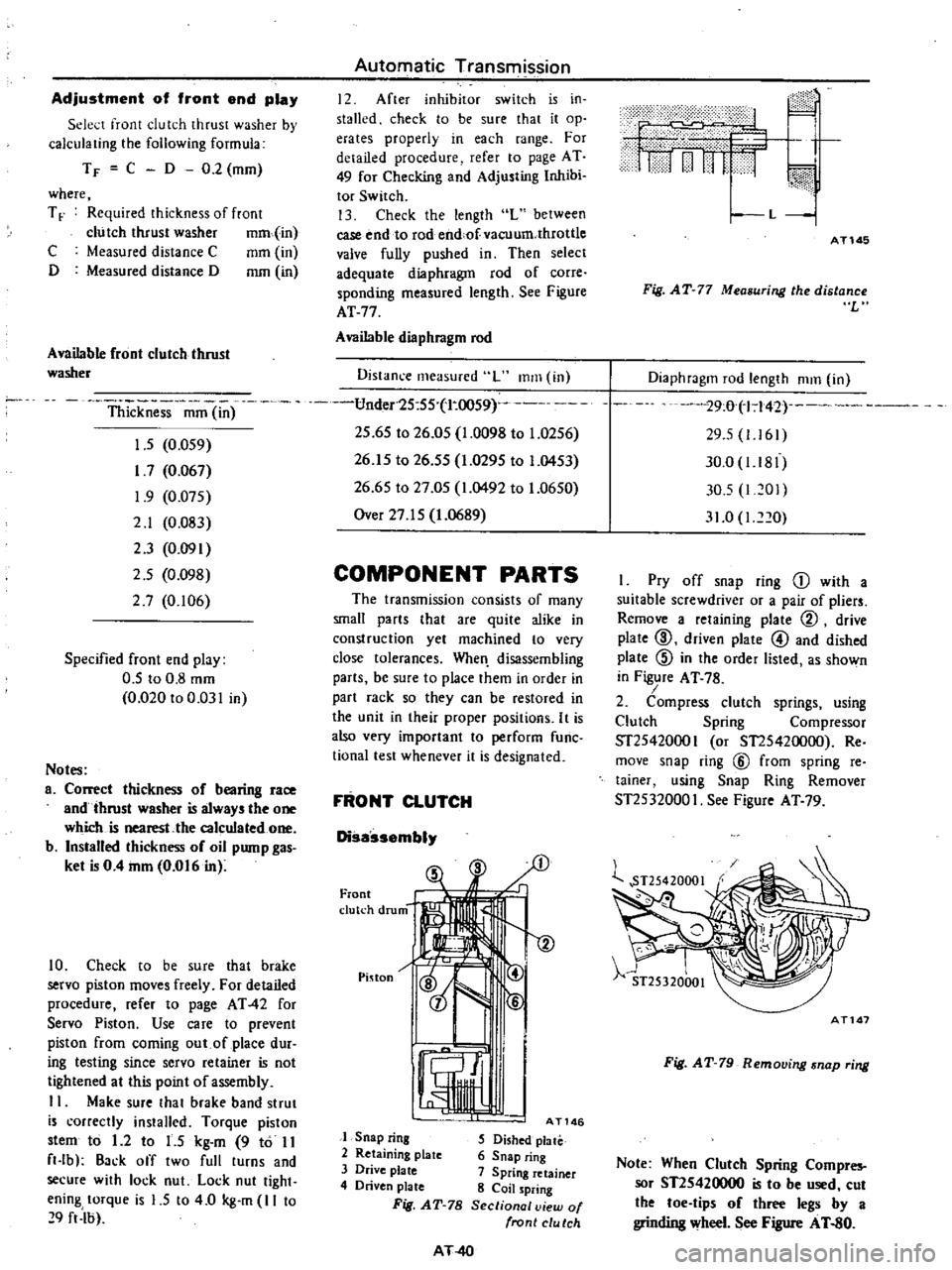
length
L
between
case
end
to
rod
end
ofvacuum
throllle
valve
fully
pushed
in
Then
select
adequate
diaphragm
rod
of
corre
sponding
measured
length
See
Figure
AT
77
Available
diaphragm
rod
Distanl
e
measured
L
ITIm
in
Under25
55
l
OO59
25
65
to
26
05
1
0098
to
1
0256
26
15
to
26
55
1
0295
to
1
0453
26
65
to
27
05
1
0492
to
1
0650
Over
27
15
1
0689
COMPONENT
PARTS
The
transmission
cons
sts
of
many
small
parts
that
are
quite
alike
in
construction
yet
machined
to
very
close
tolerances
When
disassembling
parts
be
sure
to
place
them
in
order
in
part
rack
so
they
can
be
restored
in
the
unit
in
their
proper
positions
It
is
also
very
important
to
perform
func
tianal
test
whenever
it
is
designated
FRONT
CLUTCH
Disassembly
Front
clutch
drum
I
Pinon
lcz
t
AT146
1
Snap
ring
2
Retaining
plate
3
Drive
plate
4
Driven
plate
Fit
AT
78
S
Dished
plate
6
Snap
ring
7
Spring
retainer
8
Coil
spring
Sectional
view
of
front
clu
tch
AT
40
i
i
n
H
I
I
ni
c
A
i
iif
L
1
AT145
Fig
AT
77
Measuring
the
distance
L
Diaphragm
rod
length
mm
in
29
00
142
u
29
5
1161
30
0
1
81
30
5
1201
31
0
I
O
I
Pry
off
snap
ring
D
with
a
suitable
screwdriver
or
a
pair
of
pliers
Remove
a
retaining
plate
@
drive
plate
CID
driven
plate
@
and
dished
plate
@
in
the
order
listed
as
shown
in
Figure
AT
78
I
2
Compress
clutch
springs
using
Clutch
Spring
Compressor
ST25420001
or
51
25420000
Re
move
snap
ring
@
from
spring
re
tainer
using
Snap
Ring
Remover
ST2532000
I
See
Figure
AT
79
AT147
Fig
AT
79
Removing
snap
ring
Note
When
Clutch
Spring
Compres
sor
ST25420000
is
to
be
used
cut
the
toe
tips
of
three
legs
by
a
grinding
wheel
See
Figure
AT
80