check DATSUN PICK-UP 1977 Service Manual
[x] Cancel search | Manufacturer: DATSUN, Model Year: 1977, Model line: PICK-UP, Model: DATSUN PICK-UP 1977Pages: 537, PDF Size: 35.48 MB
Page 361 of 537
WHEEL
ALIGNMENT
Correct
front
wheel
alignment
attains
proper
vehicle
handling
charac
teristics
and
the
least
steering
effort
with
a
minimum
amount
of
tire
wear
Before
adjusting
front
wheel
align
ment
make
sure
to
carry
out
a
pre
liminary
inspection
of
the
front
end
parts
for
the
following
conditions
1
Tire
pressure
and
balance
2
Wheel
bearings
and
nuts
3
Steering
gear
play
4
Steering
gear
housing
at
frame
S
Steering
linkage
and
connections
6
Shock
absorber
action
When
using
the
equipment
for
front
wheel
alignment
inspection
follow
the
inst
c
tions
furnished
with
the
equip
ment
Furthennore
the
inspection
should
be
made
with
the
vehicle
level
and
at
curb
weight
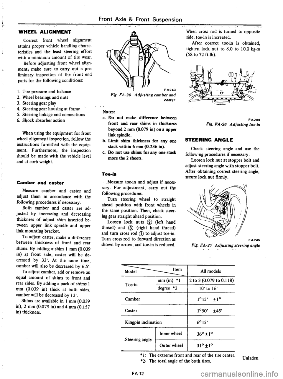
Camber
and
caster
Measure
camber
and
caster
and
adjust
them
in
accordance
with
the
following
procedures
if
necessary
Both
camber
and
caster
are
ad
justed
by
increasing
and
decreasing
thickness
of
adjust
shim
inserted
be
tween
upper
link
spindle
and
upper
link
mounting
bracket
To
adjust
caster
make
a
difference
between
thickness
of
front
and
rear
shims
By
adding
a
shim
I
mm
0
039
in
at
front
side
caster
will
be
de
creased
by
33
At
the
same
time
camber
will
also
be
decreased
by
6
S
To
adjust
camber
add
or
remove
an
equal
amount
of
shims
to
front
and
rear
sides
By
adding
a
pack
of
shims
I
mOl
0
039
in
thick
at
both
sides
camber
will
be
decreased
by
13
Shims
are
available
in
I
mm
0
039
in
2
mOl
0
079
in
and
4
mOl
0
157
in
thickness
Front
Axle
Front
Suspension
FA243
Fig
FA
25
Adjustingcamberand
cCJ
ter
Notes
a
Do
not
make
difference
between
front
and
rear
shims
in
thickness
beyond
2
mm
0
079
in
on
a
upper
link
spindle
b
Umit
shim
thickness
for
anyone
stack
within
6
nun
0
236
in
c
Do
not
use
shims
for
anyone
stack
more
the
2
sheets
Toe
in
Measure
toe
in
and
adjust
if
neces
sary
For
adjustment
carry
out
the
follOWIng
procedures
Turn
steering
wheel
to
straight
ahead
position
with
front
wheels
in
the
same
position
Then
check
steer
ing
gear
straight
ahead
position
Loosen
lock
nuts
@
left
hand
thread
and
ID
right
hand
thread
and
turn
cross
rod
CD
to
adjust
toe
in
Turn
cross
rod
to
forward
direction
as
shown
by
arrow
and
toe
in
is
reduced
When
cross
rod
is
turned
to
opposite
side
toe
in
is
increased
After
correct
toe
in
is
obtained
tighten
lock
nut
to
8
0
to
10
0
kg
m
S8
to
72
ft
Ib
r
J
r
CD
0
HI
r
I
e
f
FA244
Fig
FA
26
Adju6ting
toe
in
STEERING
ANGLE
Check
steering
angle
and
use
the
follow
ng
procedures
if
necessary
Loosen
lock
nut
at
stopper
bolt
and
adjust
steering
angle
with
stopper
bolt
Mter
obtaining
correct
steering
angle
secure
lock
nut
firmly
FA245
Fig
FA
27
Adjusting
steering
angle
Model
Item
All
models
mOl
in
1
2
to
3
0
079
to
0
118
Toe
in
degree
2
10
to
16
Camber
lOIS
Io
Caster
10SO
4S
I
60IS
Kingpin
inc
inal10n
I
Inner
wheel
360
10
Steering
angle
I
Outer
wheel
310
10
1
The
extreme
front
and
rear
of
the
tire
center
Unladen
2
The
total
angle
of
the
both
tires
FA
12
Page 364 of 537
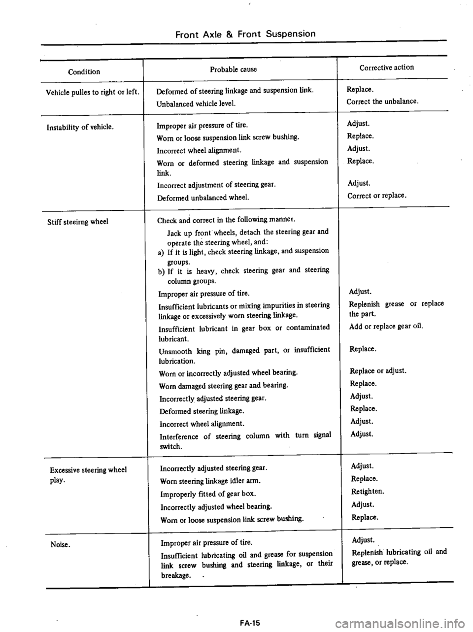
Condition
Vehicle
puBes
to
right
or
left
Instability
of
vehicle
Stiff
steeirng
wheel
Excessive
steering
wheel
play
Noise
Front
Axle
Front
Suspension
Probable
cause
Deformed
of
steering
linkage
and
suspension
link
Unbalanced
vehicle
level
Improper
air
pressure
of
tire
Worn
or
loose
suspension
link
screw
bushing
Incorrect
wheel
alignment
Worn
or
deformed
steering
linkage
and
suspension
link
Incorrect
adjustment
of
steering
gear
Deformed
unbalanced
wheel
Check
and
correct
in
the
following
manner
Jack
up
front
wheels
detach
the
steering
gear
and
operate
the
steering
wheel
and
a
If
it
is
light
check
steering
linkage
and
suspension
groups
b
If
it
is
heavy
check
steering
gear
and
steering
column
groups
Improper
air
pressure
of
tire
Insufficient
lubricants
or
mixing
impurities
in
steering
linkage
or
excessively
worn
steering
linkage
Insufficient
lubricant
in
gear
box
or
contaminated
lubricant
Unsmooth
king
pin
damaged
part
Or
insufficient
lubrication
Worn
or
incorrectly
adjusted
wheel
bearing
Worn
damaged
steering
gear
and
bearing
Incorrectly
adjusted
steering
gear
Deformed
steering
linkage
Incorrect
wheel
alignment
Interference
of
steering
column
with
turn
signal
switch
Incorrectly
adjusted
steering
gear
Worn
steering
linkage
idler
arm
Improperly
fitted
of
gear
box
Incorrectly
adjusted
wheel
bearing
Worn
or
loose
suspension
link
screw
bushing
Improper
air
pressure
of
tire
Insufficient
lubricating
oil
and
grease
for
suspension
link
screw
bushing
and
steering
linkage
or
their
breakage
FA
15
Corrective
action
Replace
Correct
the
unbalance
Adjust
Replace
Adjust
Replace
Adjust
Correct
or
replace
Adjust
Replenish
grease
or
replace
the
part
Add
or
replace
gear
oil
Replace
Replace
or
adjust
Replace
Adjust
Replace
Adjust
Adjust
Adjust
Replace
Retighten
Adjust
Replace
Adjust
Replenish
lubricating
oil
and
grease
or
replace
Page 372 of 537
RA148
Fig
RA
16
Remvoing
spring
pin
6
Remove
rubber
bush
in
spring
if
necessary
and
install
new
bush
Coat
rubber
hush
with
a
soapy
solution
prior
to
assembly
InstaH
rear
spring
in
the
reverse
order
of
removal
noting
the
following
poinc
Vehicle
weight
must
be
on
rear
wheels
when
tightening
front
pin
shackle
and
shock
absorber
lower
end
nut
in
order
to
clamp
rubber
bush
in
a
neutral
or
unloaded
position
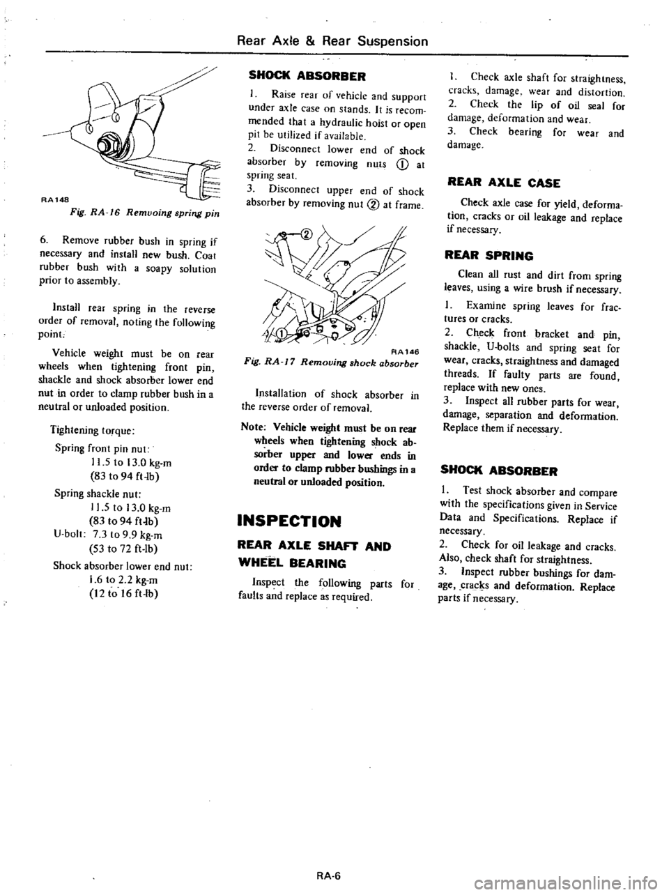
Tightening
torque
Spring
fTont
pin
nut
11
5
to
13
0
kg
m
83
to
94
ft
Ib
Spring
shackle
nut
11
5
to
13
0
kg
m
83
t094
ft
b
U
bolt
7
3
to
9
9
kg
m
S3
to
72
ft
lb
Shock
absorber
lower
end
nut
1
6
to
2
2
kg
m
12
to
16
ft
lb
Rear
Axle
Rear
Suspension
SHOCK
ABSORBER
Raise
rear
of
vehicle
and
support
under
axle
case
on
stands
It
is
recom
mended
that
a
hydraulic
hoist
or
open
pit
be
utilized
if
available
2
Disconnect
lower
end
of
shock
absorber
by
removing
nuts
Q
at
spring
seat
3
Disconnect
upper
end
of
shock
absorber
by
removing
nut
2
at
frame
RA146
Fig
RA
J
7
Removing
shock
absorber
Installation
of
shock
absorber
in
the
reverse
order
of
removal
Note
Vehicle
weight
must
be
on
Tear
wheels
when
tigtrtening
shock
ab
sorber
upper
and
lower
ends
in
order
to
clamp
rubber
bushings
in
a
neutral
or
unloaded
position
INSPECTION
REAR
AXLE
SHAFT
AND
WHEEL
BEARING
Inspect
the
following
parts
for
faults
and
replace
as
required
RA
6
I
Check
axle
shaft
for
straightness
cracks
damage
wear
and
distortion
2
Check
the
lip
of
oil
seal
for
damage
deformation
and
wear
3
Check
bearing
for
wear
and
damage
REAR
AXLE
CASE
Check
axle
case
for
yield
deforma
tion
cracks
or
oil
leakage
and
replace
if
necessary
REAR
SPRING
Clean
all
rust
and
dirt
from
spring
leaves
using
a
wire
brush
if
necessary
1
Examine
spring
leaves
for
frae
tures
or
cracks
2
Check
front
bracket
and
pin
shackle
U
bolts
and
spring
seat
for
wear
cracks
straightness
and
damaged
threads
If
faulty
parts
are
found
replace
with
new
ones
3
Inspect
all
rubber
parts
for
wear
damage
separation
and
deformation
Replace
them
if
necessary
SHOCK
ABSORBER
I
Test
shock
absorber
and
compare
with
the
specifications
given
in
Service
Data
and
Specifications
Replace
if
necessary
2
Check
for
oil
leakage
and
cracks
Also
check
shaft
for
straightness
3
Inspect
rubber
bushings
for
dam
age
cracl
s
and
deformation
Replace
parts
if
necessary
Page 374 of 537
Rear
Axle
Rear
Suspension
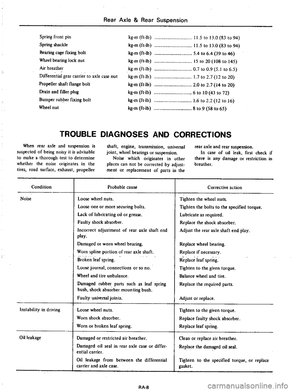
Spring
front
pin
Spring
shackle
Bearing
cage
fIXing
bolt
Wheel
bearing
lock
nut
Air
breather
Differential
gear
carrier
to
axle
case
nut
Propeller
shaft
flange
bolt
Drain
and
filler
plug
Bumper
rubber
fixing
bolt
Wheel
nut
kg
m
ft
lb
kg
m
ft
Ib
kg
en
ft
lb
kg
m
ft
Ib
kg
m
ft
Ib
kg
m
ft
Ib
kg
en
ft
Ib
kg
m
ft
Ib
kg
m
ft
Ib
kg
m
ft
lb
11
5
to
13
0
83
to
94
11
5
to
13
0
83
to
94
S
4
to
6
4
39
to
46
IS
to
20
108
to
l4S
0
7
to
0
9
S
I
to
6
S
17
to
2
7
12
to
20
2
0
to
2
7
14
to
20
6
to
10
43
to
72
1
6
to
2
2
12
to
16
8
to
9
S8
to
6S
TROUBLE
DIAGNOSES
AND
CORRECTIONS
When
rear
axle
and
suspension
is
suspected
of
being
noisy
it
is
advisable
to
make
a
thorough
test
to
determine
whether
the
noise
originates
in
the
tires
road
surface
exhaust
propeller
shaft
engine
transmission
universal
joint
wheel
bearings
or
suspension
Noise
which
originates
in
other
places
can
not
be
corrected
by
adjust
ment
or
replacement
of
parts
in
the
rear
axle
and
rear
suspension
In
case
of
oil
leak
first
check
if
there
is
any
damage
or
restriction
in
breather
Condition
Probable
cause
Noise
Loose
wheel
nuts
Loose
one
or
more
securing
bolts
Lack
of
lubricating
oil
or
grease
Faulty
shock
absorber
Incorrect
adjustment
of
rear
axle
shaft
end
play
Damaged
or
worn
wheel
bearing
Worn
spline
portion
of
rear
axle
shaft
Broken
leaf
spring
Loose
journal
connections
or
so
no
Wheel
and
tire
unbalance
Damaged
rubber
parts
such
as
leaf
spring
bush
shock
absorber
moun
ting
bush
Faulty
universal
joints
Instability
in
driving
Loose
wheel
nuts
Worn
shock
absorber
Worn
or
broken
leaf
spring
Oil
leakage
Damaged
or
restricted
air
breather
Damaged
oil
seal
in
rear
axle
case
or
differ
ential
carrier
Oil
leakage
from
between
the
differential
carrier
and
axle
case
RA
8
Corrective
action
Tighten
the
wheel
nuts
Tighten
the
bolts
to
the
specified
torque
Lubricate
as
required
Replace
the
shock
absorber
Adjust
the
rear
axle
shaft
end
play
Replace
wheel
bearing
Replace
if
necessary
Replace
leaf
spring
Tighten
to
the
given
torque
Balance
wheel
and
tire
Replace
the
required
parts
Adjust
or
replace
Tighten
to
the
given
torque
Replace
faulty
shock
absorber
Replace
leaf
spring
Clean
or
replace
air
breather
Replace
the
damaged
oil
seal
Tighten
to
the
specified
torque
or
replace
gasket
Page 379 of 537
Brake
System
SERVICE
BRAKE
CONTENTS
BRAKE
PEDAL
REMOVAL
INSPECTION
INSTAllATION
MASTER
CYLINDER
REMOVAL
DISASSEMBl
Y
AND
ASSEMBLY
INSPECTION
INSTAllATION
BRAKE
LINE
REMOVAL
INSPECTION
INSTAllATION
N
L
S
V
DESCRIPTION
N
L
S
V
TEST
FRONT
BRAKE
BR
4
BR
4
BR
4
BR
4
BR
5
BR
5
BR
6
BR
6
BR
5
BR
7
BR
B
BR
B
BR
B
BR
9
BR
9
BR
9
BR
lO
BRAKE
PEDAL
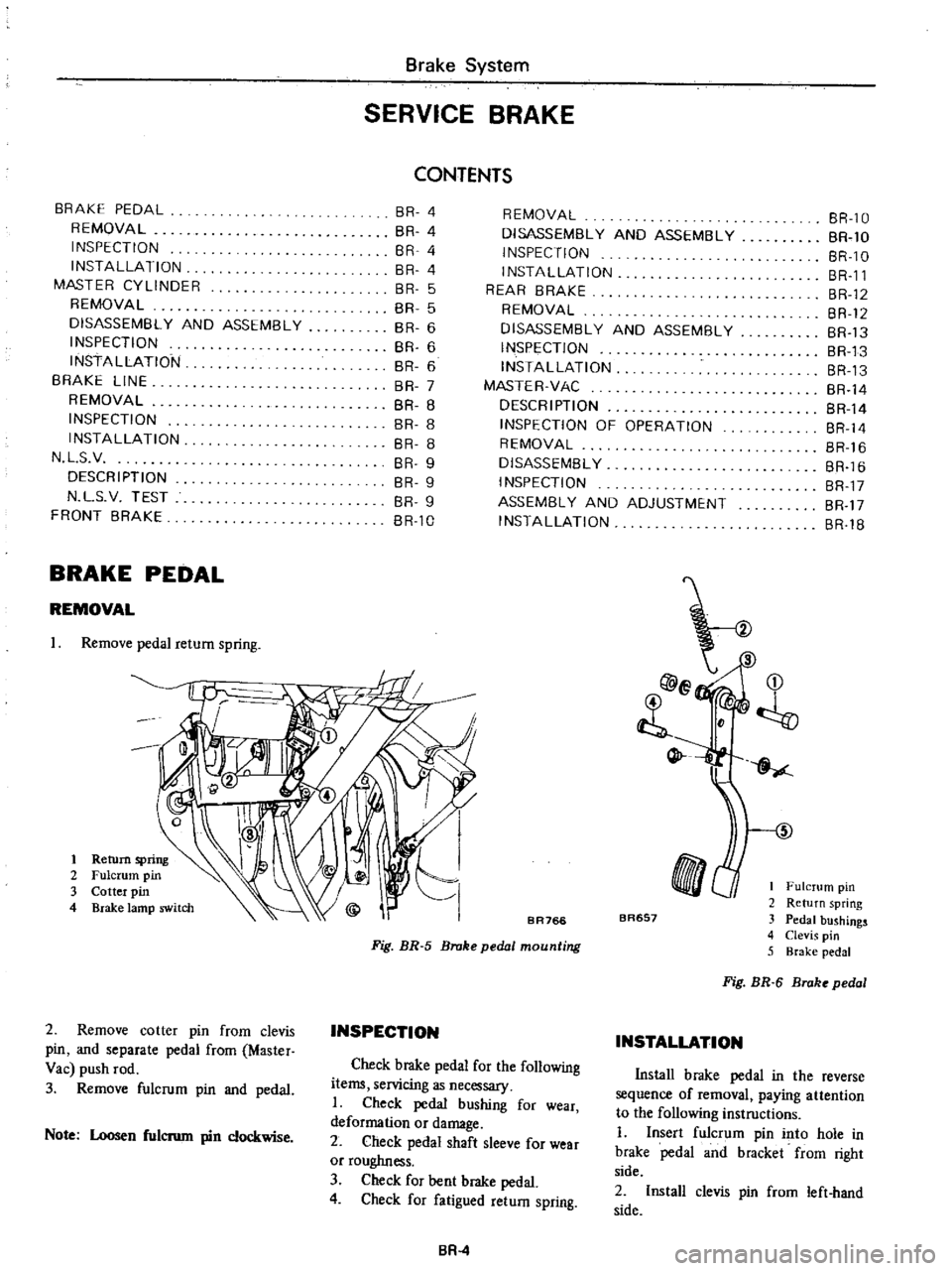
REMOVAL
Remove
pedal
return
spring
I
2
3
4
REMOVAL
DISASSEMBl
Y
AND
ASSEMBLY
INSPECTION
INSTAllATION
REAR
BRAKE
REMOVAL
DISASSEMBLY
AND
ASSEMBLY
INSPECTION
INSTAllATION
MASTER
VAC
DESCRIPTION
INSPECTION
OF
OPERATION
REMOVAL
DISASSEMBLY
INSPECTION
ASSEMBl
Y
AND
ADJUSTMENT
INSTAllATION
BR
lO
BR
1O
BR
lO
BR
ll
BR
12
BR
12
BR
13
BR
13
BR
13
BR
14
BR
14
BR
14
BR
16
BR
16
BR
17
BR
17
BR
IB
b
i
t
I
Fulcrum
pin
2
Return
spring
3
Pedal
bushings
4
Clevis
pin
5
Brake
pedal
5
BR766
BR657
Fig
BR
5
Broke
pedal
mounting
2
Remove
cotter
pin
from
clevis
pin
and
separate
pedal
from
Master
Vac
push
rod
3
Remove
fulcrum
pin
and
pedal
INSPECTION
Fig
BR
6
Broke
pedal
INSTALLATION
Check
brake
pedal
for
the
following
items
servicing
as
necessary
I
Check
pedal
bushing
for
wear
deformation
or
damage
2
Check
pedal
shaft
sleeve
for
wear
or
roughness
3
Check
for
bent
brake
pedal
4
Check
for
fatigued
return
spring
Note
Loosen
fulcnun
pin
clockwise
Install
b
rake
pedal
in
the
reverse
sequence
of
removal
paying
attention
to
the
following
instructions
1
Insert
fulcrum
pin
into
hole
in
brake
pedal
and
bracket
from
right
side
2
Install
clevis
pin
from
left
hand
side
BA
4
Page 381 of 537

DISASSEMBLY
AND
ASSEMBLY
1
00
11I
1
Reservoir
cap
2
Oil
mter
3
Oil
reservoir
4
Packing
5
Valve
cap
Brake
System
00
oC
1
O
b
0
1
r
r
L
BA927
6
Secondary
piston
stopper
7
Bleeder
screw
8
Secondary
return
spring
9
Secondary
piston
10
Primary
return
spring
11
Primary
piston
12
Piston
stopper
13
Piston
stopper
ring
1
Remove
reservoir
cap
and
filter
and
drain
out
brake
fluid
2
Pry
off
stopper
ring
using
a
screwdriver
3
Remove
stopper
screw
and
take
out
stopper
primary
piston
assembly
spring
and
secondary
piston
assembly
in
the
order
shown
Note
Discard
piston
cup
if
it
is
re
moved
from
piston
sembly
and
use
a
new
one
4
Unscrew
plugs
to
gain
access
to
check
valve
for
disassembling
Note
Never
detach
reservoir
tank
U
it
is
removed
for
any
reason
dis
canI
it
and
install
a
new
one
S
Assemble
master
cylinder
in
the
reverse
sequence
of
disassembly
pay
ing
particular
attention
to
the
follow
ing
notes
Fig
BR
10
Master
cylinder
Tightening
torque
Valve
cap
T
okico
8
t09
kg
m
S8
to
6S
ft
Ib
Nabco
2
5
to
3
S
kg
m
18
to
2S
ft
Ib
Bleeder
0
7
to
0
9
kg
m
S
to
7
ft
lb
Notes
a
Replace
gaskets
and
packings
with
new
ones
b
Apply
brake
fluid
or
rubber
grease
to
sliding
contact
surfaces
of
parts
to
facilitate
assembly
of
master
cylinder
c
The
blllke
master
cylinder
is
avail
able
in
both
NABCO
make
and
TOKlCO
make
There
is
no
inter
changeability
of
repair
kits
or
com
ponent
parts
between
NABCO
and
TOKlCO
JIIlkes
When
replacing
the
repair
kit
or
component
parts
BR
6
ascertain
the
brand
of
the
brake
master
cylinder
body
Be
sure
to
use
parts
of
the
same
make
as
the
former
ones
INSPECTION
Thoroughly
clean
all
parts
in
a
suitable
solvent
and
check
for
WOol
or
damaged
parts
Replace
any
part
that
is
faulty
Note
Do
not
clean
robber
parts
with
minerai
oil
since
this
will
be
the
sure
way
of
deteriolllting
parts
Use
brake
fluid
or
alcohoL
When
alco
hol
is
used
for
leaning
these
parts
do
not
immerse
them
in
it
longer
than
30
seconds
After
parts
are
cIeaned
dry
with
compressed
air
I
Check
cylinder
and
position
for
evidence
of
abnonnaI
wear
or
damage
Replace
if
found
faulty
2
Check
piston
to
cylinder
clear
ance
If
it
is
more
than
O
IS
mm
0
OOS9
in
replace
either
piston
or
cylinder
Master
cylinder
inner
diameter
19
0S
mm
Yoin
3
Check
for
weakened
fatigued
or
damaged
springs
and
replace
if
neces
sary
4
When
master
cylioder
is
disassem
bled
be
sure
to
discard
cups
and
valves
Replace
any
other
part
which
shows
evidence
of
deformation
wear
or
damage
S
Replace
damaged
oil
reservoirs
and
caps
INSTALLATION
Install
master
cylinder
in
the
re
verse
sequence
of
removal
Bleed
air
out
of
master
cylinder
by
loosening
bleeder
screw
after
it
is
installed
in
its
original
position
Tightening
torque
Brake
master
cylinder
attaching
nut
0
8
to
1
1
kg
m
6
to
8
ft
Ib
Brake
tube
connector
I
S
to
1
8
kg
m
II
to
13
ft
Ib
Page 383 of 537
REMOVAL
1
Removing
flare
nuts
on
both
ends
and
clips
effects
the
removal
of
brake
tube
and
brake
hose
2
Rear
brake
hose
can
be
removed
by
disconnecting
the
tube
and
then
turning
round
the
hose
Note
When
removing
brake
tubes
and
hoses
use
Flare
Nut
Torque
Wrench
GG943IOOOO
Never
use
an
OpeD
end
or
an
adjust
able
wrench
INSPECTION
1
Examine
all
hoses
for
swell
rubbing
marks
or
ozone
cracking
re
placing
those
found
with
any
of
above
badly
beyond
use
Also
inspect
end
fittings
and
be
sure
that
no
fluid
leak
through
staked
end
has
taken
place
replace
if
necessary
Hose
with
badly
rusted
fitting
should
also
be
replaced
with
a
new
one
2
Clean
all
tubes
to
remove
dust
and
dirt
with
isopropyl
alcohol
check
ing
for
collapse
wear
cracking
swell
or
rusting
Replace
if
foun
d
with
any
of
wove
Use
care
not
to
damage
brake
tubes
while
operation
Check
if
tubes
are
clamped
secure
ly
Mter
all
brake
lines
have
been
installed
retighten
aU
connections
if
necessary
to
assist
in
obtaining
correct
torque
In
retightening
at
front
wheel
cylinder
first
remove
hose
clamp
and
loosen
flare
nut
on
opposite
side
to
avoid
twisting
hose
Hold
pedal
as
far
downward
as
possible
80
kg
176
lb
or
more
examining
evidence
as
to
whether
fluid
is
leaking
through
brake
lines
or
con
nections
Leakage
in
any
manner
can
not
be
permitted
here
In
case
fluid
leaks
tightening
to
specified
torque
tighten
additionally
up
to
2
5
kg
m
J
8
ft
lb
Under
no
circumstances
should
not
be
tightened
over
2
5
kg
m
18
ft
Ib
torque
since
this
elongates
end
fitting
making
it
impossible
to
reuse
brake
tube
Under
no
circumstances
should
rear
brake
hose
and
3
way
connector
be
retightened
over
specified
torques
In
Brake
System
stead
replace
copper
washer
with
a
new
one
after
checking
for
sign
of
damage
on
seating
surface
Never
reuse
an
old
copper
washer
INSTALLATION
Brake
hose
Front
brake
hose
In
installing
brake
hose
first
jack
up
vehicle
to
take
off
the
weight
of
vehicle
from
wheels
so
that
suspension
is
in
rebound
Steering
wheel
should
also
be
kept
in
straight
ahead
position
To
connect
brake
line
first
connect
brake
hose
to
wheel
cylinder
with
the
specified
torque
Tightening
torque
1
7
to
2
0
kg
m
12
to
14
ft
Ib
Then
secure
brake
hose
to
the
bracket
with
lock
plate
so
as
not
to
twist
or
abnormally
bend
the
hose
Note
After
connecting
brake
hose
at
both
eiuIs
pay
keen
attention
not
to
twist
the
hose
when
additional
tightening
is
required
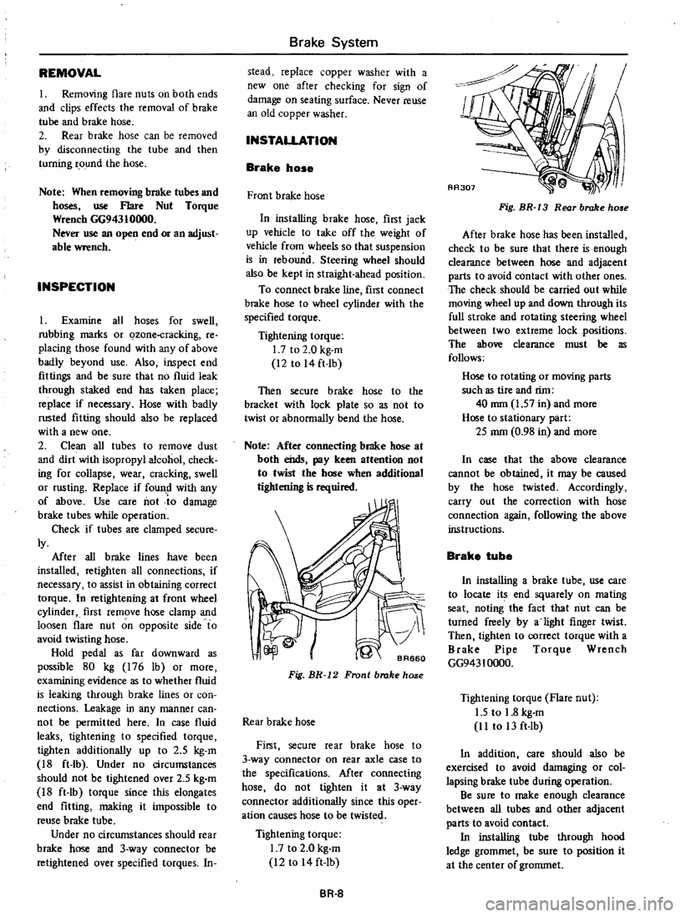
Fig
BR
12
Front
brake
hose
Rear
brake
hose
First
secure
rear
brake
hose
to
3
way
connector
on
rear
axle
case
to
the
specifications
Mter
connecting
hose
do
not
tighten
it
at
3
way
connector
additionally
since
this
oper
ation
causes
hose
to
be
twisted
Tightening
torque
I
7
to
2
0
kg
m
12
to
14
ft
Ib
BR
8
Fig
BR
13
Rear
brake
ho
e
After
brake
hose
has
been
installed
check
to
be
sure
that
there
is
enough
clearance
between
hose
and
adjacent
parts
to
avoid
contact
with
other
ones
The
check
should
be
carried
out
while
moving
wheel
up
and
down
through
its
full
stroke
and
rotating
steering
wheel
between
two
extreme
lock
positions
The
wow
clearance
must
be
as
follows
Hose
to
rotating
or
mOving
parts
such
as
tire
and
rim
40
mm
1
57
in
and
more
Hose
to
stationary
part
2S
mm
0
98
in
and
more
In
case
that
the
above
clearance
cannot
be
obtained
it
may
be
caused
by
the
hose
twisted
Accordingly
carry
out
the
correction
with
hose
connection
again
following
the
above
instructions
Brake
tube
In
installing
a
brake
tube
use
care
to
locate
its
end
squarely
on
mating
seat
noting
the
fact
that
nut
can
be
turned
freely
by
a
light
finger
twist
Then
tighten
to
correct
torque
with
a
Brake
Pipe
Torque
Wrench
GG943
10000
Tightening
torque
Flare
nut
1
5
to
1
8
kg
m
11
to
13
ft
Ib
In
addition
care
should
also
be
exercised
to
avoid
damaging
or
col
lapsing
brake
tube
during
operation
Be
sure
to
make
enough
clearance
between
all
tubes
and
other
adjacent
parts
to
avoid
contact
In
installing
tube
through
hood
ledge
grommet
be
sure
to
position
it
at
the
center
of
grommet
Page 384 of 537
After
connecting
brake
tube
be
sure
to
check
the
clearance
to
prevent
from
damage
The
clearance
at
the
following
portions
must
be
specified
distance
or
more
Tube
to
body
panel
and
frame
Over
5
mm
0
20
in
Tube
to
edge
of
each
panel
Over
10
mm
0
39
in
Tube
to
tube
Loop
pitch
OVer
5
mm
0
20
in
Between
front
tube
and
rear
tube
Over
9
mOl
0
35
in
Tube
to
moving
parts
Over
10
mm
0
39
in
Loop
tube
to
hood
ledge
panel
Over
10
mm
0
39
in
Notes
a
Brake
tubes
are
shaped
at
factory
to
secure
specified
clearance
and
may
not
require
reshaping
Discard
if
they
call
for
excessive
reshaping
b
In
reshaping
a
brake
tube
take
care
to
avoid
damaging
galvanization
or
collapsing
section
Mter
brake
lines
have
been
asssem
bled
check
to
make
sure
that
all
fittings
and
flare
nu
Is
ale
lightened
to
correct
torques
Tightenint
torque
Brake
tube
to
connector
I
Ston
kg
m
II
to
13
ft
Ib
Brake
tube
to
brake
hose
1
7
to
2
0
kg
m
12
to
14
ft
lb
Connector
and
clip
fixing
bolt
O
3S
to
O
4S
kg
m
2
5
to
3
3
ft
lb
3
way
connector
fixing
bolt
on
rear
axle
case
0
8
to
1
1
kg
m
6
to
8
ft
lb
N
L
S
V
DESCRIPTION
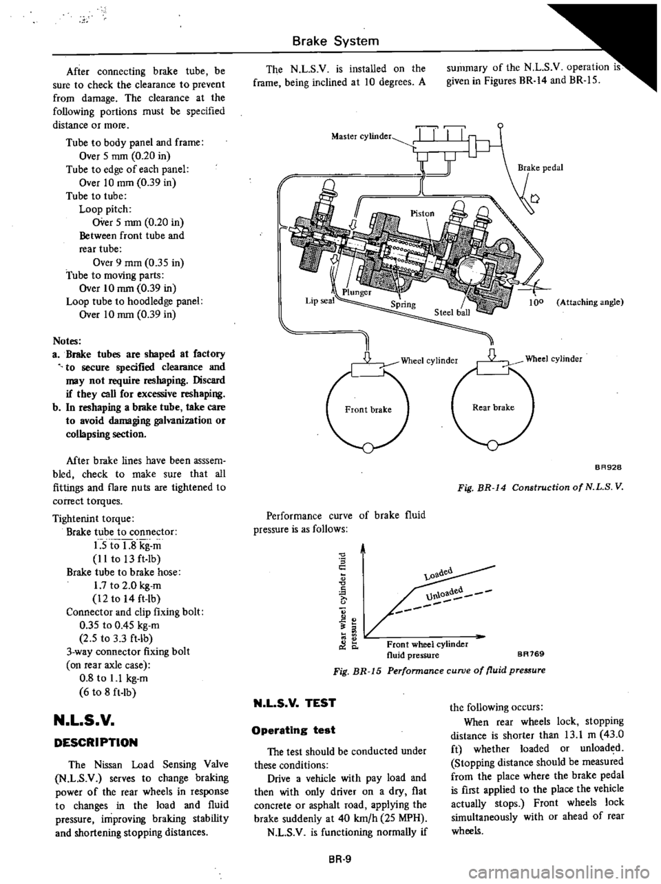
The
Nissan
Load
Sensing
Valve
N
L
S
V
serves
to
change
braking
power
of
the
rear
wheels
in
response
to
changes
in
the
load
and
fluid
pressure
improving
braking
stability
and
shortening
stopping
distances
Brake
System
The
N
L
S
V
is
installed
on
the
frame
being
inclined
at
10
degrees
A
summary
of
the
N
L
S
v
operation
is
given
in
Figures
BR
14
and
BR
15
r
Master
cylinder
TI
II
I
y
1
J
I
l
Attaching
angle
D
Wheel
cylinder
BR928
Fig
BR
14
Construction
of
N
L
S
V
Performance
curve
of
brake
fluid
pressure
is
as
follows
0
S
c
A
0
C
o
l
0
oadea
U1U
Front
wheel
cylinder
fluid
pressure
BR769
Perfonnance
curve
of
fluid
pressure
Fig
BR
15
N
L
S
V
TEST
the
following
occurs
When
rear
wheels
lock
stopping
distance
is
shorter
than
13
1
m
43
0
ft
whether
loaded
or
unloaded
Stopping
distance
should
be
measured
from
the
place
where
the
brake
pedal
is
first
applied
to
the
place
the
vehicle
actually
stops
Front
wheels
lock
simultaneously
with
or
ahead
of
rear
wheels
Operating
test
The
test
should
be
conducted
under
these
conditions
Drive
a
vehicle
with
pay
load
and
then
with
only
driver
on
a
dry
flat
concrete
or
asphalt
road
applying
the
brake
suddenly
at
40
km
h
25
MPH
N
L
S
V
is
functioning
normally
if
BR
9
Page 386 of 537
2
The
allowable
maximum
out
of
round
of
brake
drum
is
0
02
mm
0
0008
in
Re
condition
or
replace
brake
drum
if
specified
limit
is
exceeded
3
Measure
for
tapered
brake
drum
If
specified
limit
of
0
02
mm
0
0008
in
is
exceeded
as
measured
at
a
position
where
the
distance
of
4S
mm
177
in
is
kept
away
from
inlet
re
condition
or
replace
brake
drum
4
Contact
surface
with
which
linings
come
into
contact
should
be
finished
to
such
an
extent
that
it
is
ground
by
a
No
120
to
150
sand
paper
S
Using
a
drum
racer
finish
brake
drum
by
machining
if
it
shows
any
sign
of
score
marks
partial
wear
or
stepped
wear
on
its
contact
surface
Note
After
brake
drum
is
completely
re
conditioned
or
renewed
check
drum
and
shoes
for
proper
contact
pattern
Brake
assembly
I
When
brake
shoe
linings
are
cracked
incompletely
seated
uneven
Iy
worn
andlor
deteriorated
due
to
excessive
heating
or
soiled
with
oil
grease
and
brake
fluid
replace
2
Replace
linings
if
the
thickness
is
worn
down
to
less
than
1
0
mm
0
039
in
Note
When
brake
shoe
lining
is
in
stalled
grind
brake
shoe
lining
face
to
diameter
equal
to
that
of
brake
drum
lining
dimension
Width
x
Thickness
x
Length
4S
x
4
S
x
244
mm
1
77
x
0
177
x
9
61
in
3
Check
adjuster
for
smooth
oper
ation
4
Replace
shoe
return
springs
which
are
broken
or
fatigued
Brake
System
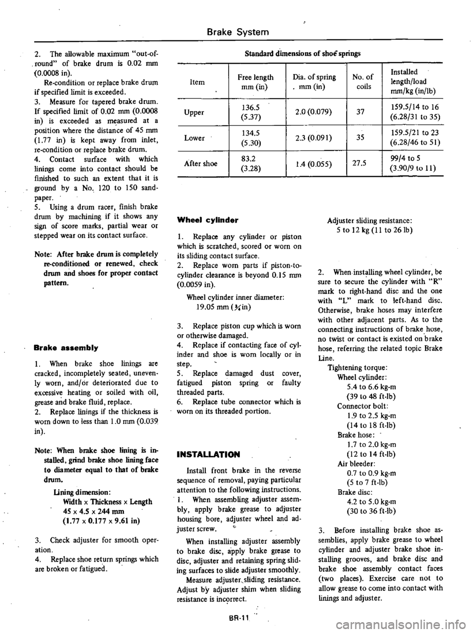
Standard
dimensions
of
shoe
springs
Free
length
Dia
of
spring
No
of
Installed
Item
lengthlload
mOl
in
mOl
in
coils
mm
kg
in
lb
Upper
136
5
2
0
0
079
37
IS9
S
14
to
16
S
37
6
28
31
to
3S
Lower
134
S
2
3
0
091
35
IS9
5
21
to
23
5
30
6
28
46
to
Sl
After
shoe
83
2
1
4
O
OSS
27
S
99
4
to
S
3
28
3
90
9
to
II
Wheel
cylinder
I
Replace
any
cylinder
or
piston
which
is
scratched
scored
or
worn
on
its
sliding
contact
surface
2
Replace
worn
parts
if
piston
to
cylinder
clearance
is
beyond
O
IS
mm
0
OOS9
in
Wheel
cylinder
inner
diameter
19
0S
mOl
Y
in
3
Replace
piston
cup
which
is
worn
or
otherwise
damaged
4
Replace
if
contacting
face
of
cyl
inder
and
shoe
is
worn
locally
or
in
step
S
Replace
damaged
dust
cover
fatigued
piston
spring
or
faulty
threaded
parts
6
Replace
tube
connector
which
is
worn
on
its
threaded
portion
INSTALLATION
Install
front
brake
in
the
reverse
sequence
of
removal
paying
particular
attention
to
the
following
instructions
I
When
assembling
adjuster
assem
bly
apply
brake
grease
to
adjuster
housing
bore
adjuster
wheel
and
ad
juster
screw
When
installing
adjuster
assembly
to
brake
disc
apply
brake
grease
to
disc
adjuster
and
retaining
spring
slid
ing
surfaces
to
slide
adjuster
smoothly
Measure
adjuster
sliding
resistance
Adjust
by
adjuster
shim
when
sliding
resistance
is
in
rrect
BR
ll
Adjuster
sliding
resistance
S
to
12
kg
II
to
261b
2
When
installing
wheel
cylinder
be
sure
to
secure
the
cylinder
with
R
mark
to
right
hand
disc
and
the
one
with
L
mark
to
left
hand
disc
Otherwise
brake
hoses
may
interfere
with
other
adjacent
parts
As
to
the
connecting
instructions
of
brake
hose
no
twist
or
contact
is
existed
on
brake
hose
referring
the
related
topic
Brake
line
Tightening
torque
Wheel
cylinder
SA
to
6
6
kg
m
39
to
48
ft
lb
Connector
bolt
1
9
to
2
5
kg
m
14
to
18
ft
Ib
Brake
hose
1
7
to
2
0
kg
m
12
to
14
ft
lb
Air
bleeder
0
7
to
0
9
kg
m
5
to
7
ft
Ib
Brake
disc
4
2
to
S
O
kg
m
30
to
36
ft
lb
3
Before
installing
brake
shoe
as
semblies
apply
brake
grease
to
wheel
cylinder
and
adjuster
brake
shoe
in
stalling
grooves
and
brake
disc
and
brake
shoe
assembly
contact
faces
two
places
Exercise
care
not
to
allow
grease
to
come
into
contact
with
linings
and
adjuster
Page 388 of 537
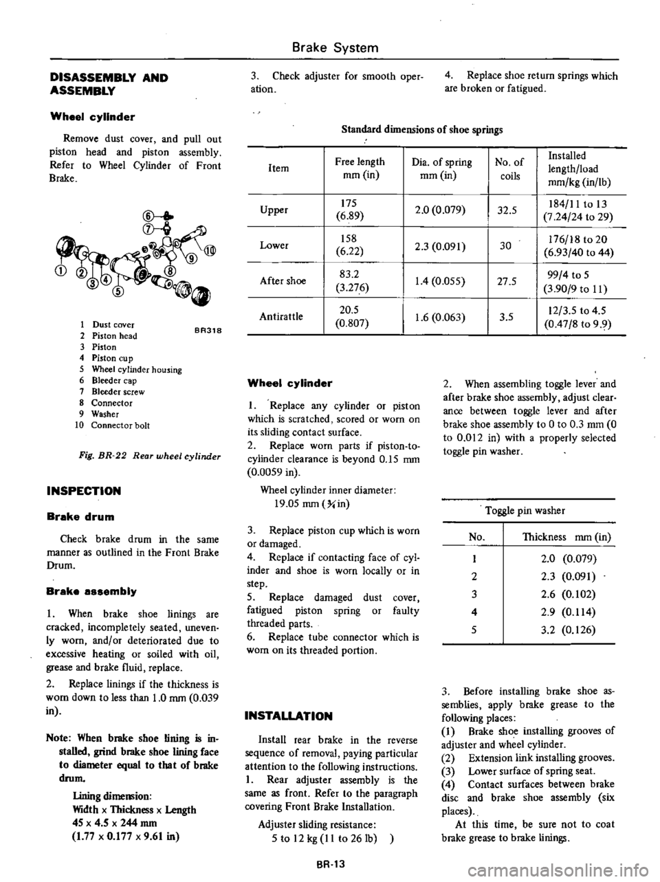
DISASSEMBLY
AND
ASSEMBLY
Wheel
cylinder
Remove
dust
cover
and
pull
out
piston
head
and
piston
assembly
Refer
to
Wheel
Cylinder
of
Front
Brake
CD
l
ID
345
0
1
Dust
cover
2
Piston
head
3
Piston
4
Piston
Cll
p
5
Wheel
cylinder
housing
6
Bleeder
cap
7
Bleeder
screw
8
Connector
9
Washer
10
Connector
bolt
BR318
Fig
BR
22
Rear
wheel
cylinder
INSPECTION
Brake
drum
Check
brake
drum
in
the
same
manner
as
outlined
in
the
Front
Brake
Drum
Brake
assembly
I
When
brake
shoe
linings
are
cracked
incompletely
seated
uneven
ly
worn
andlor
deteriorated
due
to
excessive
heating
or
soiled
with
oil
grease
and
brake
fluid
replace
2
Replace
linings
if
the
thickness
is
WOol
down
to
less
than
1
0
rom
0
039
in
Note
When
brake
shoe
lining
is
in
stalled
grind
brake
shoe
lining
face
to
diameter
equal
10
lha
I
of
brake
drom
Lining
dimemion
Width
x
Thickness
x
Length
4S
x
4
5
x
244
rom
1
77
x
0
177
x
9
61
in
Brake
System
3
Check
adjuster
for
smooth
oper
ation
4
Replace
shoe
return
springs
which
are
broken
or
fatigued
Standard
dimensions
of
shoe
springs
Dia
of
spring
No
of
Installed
Free
length
lengthlload
Item
mOl
in
mOl
in
coils
mmlkg
in
lb
175
2
0
0
079
32
5
184
11
to
13
Upper
6
89
7
24
24
to
29
158
2
3
0
091
30
176
18
to
20
Lower
6
22
6
93
40
to
44
83
2
1
4
0
055
27
5
99
4
to
S
After
shoe
3
276
3
90
9
to
II
20
5
1
6
0
063
3
5
12
3
S
to
4
5
AntiratUe
0
807
0
47
8
to
9
9
Wheel
cylinder
I
Replace
any
cylinder
or
piston
which
is
scratched
scored
or
worn
on
its
sliding
contact
surface
2
Replace
worn
parts
if
piston
to
cylinder
clearance
is
beyond
O
IS
rom
0
00S9
in
Wheel
cylinder
inner
diameter
19
0S
rom
Xin
3
Replace
piston
cup
which
is
worn
or
damaged
4
Replace
if
contacting
face
of
cyl
inder
and
shoe
is
worn
locally
or
in
step
5
Replace
damaged
dust
cover
fatigued
piston
spring
or
faulty
threaded
parts
6
Replace
tube
connector
which
is
worn
on
its
threaded
portion
INSTALLATION
Install
rear
brake
in
the
reverse
sequence
of
removal
paying
particular
attention
to
the
following
instructions
I
Rear
adjuster
assembly
is
the
same
as
front
Refer
to
the
paragraph
covering
Front
Brake
Installation
Adjuster
sliding
resistance
S
to
12
kg
II
to
261b
BR
13
2
When
assembling
toggle
lever
and
after
brake
shoe
assembly
adjust
clear
ance
between
toggle
lever
and
after
brake
shoe
assembly
to
0
to
0
3
mOl
0
to
0
012
in
with
a
properly
selected
toggle
pin
washer
Toggle
pin
washer
No
Thickness
rom
in
I
2
0
0
079
2
2
3
0
091
3
2
6
0
102
4
2
9
0
114
S
3
2
0
126
3
Before
installing
brake
shoe
as
semblies
apply
brake
grease
to
the
following
places
1
Brake
shoe
installing
grooves
of
adjuster
and
wheel
cylinder
2
Extension
link
installing
grooves
3
Lower
surface
of
spring
seat
4
Contact
surfaces
between
brake
disc
and
brake
shoe
assembly
six
places
At
this
time
be
sure
not
to
coat
brake
grease
to
brake
linings