check DATSUN PICK-UP 1977 Service Manual
[x] Cancel search | Manufacturer: DATSUN, Model Year: 1977, Model line: PICK-UP, Model: DATSUN PICK-UP 1977Pages: 537, PDF Size: 35.48 MB
Page 336 of 537
PROPElli
ER
SHAfT
DIFFERENTIAL
G
ARRIERf
Notes
a
PUller
should
be
handled
with
care
in
catchins
the
edge
of
bearing
inner
race
b
Be
careful
not
to
confuse
left
and
right
hand
parts
2
Remove
ring
gear
by
spreading
out
lock
strap
and
loosening
ring
gear
bolts
in
diagonally
3
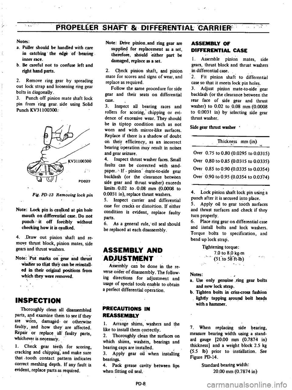
Punch
off
pinion
mate
shaft
lock
pin
from
ring
gear
side
using
Solid
Punch
ICV31100300
KV31100300
PD022
Fig
PD
13
Removing
lock
pin
Note
Lock
pin
i
cauIked
at
pin
hole
mouth
on
differential
case
Do
not
punch
it
off
forCibly
without
checkins
how
it
is
uIked
4
Draw
out
pinion
shaft
and
re
move
thrust
block
pinion
mates
side
gears
and
thrust
washers
Note
Put
marks
on
gear
and
thrust
Wasliersotliat
they
can
be
reinstaD
ed
in
their
original
positions
from
which
they
were
removed
INSPECTION
Thoroughly
clean
all
disassembled
parts
and
examine
them
to
see
if
they
8re
worn
damaged
or
otherwise
faulty
and
how
they
are
affected
Repair
or
replace
ail
faulty
parts
whichever
is
necessaiy
I
Check
gear
teeth
for
scoring
cracking
and
chipping
and
make
sure
that
tooth
contact
pattern
indicates
correct
meshing
depth
If
any
fault
is
evident
replace
parts
as
required
Note
Drive
pinion
and
ring
gear
are
supplied
for
replacement
as
a
set
therefore
should
either
part
be
damaged
replace
as
a
set
2
Check
pinion
shaft
and
pinic
m
mate
for
scores
and
signs
of
wear
and
replace
as
required
Follow
the
same
procedure
for
side
gear
and
their
seats
on
differential
case
3
Inspect
all
bearing
races
and
rollers
for
scoring
chipping
or
evi
dence
of
excessive
wear
They
should
be
in
tiptop
condition
such
as
not
worn
and
with
mirror
like
surfaces
Replace
if
there
is
a
shadow
of
doubt
oil
their
efficiency
as
an
incorrect
bearing
operation
may
result
in
noises
and
gear
seizure
4
Inspect
thrust
washer
faces
Small
faults
can
be
corrected
with
sand
paper
If
pinion
mate
to
ide
gear
backlash
or
the
clearance
between
side
gear
and
thrust
washer
exceeds
limits
0
02
to
0
08
nun
0
0008
to
0
0031
in
replace
thrust
washers
S
Inspect
carrier
and
differential
case
for
cracks
or
distortion
If
either
condition
is
evident
replace
faulty
parts
6
As
a
general
rule
oil
seal
should
be
replaced
at
each
disassembly
ASSEMBLY
AND
ADjUSTMENT
Assembly
can
be
done
in
the
reo
verse
order
of
disassembly
The
foDow
ing
directions
for
adjustment
and
usage
of
special
tools
enable
to
obtain
a
perfect
differential
operation
PRECAUTIONS
IN
REASSEMBLY
I
Arrange
shims
w
shers
and
the
like
to
install
them
correctly
2
Thoroughly
clean
the
surfaces
on
which
shims
washers
bearings
and
bearing
caps
are
installed
3
Apply
gear
oil
when
installing
bearings
4
Pack
grease
cavity
between
lips
when
fitting
oil
seal
PD
8
ASSEMBLY
OF
DIFFERENTIAL
CASE
I
Assemble
pinion
mates
side
gears
thrust
block
and
thrust
washers
in
differential
case
2
Fit
pinion
shaft
to
differential
case
so
that
it
meets
lock
pin
holes
3
Adjust
pinion
mate
to
ide
gear
backlash
or
the
clearance
between
the
rear
face
of
side
gear
and
thrust
washer
to
0
02
to
0
08
mOl
0
0008
to
0
0031
in
by
selecting
side
gear
thrust
washer
Side
gear
thrust
WlISber
Thickness
nun
in
Over
0
7S
to
0
80
0
029S
to
0
03IS
Over
0
80
to
O
8S
Om
IS
to
0
033S
Over
0
8S
to
0
90
0
033S
to
0
03S4
Over
0
90
to
0
9S
0
03S4
to
0
0374
4
Lock
pinion
shaft
lock
pin
using
a
punch
after
it
is
secured
into
place
S
Apply
oil
to
gear
tooth
surfaces
and
thrust
surfaces
and
check
if
they
turn
properly
6
Place
ring
gear
on
differential
case
and
install
bolts
and
lock
washers
Torque
bolts
to
specification
and
bend
up
lock
strap
Tightening
torque
7
0
to
8
0
kg
m
S1to
Sifft
Ib
Notes
ao
Use
only
genuine
ring
gear
bolts
and
new
lock
strap
b
Tighten
bolts
in
criss
cross
fashion
lighdy
tapping
fOund
bolt
heac
Js
with
a
hammer
7
When
replacing
side
bearing
measure
bearing
width
using
a
stand
ard
gauge
20
00
nun
0
7874
in
thickness
and
a
weight
block
2
5
kg
S
S
Ib
prior
to
installation
See
Figure
PD
I4
Standard
bearing
width
20
00
nun
0
7874
in
Page 338 of 537
PROPELLER
SHAFT
DIFFERENTIAL
CARRIER
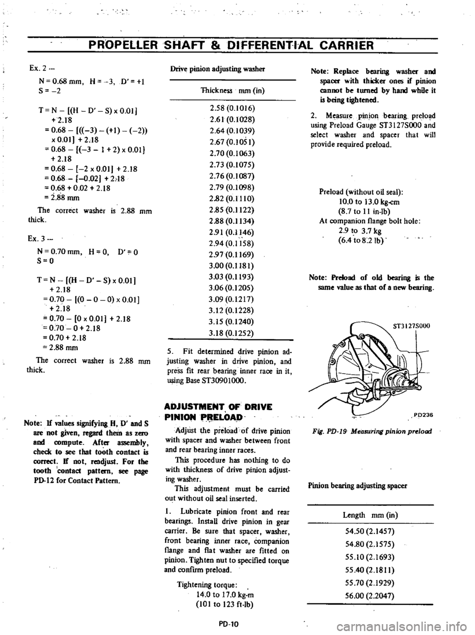
Ex
2
N
O
68mm
H
3
D
I
S
2
T
N
H
0
S
x
0
01
2
18
0
68
3
1
2
x
Om
2
18
0
68
3
1
2
x
0
01
2
18
0
68
2
x
0
01
2
18
0
68
0
02
N8
0
68
0
02
2
18
i
88
mm
The
correct
washer
is
2
88
mm
thick
Ex
3
N
0
70mm
H
O
0
0
S
O
T
N
H
0
S
x
0
01
2
18
0
70
0
0
0
x
0
01
2
18
0
70
0
x
0
01
2
18
0
70
0
2
18
0
70
2
18
2
88
mm
The
correct
washer
is
2
88
mm
thick
Note
If
lues
signifying
H
D
and
S
are
not
given
regard
them
as
zero
and
n
C
r
e
After
assembly
check
to
see
that
tooth
contact
is
correct
If
not
readjust
For
the
tooth
contact
pattern
see
page
PJ
12
for
Contact
Pattern
Drive
pinion
adjusting
washer
Thickness
mm
in
2
58
0
1016
2
61
0
1028
2
64
0
1039
2
67
0
1051
2
70
0
1063
2
73
0
107S
2
76
0
1087
2
79
0
1098
2
82
0
1110
2
85
OJ
122
2
88
OJ
134
2
91
0
1146
2
94
0
1IS8
2
97
0
1169
3
00
0
1181
3
03
0
1
193
3
06
0
1205
3
09
0
1217
3
12
0
1228
3
IS
0
1240
3
18
0
I2S2
S
Fit
determined
drive
pinion
ad
justing
washer
in
drive
pinion
and
preSs
fit
rear
bearing
inner
race
in
it
using
Base
ST30901000
ADJUSTMENT
OF
DRIVE
PINIONPI
IELOAD
AdjUst
the
preload
of
drive
pinion
with
spacer
and
washer
between
front
and
rear
bearing
inner
races
This
procedure
has
nothing
to
do
with
thickness
of
drive
pinion
adjust
ing
washer
This
adjustment
must
be
carried
out
without
oil
seal
inserted
I
Lubricate
pinion
front
and
rear
bearings
Install
drive
pinion
in
gear
carrier
Be
sure
that
spacer
t
washer
front
bearing
inner
race
Companion
flange
and
flat
washer
are
fitted
on
pinion
Tighten
nut
to
specified
torque
and
confum
preload
Tightening
torque
14
0
to
17
0
kg
m
101
to
123
ft
lb
PD
l0
Note
Replace
bearing
washer
and
spacer
with
thicker
ones
if
pinion
cannot
be
turned
by
hand
while
it
is
heing
tightened
2
Measure
pinion
bearing
prelo
d
using
Preload
Gauge
ST3I
27S000
and
select
washer
and
spacer
that
will
provide
required
preload
Preload
without
oil
seal
10
0
to
13
0
kg
cm
8
7
to
II
in
lb
At
companion
flange
bolt
hole
2
9
to
3
7
kg
6
4
to8
2Ib
Note
Preload
of
old
bearing
is
the
same
value
as
that
of
a
new
bearing
Fig
PD
19
Measuring
pinion
preload
Pinion
bearing
adjusting
spacer
Length
mOl
in
S4
50
2
14S7
S4
80
2
IS7S
SS
IO
2
1693
5S
40
2
1811
SS
70
2
1929
S6
00
2
2047
Page 339 of 537
PROPELLER
SHAFT
DIFFERENTIAL
CARRIER
Drive
pinion
bearing
adjusting
washer
Thickness
mm
in
over
3
80
to
3
82
0
1496
to
O
lS04
over
3
82
to
3
84
O
lS04
to
0
ISI2
over
3
84
to
3
86
O
lSI2
to
0
IS20
over
3
86
to
3
88
O
lS20
to
O
IS28
over
3
88
to
3
90
O
lS28
to
0
IS3S
over
3
90
to
3
92
0
IS3S
to
O
IS43
over
3
92
to
3
94
0
IS43
to
O
lSS
I
over
3
94
to
3
96
O
lSSI
to
O
lS59
over
3
96
to
3
98
O
lSS9
to
0
IS67
over
3
98
to
4
00
O
lS67
to
O
lS7S
over
4
00
to
4
02
0
S7S
to
O
lS83
over
4
02
to
4
04
O
lS83
to
0
IS91
over
4
04
to
4
06
O
lS9I
to
0
IS98
over
4
06
to
4
08
O
lS98
to
0
1606
over
4
08
to
4
10
0
1606
to
0
1614
3
Check
and
adjust
tooth
contact
pattern
when
former
adjustment
of
bearing
preload
is
completed
Unless
anything
wrong
is
found
remove
drive
pinion
nut
and
companion
flange
and
press
n
oil
seal
into
gear
carrier
using
Oil
Seal
Fitting
Tool
KV38I02SS0
Apply
grease
cavity
be
tween
seal
lips
4
Again
install
companion
flange
and
washer
and
tighteh
nut
to
speci
fied
torque
14
0
to
17
0
kg
m
IO
to
123
ft
lb
S
Measure
preload
again
Preload
with
oil
seal
I
1
0
to
14
0
kg
cm
9
S
to
12
in
lb
At
companion
flange
bolt
hole
3
1
to
4
0
kg
6
8
to
8
81b
ADJUSTMENT
OF
SIDE
BEARING
SHIMS
I
If
hypoid
gear
set
carrier
dif
ferential
case
or
side
bearing
has
been
replaced
with
new
one
adjust
the
side
bearing
preload
with
adjusting
shim
The
required
thickness
of
adjusting
shim
can
be
calculated
by
the
follow
ing
formulas
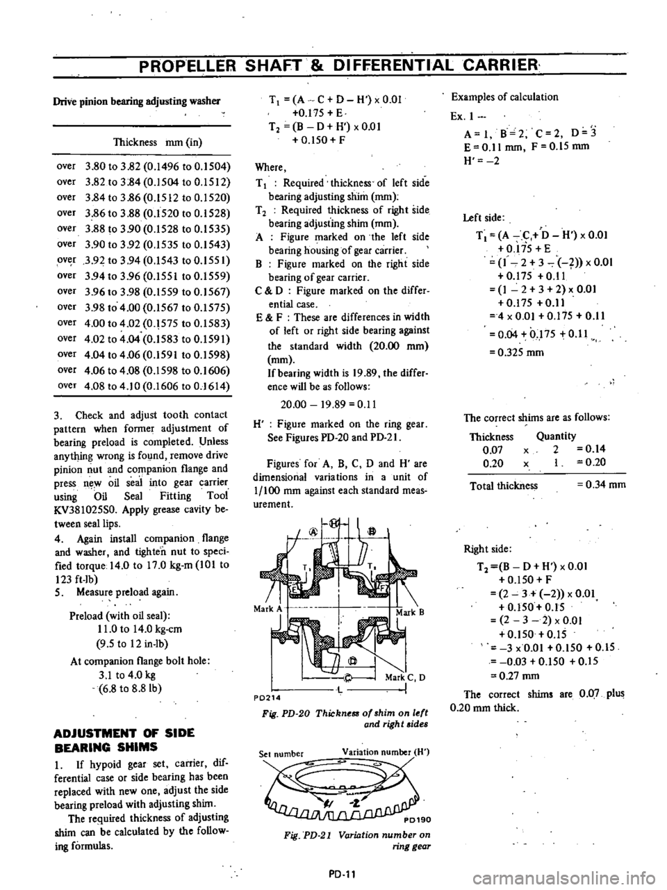
T
A
C
D
H
xO
OI
O
l7S
E
T2
B
D
H
xO
OI
O
ISO
F
Where
T
1
Required
thickness
of
left
side
bearing
adjusting
shim
mm
T
2
Required
thickness
of
right
side
bearing
adjusting
shim
mm
A
Figure
marked
on
the
left
side
bearing
housing
of
gear
carrier
B
Figure
marked
on
the
right
side
bearing
of
gear
carrier
C
0
Figure
marked
on
the
differ
entia
case
E
F
These
are
differences
in
width
of
left
or
right
side
bearing
against
the
standard
width
20
00
mOl
mOl
If
bearing
width
is
19
89
the
differ
ence
will
be
as
follows
20
00
19
89
0
11
H
Figure
marked
on
the
ring
gear
See
Figures
PD
20
and
PD
2
I
Figures
for
A
B
C
0
and
H
are
dimensional
varia
tions
in
a
unit
of
1
100
mm
against
each
standard
meas
urement
f
@
a
rj
71
Markj
Mark
B
Mark
C
0
P0214
Fig
PD
20
Thickn
of
shim
on
l
ft
and
righ
t
sides
Fig
PD
21
Variation
number
on
ring
gear
PD
ll
Examples
of
calculation
Ex
I
A
I
B
2
C
2
0
3
E
0
11
mm
F
O
IS
mm
H
2
Left
side
T
A
C
0
H
x
0
01
O
liS
E
1
2
3
1
x
0
01
0
17S
0
11
1
2
3
2
x
O
O
O
l7S
0
11
4
x
0
01
0
175
0
11
0
04
0
1
7S
0
11
0
32S
mOl
The
correct
shims
are
as
follows
Thickness
0
07
0
20
Quantity
x
2
0
14
x
I
0
20
Total
thickness
0
34
mOl
Right
side
T2
B
0
H
x
0
01
O
lSO
F
2
3
2
x
0
01
O
ISO
0
15
2
3
2
x
0
01
O
ISO
0
15
3
x
O
OI
O
ISO
O
IS
0
03
O
lSO
O
lS
0
27
mm
The
correct
shims
are
0
07
plus
0
20
mm
thick
Page 340 of 537
PROPELLER
SHAFf
DIFFERENTIAL
CARR
IER
Ex
2
A
0
B
3
C
I
0
0
E
0
20
mOl
F
0
17
mOl
H
2
Left
side
T
I
A
C
D
H
x
om
0
17S
E
0
I
0
2
x
0
01
0
I7S
0
20
0
I
0
2
x
0
01
0
17S
0
20
3
Om
0
17S
0
20
0
03
0
17S
0
20
O
34S
mrn
The
correct
shinjs
are
O
OS
plus
0
10
plus
0
20
mrn
thick
Right
side
T2
B
D
H
xO
0l
O
ISO
F
3
0
2
x
om
O
ISO
0
17
3
0
2
x
om
0
150
0
17
S
x
0
01
0
ISO
0
I7
O
OS
0
1S0
0
17
0
37
mrn
The
correct
shims
are
0
07
plus
0
1
0
plus
0
20
mm
thick
Note
If
w1ues
signifying
A
B
C
0
and
H
are
not
given
regard
them
as
zero
and
compute
Aft
assembly
check
to
see
that
preload
and
backlash
are
correct
If
not
readjust
Side
bearing
adjusting
shim
Thickness
mm
in
O
OS
0
0020
0
07
0
0028
0
1
0
0
0039
0
20
0
0079
0
50
0
0197
2
Fit
determined
side
bearing
adjusting
shim
on
differential
case
and
press
fit
left
and
right
side
bearing
inner
races
on
it
using
Side
Bearing
Drift
ST33230000
and
Adapter
ST33061000
3
Install
differential
case
assembly
into
gear
carrie
tapping
with
a
rubber
mallet
4
Align
mark
on
bearing
cap
with
that
on
gear
carrier
and
install
bearing
cap
on
carrier
And
tight
n
bolts
to
specified
torque
Tightening
torque
4
0
to
S
O
kg
m
29
to
36
fHb
S
Measure
ring
gear
to
drive
pinion
backlash
If
backlash
is
too
small
remove
shims
from
left
side
and
add
them
to
right
side
To
reduce
backlash
remove
shims
from
right
side
and
add
them
to
left
side
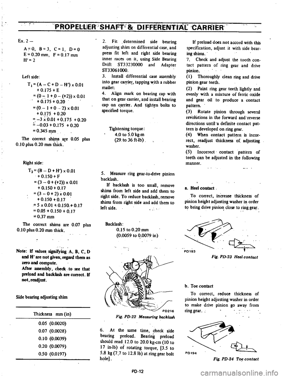
Backlash
O
1S
to
0
20
mrn
0
00S9
to
0
0079
in
Fig
PD
22
Mccuuring
back1aah
6
At
the
same
time
check
side
bearing
preload
Bearing
preload
should
read
12
0
to
20
0
kg
cm
10
to
17
in
lb
of
rotating
torque
3
S
to
S
8
kg
7
7
to
12
8
Ib
at
ring
gear
bolt
hole
PD
12
If
preload
does
not
accord
with
this
specification
adjust
it
with
side
bear
ing
shims
7
Check
and
adjust
the
tooth
con
tact
pattern
of
ring
gear
and
drive
pinion
I
Thoroughly
clean
ring
and
drive
pinion
gear
teeth
2
Paint
ring
gear
teeth
lightly
and
evenly
with
a
mixture
of
ferric
oxide
and
gear
oil
to
produce
a
contact
pattern
3
Rotate
pinion
through
several
revolutions
in
the
forward
and
reverse
directions
until
a
defmite
contact
pat
tern
is
developed
on
ring
gear
4
When
contact
pattern
is
incor
rect
readjust
thickness
of
adjusting
washer
S
Incorrect
contact
pattern
of
teeth
can
be
adjusted
in
the
following
manner
a
Heel
contact
To
correct
increase
thickness
of
pinion
height
adjusting
washer
in
order
to
bring
drive
pinio
close
to
ring
gear
P0193
Fig
PD
23
Hul
contact
b
Toe
contact
To
correct
reduce
thickness
of
pinion
height
adjusting
washer
in
order
to
make
drive
pinion
go
away
from
ring
gear
P0194
1
Fig
PD
24
To
contact
Page 352 of 537
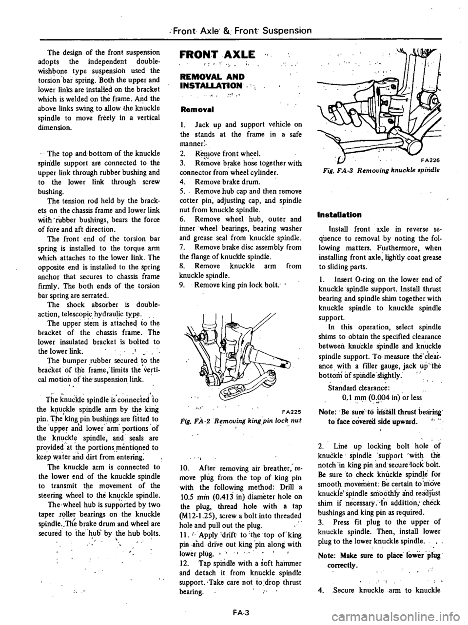
The
design
of
the
front
suspension
adopts
the
independent
double
wishbone
type
suspension
used
the
torsion
bar
spring
Both
the
upper
and
lower
links
are
installed
on
the
bracket
which
is
welded
on
the
frame
A
1d
the
above
links
swing
to
allow
the
knuckle
spindle
to
move
freely
in
a
vertical
dimension
The
top
and
bottom
of
the
knuckle
spindle
support
are
connected
to
the
upper
link
through
rubber
bushing
and
to
the
lower
lick
through
screw
bushing
The
tension
rod
held
by
the
brack
ets
on
the
chassis
frame
and
lower
lick
wiih
rubber
bushings
bears
the
force
of
fore
and
aft
direction
The
front
end
of
the
torsion
bar
spring
is
installed
to
the
torque
arm
which
attaches
to
the
lower
link
The
opposite
end
is
installed
to
the
spring
anchor
that
secures
to
chassis
frame
firmly
The
both
ends
of
the
torsion
bar
spring
are
serrated
The
shock
absorber
is
double
action
telescopic
hydraulic
type
The
upper
stem
is
attached
to
the
bracket
of
the
chassis
frame
The
lower
insulated
bracket
is
bolted
to
the
lower
lick
The
bumper
rubber
secured
to
the
bracket
Of
the
frame
limits
the
verti
cal
motion
of
the
suspension
lick
The
knuckle
spindle
is
connecied
to
the
k
ufkle
spindle
arm
by
the
king
pin
The
king
pin
bushings
are
fitted
to
the
upper
and
lower
arm
portIOns
of
the
knuckle
spindle
and
seals
are
provided
at
the
portions
mentioned
to
keep
water
and
dirt
from
enteri
g
The
knuckle
arm
is
connected
to
the
lower
end
of
the
knuckle
spindle
to
transmit
ttLe
movement
of
the
steering
wheel
to
the
knuckle
spindle
The
wheel
hub
is
supported
by
two
taper
roller
bearings
on
the
knuckle
spindle
Tlie
brake
drum
and
wheel
are
secured
to
ihe
hub
by
the
hub
bolts
Front
Axle
Front
Suspension
FRONT
AXLE
REMOVAL
AND
INSTALLATION
Removal
I
Jack
up
and
support
vehicle
on
the
stands
at
the
frame
in
a
safe
manner
2
Remove
front
wheel
3
Re
ove
brake
hose
together
with
connector
from
wheel
cylinder
4
Remove
brake
drum
S
Remove
hub
cap
and
then
remove
cotter
pin
adjusting
cap
and
spindle
nut
from
knuckle
spindle
6
Remove
wheel
hub
outer
and
inner
wheel
bearings
bearing
washer
and
grease
seal
from
knuckle
spindle
7
Remove
brake
disc
assembly
from
the
flange
of
knuckle
spindle
8
Remove
knuckle
arm
from
knuckle
spindle
9
Remove
king
pin
lock
bolt
FA225
Fig
FA
R
mol1ing
king
pin
loch
nut
10
After
removing
air
breather
re
move
plug
from
the
top
of
king
pin
with
the
following
method
Drill
a
10
5
mm
0
413
in
diameter
hole
on
the
plug
thread
hole
with
a
tap
M
12
1
2S
screw
a
bolt
into
threaded
hole
and
pull
out
the
plug
II
Apply
drift
to
the
top
of
king
pin
and
drive
out
king
pin
along
with
lower
plug
12
Tap
spindle
with
a
soft
haJnmer
and
detach
it
from
knuckle
spindle
support
Take
care
not
io
drop
thrust
bearing
FA
3
FA226
Fig
FA
3
R
moving
knuckle
piridle
Installation
Install
front
axle
in
reverse
se
quence
to
removal
by
noting
the
fol
lowing
matters
Furthermore
when
installing
front
axle
lightly
coat
grease
to
sliding
parts
I
Insert
O
ring
on
the
lower
end
of
knuckle
spindle
support
Install
thrust
bearing
and
spindle
shim
together
with
knuckle
spindle
to
knuckle
spindle
support
In
this
operation
select
spindle
shims
to
obtain
the
specified
clearance
between
knuckle
spindle
and
knuckle
spindle
support
To
measure
the
Clear
ance
with
a
filler
gauge
jack
up
the
bottom
of
spindle
slightly
Standard
clearance
0
1
mOl
0
004
in
or
less
Note
Be
sure
to
iristsll
thrust
bearing
to
face
coverea
side
upward
2
Line
up
locking
bolt
hole
of
knuckle
spindle
support
with
the
notch
in
king
pin
and
secure
lock
bolt
Be
sure
to
check
killJckle
spindle
for
smooth
movement
Be
certain
to
move
knuckie
spindle
smoothly
and
reailjust
shim
if
necessary
In
addition
check
bushings
and
king
pin
as
required
3
Press
fit
plug
to
the
upper
of
knuckle
spindle
Then
install
lower
plug
to
the
lower
knuckle
spindle
Note
Make
sure
to
place
lower
plug
conectly
4
Secure
knuckle
arm
to
knuckle
Page 353 of 537

spindle
and
torque
bolt
to
10
3
to
12
1
kg
m
75
to
88
ft
lb
Bend
lock
plate
to
engaged
flats
on
boll
head
Note
When
disassembled
discard
used
lock
plate
5
Pack
grea
to
the
upP
r
and
lower
bushings
on
knuckle
spindle
until
grease
c
omes
out
from
gr
ease
seal
6
Fill
wheel
hub
and
cap
with
grease
up
to
the
described
level
See
Figure
F
A
4
FA141
Fig
FA
4
Gre
ing
wheel
hub
7
Pack
roller
and
cone
assembly
and
the
cavity
of
grease
seal
lip
with
grease
8
Coat
grease
to
the
thread
of
knuckle
spindle
bearing
washer
and
bearing
lock
nul
9
Secure
wheel
hub
bearings
bear
ing
washer
and
spindle
nut
on
knuckle
spindle
and
adju
t
bearing
preload
referring
to
the
paragraph
Wheel
bearing
adjustment
Note
Be
sure
to
obtain
correct
pre
load
on
wheel
bearings
for
the
pu
rpose
of
ving
their
long
life
taking
care
to
keep
wheel
be8rlngs
grease
seal
bearing
washer
and
spin
dle
nut
clean
when
installing
them
WHEEL
BEARING
D
TM
NT
Wrong
adjustment
of
wheel
bear
ing
causes
abnonnal
wear
and
score
on
the
bearings
and
knuckle
spindle
Front
Axle
Front
Suspension
To
attain
proper
preload
on
wheel
bearings
proceed
the
following
opera
tions
I
Torque
spindle
nut
to
3
0
to
3
S
kg
m
22
to
25
ft
lb
using
torque
wrench
FA227
Fig
FA
5
Tightening
apindle
nut
2
Rotate
wheel
hub
a
few
turns
clockwise
and
counterclockwise
to
seat
bearings
Then
retighten
spindle
nut
to
the
same
tightening
torque
Be
certain
to
rotate
hub
smoothly
3
Back
off
spindle
nut
in
range
from
40
to
70
degrees
Locate
adjust
ing
cap
on
spindle
nut
so
as
to
align
the
castellation
on
the
cap
with
the
cotter
pin
hole
in
the
spindle
4
Check
the
hub
rotation
If
hub
rotates
properly
measure
bearing
rota
tion
starting
torque
If
measured
torque
is
deviated
from
the
specified
value
r
place
beari
gs
r
re
dju
st
The
starting
torque
can
be
mea
sured
by
a
spring
balance
as
shown
in
Figure
F
A
6
Spring
balance
indication
at
hub
bolt
New
bearing
2
1
kg
4
Ib
o
ess
Used
bearing
1
0
kg
2
2
lb
or
less
Notes
a
When
measuring
the
starting
force
pull
the
spring
balance
toward
tan
gential
direction
against
normal
line
connected
between
hub
boll
and
spindle
center
b
Axial
play
is
permissible
to
exist
in
0
1
mm
0
004
in
or
less
FA
4
fA22S
Fig
FA
6
Mea
uring
bearing
rotation
atarting
torque
S
Install
a
new
cotter
pin
Bend
the
ends
of
coller
pin
around
the
castel
lated
flange
of
adjusting
cap
Then
install
hub
cap
DISASSEMBLY
AND
ASSEMBLY
Knuckle
spindle
I
Drive
spindle
bushing
and
grease
seal
out
of
knuckle
spindle
with
KiTlg
Pin
Bush
Drift
ST3S380000
Discard
bushing
and
grease
seal
when
disas
sembled
2
After
cleaning
king
pin
bores
thoroughly
install
bushing
carefully
by
using
the
above
special
tpol
Posi
tion
bushing
in
accordance
With
the
instructions
fIlled
in
Figure
F
A
7
and
FA
8
34
mm
1
34
in
Upper
side
in
lower
boss
I
I
1
II
I
Pla
ce
this
position
in
line
with
grease
nipple
hole
Upper
side
in
upper
boss
FA229
Fig
FA
7
King
pin
bu
hing
Page 354 of 537
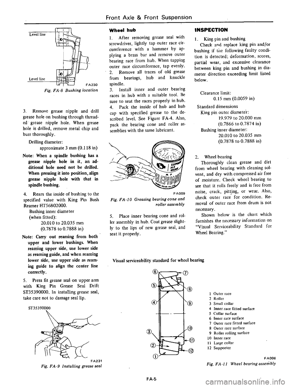
Level
line
Level
line
FA230
Fig
FA
8
Bushing
location
3
Remove
grease
nipple
and
drill
grease
hole
on
bushing
through
thread
ed
grease
nipple
hole
When
grease
hole
is
drilled
remove
metal
chip
and
burr
thoroughly
Drilling
diameter
approximate
3
mOl
0
118
in
Note
When
a
spindle
bushing
has
a
grease
nipple
hole
in
it
an
ad
ditional
hole
need
not
be
drilled
When
pressing
it
into
position
align
grease
nipple
hole
with
that
in
spindle
bushing
4
Ream
the
inside
of
bushing
to
the
specified
value
with
King
Pin
Bush
Reamer
HT56802000
Bushing
inner
diameter
when
fitted
20
010
to
20
03S
mOl
0
7878
to
0
7888
in
Note
Carry
out
reaming
from
both
upper
and
lower
bushings
When
reaming
upper
side
use
lower
side
as
reaming
guide
and
when
reaming
lower
side
use
upper
side
as
ream
ing
guide
to
align
the
center
line
correctly
5
Press
fit
grease
seal
on
upper
arm
with
King
Pin
Grease
Seal
Drift
ST35390000
In
installing
grease
seal
take
care
not
to
damage
seal
lip
51
35390000
FA231
Fig
FA
9
Installing
grease
seal
Front
Axle
Front
Suspension
Wheel
hub
1
After
removing
grease
seal
with
screwdriver
lightly
tap
outer
race
cir
cumference
with
a
hammer
by
ap
plying
a
brass
bar
and
remove
outer
bearing
race
from
hub
When
tapping
outer
race
circumference
tap
evenly
2
Remove
all
traces
of
old
grease
from
bearings
hub
and
knuckle
spindle
3
Install
inner
and
outer
bearing
races
in
hub
with
a
suitable
tool
Be
sure
to
seat
the
races
properly
in
hub
4
Pack
the
inside
of
hub
and
hub
cap
with
specified
grease
to
the
de
scribed
level
See
Figure
FAA
Also
pack
the
bearing
cone
and
roller
as
semblies
with
the
same
lubricant
FA009
Fig
FA
10
Greasing
bearing
cone
and
roller
assembly
5
Place
inner
bearing
cone
and
rol
ler
assembly
in
hub
Coat
grease
slight
ly
to
the
lips
of
new
grease
seal
and
seat
it
properly
INSPECTION
King
pin
and
bushing
Check
and
replace
king
pin
andlor
bushing
if
tne
following
faulty
condi
tion
is
detected
deformation
scores
partial
wear
and
excessive
clearance
between
king
pin
and
bushing
in
dia
meter
direction
exceeding
limit
listed
below
Clearance
limit
0
15
mOl
0
00S9
in
Standard
dimensions
King
pin
outer
diameter
19
979
to
20
000
mm
0
7866
to
0
7874
in
Bushing
inner
diameter
20
010
to
20
035
mOl
0
7878
to
0
7888
in
2
Wheel
bearing
ThorougWy
clean
grease
and
dirt
from
wheel
bearing
with
cleaning
sol
vent
and
dry
with
compressed
air
free
of
moisture
Check
wheel
bearing
to
see
that
it
rolls
freely
and
is
free
from
noise
crack
pit
ing
or
wear
Also
check
outer
race
for
condition
Re
moval
of
outer
race
from
drum
is
not
necessary
Shown
below
is
the
cha
rt
which
furnishes
the
necessary
information
on
Visual
Serviceability
Standard
for
Wheel
Bearing
Visual
serviceability
standard
for
wheel
bearing
@
J
@
@
@
@
@
A
Q
jJ
2
@
CD
FA
5
1
Outer
race
2
Roller
3
Small
collar
4
Inner
race
fitted
surface
5
Collar
surface
6
Inner
race
surface
7
Outer
race
tilted
surface
8
Outer
race
surf
lcc
9
Roller
rolling
surface
10
Inner
race
11
Large
collar
12
Supporter
FADD6
Fig
FA
11
Wheel
bearing
assembly
Page 357 of 537

SHOCK
ABSORBER
REMOVAL
AND
INSTAUATION
1
Raise
vehicle
on
a
hoist
or
stands
2
Remove
wheel
3
Hold
the
upper
stem
of
shock
absorber
and
remove
outs
washer
and
rubber
bushing
4
Remove
bolt
from
the
lower
end
of
shock
absorber
FA232
Fig
FA
13
Shock
absorber
S
Retain
lower
rubber
bushing
in
position
install
the
lower
end
of
shock
absorber
to
the
bracket
of
lower
link
and
torque
the
bolt
to
3
1
to
4
1
kg
m
23
to
30
ft
lb
Note
Insert
the
bolt
from
the
front
side
of
vehicle
6
Install
the
upper
end
of
shock
absorber
to
body
bracket
and
tighten
lock
n
Jt
to
the
specifjcations
Tightening
torque
1
6
to
2
2
kg
m
121016
ft
lb
INSPECTION
I
Check
shock
absorber
for
visible
defects
and
oil
leaks
Place
shock
absorber
vertically
in
a
vise
and
hand
stroke
shock
absorber
as
outlined
be
low
Extend
and
compress
shock
ab
sorber
as
faI
as
possible
travelling
as
long
as
possible
If
smooth
hydraulic
resistance
is
not
present
in
bqth
Iirection
replace
absorber
2
Replace
rubber
bushing
if
crack
or
deterioration
is
detected
Front
Axle
Front
Suspension
Specifications
for
shock
absorber
Model
Item
Piston
stroke
mm
in
Damping
force
kg
lb
0
3
m
sec
0
98
ft
sec
j
Rebound
Compression
STABILIZER
REMOVAL
AND
INSTAUATION
I
Raise
vehicle
on
a
hoist
or
stands
2
Remove
wheel
3
Loosen
secUring
nut
at
the
lower
link
side
of
stabilizer
4
Remove
bolt
securing
stabilizer
mounting
bracket
to
chassis
frame
Install
stabilizer
in
the
reverse
se
quence
to
removal
noting
the
follow
ing
instructions
S
Attach
stabilizer
mounting
brack
et
to
chassis
frame
tightening
bolt
to
1
6
to
2
2
kg
m
12
to
16
ft
lb
torque
6
Install
stabilizer
lower
link
side
to
connecting
rod
and
tighten
nut
to
the
specifications
as
shown
in
Figure
FA
14
Then
torque
lock
nut
toJ
6
to
2
2
kg
m
12
to
16
ft
lb
F
A233
Fig
FA
14
Stabilizer
detail
INSPECTION
Check
stabilizer
for
deformation
FA
S
All
models
110
4
3
76
168
38
84
and
rubber
bushings
for
crack
wear
and
deterioration
Replace
if
ne
cessary
TENSION
POD
REMOVAL
AND
INSTALLATION
I
Raise
vehicle
on
a
hoist
or
stands
2
Remove
wheel
3
Remove
nuts
CD
from
both
ends
of
tension
rod
4
Remove
bracket
bolt
@
from
the
front
end
of
tension
rod
and
remove
tension
rod
with
bracket
CD
@
f
A234
Fig
FA
15
Ten
ion
rod
Install
tension
rod
in
reverse
00
qunce
to
removal
noting
the
following
instructions
Page 358 of 537
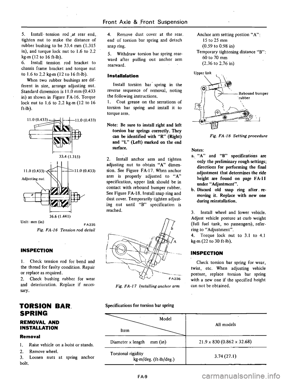
s
Install
tension
rod
at
rear
end
tighten
nut
to
make
the
distance
of
rubber
bushing
to
be
33
4
mm
1
315
in
and
torque
lock
nut
to
1
6
to
2
2
kg
m
12
to
16
ft
lb
6
Install
tension
rod
bracket
to
chassis
frame
bracket
and
torque
nut
to
1
6
to
2
2
kg
m
12
to
16
ft
lb
When
two
rubber
bushings
are
dif
ferent
in
size
arrange
adjusting
nut
Standard
dimension
is
11
0
mOl
0
433
in
as
shown
in
Figure
FA
16
Torque
lock
nut
to
1
6
to
2
2
kg
m
12
to
16
ft
lb
Il
0
11
0
0
433
t
lP
33
4
1
315
I
11
0
0
433
1
0
11
0
0
433
Adjusting
nut
Y
i
w
36
6
l
441
Unit
mm
in
FA235
Fig
FA
16
Tension
rod
detail
INSPECTION
I
Check
tension
rod
for
bend
and
the
thread
for
faulty
condition
Repair
or
replace
as
required
2
Check
bushing
rubber
for
wear
and
deterioration
Replace
if
neces
sary
TORSION
BAR
SPRING
REMOVAL
AND
INSTALLATION
Removal
1
Raise
vehicle
on
a
hoist
or
stands
2
Remove
wheel
3
Loosen
nuts
at
spring
anchor
bolt
Front
Axle
Front
Suspension
4
Remove
dust
cover
at
the
rear
end
of
torsion
bar
spring
and
detach
snap
ring
S
Withdraw
torsion
bar
spring
rear
ward
after
pulling
ou
t
anchor
arm
realWard
I
nstallalation
Install
torsion
bar
spring
in
the
reverse
sequence
of
removal
noting
the
following
instructions
I
Coat
grease
on
the
serrations
of
torsion
bar
spring
and
install
it
to
torque
arm
Note
Be
sure
to
install
right
and
left
torsion
bar
springs
correctly
They
can
be
identified
with
R
Right
and
L
Left
marked
on
the
end
surface
2
Install
anchor
arm
and
tighten
adjusting
nut
to
obtain
A
dimen
sion
See
Figure
F
A
17
When
anchor
arm
is
properly
adjusted
to
A
specification
upper
link
should
be
in
contact
with
rebound
bumper
rubber
See
Figure
FA
18
Install
snap
ring
and
dust
cover
Temporarily
tighten
adjust
ing
nut
until
B
specification
is
reached
I
I
I
FA236
Fig
FA
17
Installing
anchor
arm
Specifications
for
torsion
bar
spring
Diameter
x
length
mOl
in
Torsional
rigidity
kg
m
deg
ft
lb
deg
FA
9
Anchor
arm
setting
post
ion
A
ISt02Smm
0
59
to
0
98
in
Temporary
tightening
distance
B
60
to
70
mOl
2
36
to
2
76
in
UjPPje
Rebound
bumper
rubber
j
4W
Fig
FA
18
Setting
procedure
Notes
3
A
and
8
specifications
are
only
the
preliminary
rough
settings
directions
for
performing
the
final
adjustment
that
determines
the
ride
height
are
found
on
page
F
A
II
under
Adjustment
b
Discard
old
snap
ring
after
re
moving
it
Replace
with
new
one
during
reinstallation
3
Install
wheel
and
lower
vehicle
Adjust
vehicle
posture
at
curb
weight
full
fuel
tank
no
passengers
refer
ring
to
Adjustment
4
Torque
lock
nut
to
3
1
to
4
1
kg
m
22
to
30
ft
lb
INSPECTION
Check
torsion
bar
spring
for
wear
twist
etc
When
adjusting
vehicle
posture
replace
torsion
bar
spring
with
a
new
one
if
the
specified
height
can
not
be
obtained
All
models
21
9
x
830
0
862
x
32
68
3
74
27
I
Page 360 of 537
Note
When
installing
fulcrum
pin
insert
it
from
rearward
of
vehicle
12
Install
tension
rod
shock
ab
sorber
I
stabilizer
torsion
bar
spring
and
knuckle
arm
referring
to
the
related
paragraphs
13
Install
brake
disc
to
knuckle
spindle
and
torque
securing
bolt
to
4
2
to
5
0
kg
m
30
to
36
ft
Ib
14
Install
wheel
and
brake
drum
as
an
assembly
and
torque
knuckle
spin
dle
nut
to
8
0
to
9
0
kg
m
58
to
65
ft
Ib
DISASSEMBLY
AND
ASSEMBLY
Upper
link
I
Detach
upper
link
spindle
from
upper
links
and
remove
clamp
dust
cover
and
dust
seal
Secure
upper
link
in
a
vise
and
loosen
screw
bushing
Assemble
link
spindle
in
reverse
sequence
to
disassembling
noting
the
following
instructions
2
Torque
screw
bushing
on
upper
link
to
3S
to
55
kg
m
253
to
398
ft
Ib
Install
new
dust
seal
and
dust
cover
and
secure
them
with
clamp
3
Coat
grease
to
screw
bushing
in
side
and
the
thread
portion
of
upper
link
spindle
liberally
Screw
front
and
rear
links
to
upper
link
spindle
in
the
same
length
so
as
to
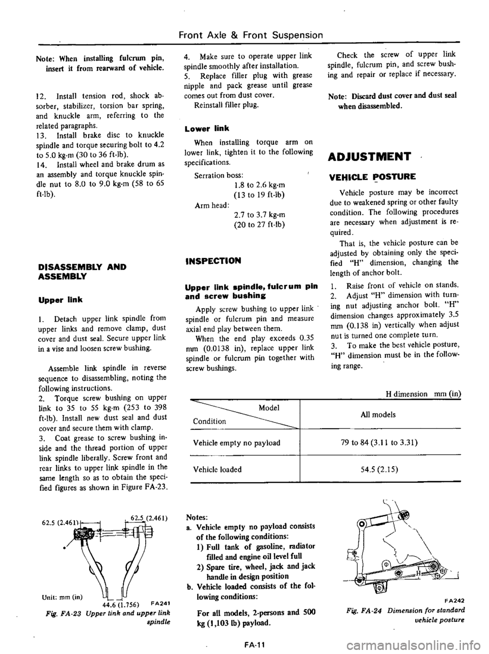
obtain
the
speci
fied
figures
as
shown
in
Figure
FA
23
Unit
mm
in
I
44
6
1
156
FA2
Upper
link
and
upper
link
spindle
Fig
FA
23
Front
Axle
Front
Suspension
4
Make
sure
to
operate
upper
link
spindle
smoothly
after
installation
5
Replace
filler
plug
with
grease
nipple
and
pack
grease
until
grease
comes
out
from
dust
cover
Reinstall
f1ller
plug
Lower
link
When
installing
torque
arm
on
lower
link
tighten
it
to
the
following
specifications
Serration
boss
1
8
to
2
6
kg
m
13
to
19
ft
Ib
Arm
head
2
7
to
3
7
kg
m
20
to
27
ft
tb
INSPECTION
Upper
link
spindle
fulcrum
pin
and
screw
bushing
Apply
screw
bushing
to
upper
link
spindle
or
fulcrum
pin
and
measure
axial
end
play
between
them
When
the
end
play
exceeds
0
35
mm
0
0138
in
replace
upper
link
spindle
or
fulcrum
pin
together
with
screw
bushings
Condition
Vehicle
empty
no
payload
Vehicle
loaded
Notes
a
Vehicle
empty
no
payload
consists
of
the
following
conditions
I
Full
tank
of
gasoline
radiator
f1lled
and
engine
oil
level
full
2
Spare
tire
wheel
jack
and
jack
handle
in
design
position
b
Vehicle
loaded
consists
of
the
fol
lowing
conditions
For
all
models
2
persons
and
SIlO
leg
I
103lb
payload
FA
Check
the
screw
of
upper
link
spindle
fulcrum
pin
and
screw
bush
ing
and
repair
or
replace
if
necessary
Note
Discard
dust
cover
and
dust
seal
when
disassembled
ADJUSTMENT
VEHICLE
POSTURE
Vehicle
posture
may
be
incorrect
due
to
weakened
spring
or
other
faulty
condition
The
following
procedures
are
necessary
when
adjustment
is
Ie
quired
That
is
the
vehicle
posture
can
be
adjusted
by
obtaining
only
the
speci
fied
H
dimension
changing
the
length
of
anchor
bolt
I
Raise
front
of
vehicle
on
stands
2
Adjust
H
dimension
with
turn
ing
nut
adjusting
anchor
bolt
H
dimension
changes
approximately
3
5
mm
0
J38
in
vertically
when
adjust
nut
is
turned
one
complete
turn
3
To
make
the
best
vehicle
posture
H
dimension
must
be
in
the
follow
ing
range
H
dimension
mOl
in
All
models
79
to
84
3
11
to
3
31
54
5
2
15
o
i
Fig
FA
24
FA242
Dimension
for
standard
vehicle
postl4re