check DATSUN PICK-UP 1977 Service Manual
[x] Cancel search | Manufacturer: DATSUN, Model Year: 1977, Model line: PICK-UP, Model: DATSUN PICK-UP 1977Pages: 537, PDF Size: 35.48 MB
Page 316 of 537

CHECKING
SPEED
CHANGING
CONDITION
The
driver
s
feeling
during
gear
changes
should
also
be
checkedatten
tively
I
A
sharp
shock
or
unSffioothness
is
felt
during
a
gear
change
2
A
gear
change
is
made
with
a
long
and
dragging
feeling
These
indicate
that
the
tIuottle
pressure
is
too
low
or
some
valve
connected
to
the
throttle
is
faulty
h
k
100
1
1
2
I
2
J
I
1
2
I
I
I
2
3
oo
I
c
I
E
I
I
300
I
Z
5
L
mmHg
t
1
400
I
I
1
Output
shaft
speed
rpm
20
30
40
50
60
70
80
90100
00
io
3
0
40
0
60
Vehicle
speed
R
4
315
r
0
321
6
00
14
ATll0
Fig
AT
111
Shift
IChedule
Automatic
Transmission
SHI
SCHEDULE
500
CHECKING
ITEMS
DURING
km
hO
1O
SPEED
CHANGE
I
In
D
range
gear
changes
DI
D2
D3
are
effected
In
R
range
the
speed
does
not
increase
2
The
kickdown
operates
properly
3
By
moving
the
lever
from
D
to
I
gear
changes
D
2
1
2
1
are
effected
In
the
ranges
12
and
I
the
engine
braking
works
prop
erly
4
In
I
the
speed
does
not
in
crease
5
Should
be
quickly
fixed
at
2
range
6
In
P
vehicle
can
he
parked
properly
If
any
malfunction
occurs
in
second
gear
during
the
road
test
that
is
if
vehicle
shakes
drags
or
slings
while
shifting
up
from
D
directly
to
D
or
in
shifting
up
from
D
to
D2
the
brake
band
should
be
ad
justed
If
these
troubles
remain
after
the
brake
band
is
adjusted
check
the
servo
piston
seal
for
oil
leakage
MPH
Ii
io
LINE
PRESSURE
TEST
When
any
slipping
occurs
in
clutch
or
brake
or
the
feeling
during
a
speed
change
is
not
correct
the
line
pressure
must
be
checked
Measuring
line
pressure
is
done
by
a
pressure
gauge
attached
to
two
pres
sure
measuring
holes
after
removing
blind
plugs
located
at
transmission
case
See
Figure
AT
112
The
line
pressure
measurement
is
begun
at
idling
and
taken
step
by
step
by
enlarging
the
throttle
opening
I
A
sharp
shock
in
up
shifting
or
too
high
changing
speeds
are
caused
mostly
by
too
high
throttle
pressure
2
Slipping
or
incapability
of
opera
tion
is
mostly
due
to
oil
pressure
leakage
within
the
gear
trains
or
spool
valve
AT
S2
3
3SA
000
t
I
1
I
c
l
1
c
7
D
jf
o
CV
ATl13
1
Lige
pressure
2
Governor
feed
3
SerVo
release
pressure
Fig
AT
112
MeCJ
uring
line
preuure
Page 317 of 537
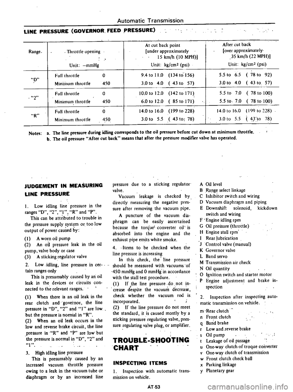
Automatic
Transmission
LINE
PRESSURE
GOVERNOR
FEED
PRESSURE
At
cut
back
point
After
cut
back
Throttle
opening
under
approximately
over
approximately
15
kmfh
10
MPH
35
kmfh
22
MPH
Unit
mmHg
Unit
kgfcm2
psi
Unit
kgfcm2
psi
Full
throtlle
0
9
4
to
11
0
134
to
156
5
5
to
6
5
78
to
92
Minill1um
throttle
450
3
0
to
4
0
43to
57
3
0
to
4
0
43
to
57
Fulllhrotlle
0
10
0
to
12
0
142
to
171
5
5
to
7
0
78
to
100
Minimum
throttle
450
6
0
to
12
0
85to171
5
5
to
7
0
78
to
100
Full
throtlle
0
14
0
to
16
0
199
to
228
14
0
to
16
0
199
to
228
Minimum
throttle
450
3
0
to
5
5
43
to
78
3
0
to
5
5
4
lo
78
Range
D
2
R
Notes
a
The
line
pressure
during
idling
corresponds
to
the
oil
pressure
before
cut
down
at
minimum
throttle
b
The
oil
pressure
After
cut
back
means
that
after
the
pressure
modifier
valve
has
operated
JUDGEMENT
IN
MEASURING
LINE
PRESSURE
Low
idling
line
pressure
in
the
ranges
D
2
I
R
and
pH
This
can
be
atlributed
to
trouble
in
the
pressure
supply
system
or
too
low
output
of
power
caused
by
I
A
worn
oil
pump
2
An
oil
pressure
leak
in
the
oil
pump
valve
body
or
case
3
A
sticking
regulator
valve
2
Low
idling
line
pressure
in
cer
tain
ranges
only
This
is
presumably
caused
by
an
oil
leak
in
the
devices
or
circuits
con
nected
to
the
relevant
ranges
I
When
there
is
an
oil
leak
in
the
rear
clutch
and
governor
the
line
pressure
in
D
2
and
I
are
low
but
the
pressure
is
norrrial
in
R
2
When
an
oil
leak
occurs
in
the
low
and
reverse
brake
circuit
the
line
pressure
in
R
and
P
are
low
but
the
pressure
is
normal
in
D
2
and
I
3
High
idling
line
pressure
This
is
presumably
caused
by
an
increased
vacuum
throttle
pressure
owing
to
a
leak
in
the
vacuum
tube
or
dia
phragm
or
by
an
increased
line
pressure
due
to
a
sticking
regulator
valve
Vacuum
leakage
is
checked
by
directly
measuring
the
negative
pres
sure
after
removing
the
vacuum
pipe
A
puncture
of
the
vacuum
dia
phragm
can
be
easily
ascertained
because
the
torque
converter
oil
is
absorbed
into
the
engine
and
the
exhaust
pipe
emits
white
smoke
4
Items
to
be
checked
when
the
line
pressure
is
increasing
In
this
check
the
line
pressure
should
be
measured
with
vacuums
of
450
mmHg
and
0
mmHg
in
accordance
with
the
stall
test
procedure
I
If
the
line
pressure
do
not
n
crease
despite
the
vacuum
decrease
check
whether
the
vacuum
rod
is
incorporated
2
If
the
line
pressure
do
not
meet
the
standard
it
is
caused
mostly
by
a
sticking
pressure
regulating
valve
pres
sure
regulating
valve
plug
or
amplifier
TROUBLE
SHOOTING
CHART
INSPECTING
ITEMS
1
Inspection
with
automatic
trans
mission
on
vehicle
AT
53
A
Oil
level
B
Ra
lge
select
linkage
C
Inhibitor
switch
and
wiring
D
Vacuum
diaphragm
and
piping
E
Downshift
solenoid
kickdown
switch
and
wiring
F
Engine
idling
rpm
G
Oil
pressure
throttle
H
Engine
stall
rpm
I
Rear
lubrication
J
Control
valve
manual
K
Governor
valve
L
Band
servo
M
Transmission
air
check
N
Oil
quantity
o
Ignition
switch
and
starter
motor
P
Engine
adjustment
and
brake
in
spection
2
Inspection
after
inspecting
auto
matic
transmission
on
vehicle
m
Rear
clutch
n
Front
clutch
q
Band
brake
r
Low
and
reverse
brake
s
Oil
pump
t
Leakage
of
oil
passage
u
One
way
clutch
of
troque
coilVerter
v
One
way
clutch
of
transmission
w
Front
clutch
check
ball
x
Parking
linkage
y
Planetary
gear
Page 318 of 537

Automatic
Transmission
TROUBLE
SHOOTING
CHART
FOR
3N718
AUTOMATIC
TRANSMISSION
The
number
shown
beluw
indicates
the
sequence
in
which
the
checks
should
be
taken
up
Trouble
ABeD
EFGHIIJKL
MNOP
tnnqr
stuv
wxy
ngine
does
not
start
in
N
P
ranges
2
3
1
Engine
starts
in
other
range
than
N
and
P
1
2
Sharp
shock
in
shifting
from
N
to
0
range
Vehicle
will
not
run
in
D
range
bul
I
TUns
in
2u
l
and
R
ranges
2
4
@
3
5
6
3
7
@
@
2
1
3
Vehicle
will
not
run
in
0
1
2
ranges
bul
runs
in
R
range
1
2
Clutch
slips
Very
poor
acceleration
4
Vehicle
will
nol
run
in
R
range
bul
runs
in
0
2
and
I
r
nges
1
2
Iukh
slips
Very
poor
acceleration
3
5
6
4
@@
1
@
@
Vehicle
will
not
run
in
any
range
1
2
3
5
6
4
1
@
@
Clutches
or
brakes
slip
somewhat
1
2
6
I
3
5
7
4
@@
in
starting
Vehicle
runs
in
N
range
I
3
2
Maximum
speed
not
allained
1
2
4
5
7
6
3
8
OO
I@
Acceleration
poor
Vehicle
braked
by
Ihrowing
Icver
inlo
3
2
1
@
I
@
R
range
I
Excessive
creep
1
No
creep
al
all
I
2
3
5
4
@@
@
1
Failure
10
dumge
gear
from
2nd
I
2
3
5
6
8
7
4
@
@
to
3rd
Failure
tllchJllgC
gear
from
1
1
1
2
3
5
6
8
7
4
@
@
@
to
2ud
Too
high
a
gear
change
poinl
from
I
sC
to
2nd
from
2nd
to
1
2
3
5
6
4
1
3rd
Gear
change
directly
from
lsl
to
2
4
3
1
@
@
rd
occurs
AT
54
Page 321 of 537

Automatic
Transmission
TROUBLE
SHOOTING
GUIDE
FOR
3N71B
AUTOMATIC
TRANSMISSION
Order
Test
item
Checking
Oil
level
gauge
2
Downshift
solenoid
3
Manuallinkage
L
4
Inhibitor
switch
5
Engine
idling
rpm
6
Vacuum
pressure
of
vacuum
pipe
7
Operation
in
each
range
8
Creep
of
vehicle
Stall
test
I
Oil
pressure
before
tesling
1
2
Stall
test
3
Oil
pressure
after
testing
Road
test
Slow
acceleration
I
st
2nd
2nd
3rd
2
Quick
acceleration
lst
2nd
2nd
3rd
3
Kick
down
operation
3rd
2nd
or
2nd
1st
Procedure
Check
gauge
for
oil
level
and
leakage
before
and
after
each
test
Check
for
sound
of
operating
solenoid
when
depressing
accelerator
pedal
fully
with
ignition
key
ON
Check
by
shifting
into
P
lR
IN
D
2
and
I
ranges
with
selector
lever
Check
whether
starter
operates
in
N
and
p
ranges
only
and
whether
reverse
lamp
operates
in
R
range
only
Check
whelher
idling
rpm
meet
standard
Check
whether
vacuum
pressure
is
more
than
450
mmHg
in
idling
and
whether
it
decreases
with
increasing
rpm
Check
whether
transmission
engages
positively
by
shifting
N
0
N
2
N
l
I
and
N
R
range
while
idling
with
brake
applied
Check
whether
there
is
any
creep
in
D
2
R
ranges
and
Measure
line
pressures
in
D
2
I
and
R
range
while
idling
Measure
engine
rpm
and
line
pressure
in
D
2
I
and
R
ranges
during
full
throttle
operati
n
Notes
a
Temperature
of
torque
converter
oil
used
in
test
should
be
from
600
to
1000C
1400
to
2120F
i
e
sufficiently
warmed
up
but
not
overheated
b
To
cool
oil
between
each
stall
test
for
D
2
I
and
R
ranges
idle
engine
i
e
rpm
at
about
1
200
rpm
for
more
than
1
minute
in
P
range
Measurement
time
must
not
be
more
than
5
seconds
Same
as
item
I
Check
vehide
speeds
and
engine
cpm
in
shifting
up
Ist
2nd
range
and
2nd
Jo3rd
range
while
running
with
lever
in
D
range
and
engine
vacuum
pressure
of
about
200
I11I1lHg
Same
as
item
1
above
except
with
engine
vacuum
pressure
of
0
mmHg
i
e
in
position
just
before
kickdown
Check
whether
the
kickdown
operates
and
measure
the
time
delays
while
running
at
30
40
50
60
70
km
h
18
25
30
37
43
MPH
in
D3
range
AT
57
Page 322 of 537
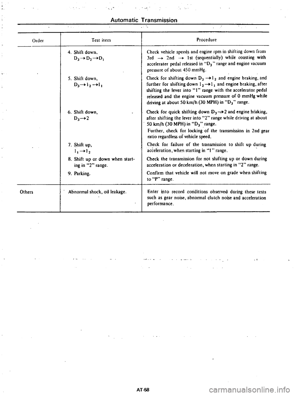
Automatic
Transmission
Order
Test
item
4
Shift
down
Dr
O2
0
5
Shift
down
DJ
12
1
6
Shift
down
DJ
2
7
Shift
up
I
12
8
Shift
up
or
down
when
start
iog
in
2
range
9
Parking
Others
Abnormal
shock
oil
leakage
Procedure
Check
vehicle
speeds
and
engine
rpm
in
shifting
down
from
3rd
2nd
I
st
sequentially
while
coasting
with
accelerater
pedal
released
in
D3
range
and
engine
vacuum
pressure
of
about
450
mmHg
Check
for
shifting
down
OJ
12
and
engine
braking
and
further
for
shifting
down
12
I
and
engine
braking
after
shifting
the
lever
into
I
range
with
the
accelerator
pedal
released
and
the
engine
vacuum
pressure
of
0
mmHg
while
driving
at
about
50
km
h
30
MPH
in
OJ
range
Check
for
quick
shifting
down
0
2
and
engine
biaking
after
shifting
the
lever
into
2
range
while
driving
at
about
50
km
h
30
MPH
in
OJ
range
Further
check
for
locking
of
the
transmission
in
2nd
gear
ratio
regardless
of
vehicle
speed
Check
for
failure
of
the
transmission
to
shift
up
during
acceleration
when
starting
in
I
range
Check
the
transmission
for
not
shifting
up
or
down
during
acceleration
or
deceleration
when
starting
in
2
rang
Confirm
that
vehicle
will
not
move
on
grade
when
shifting
to
P
range
Enter
into
record
conditions
observed
during
these
tests
such
as
gear
noise
abnormal
clutch
noise
and
acceleration
performance
AT
58
Page 326 of 537
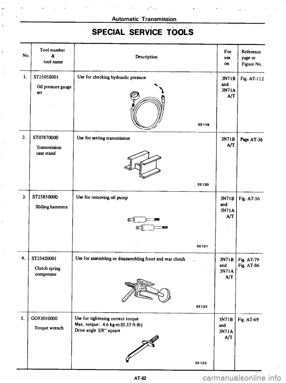
Automatic
Transmission
SPECIAL
SERVICE
TOOLS
No
Tool
number
tool
name
Description
For
use
on
Reference
page
or
Figure
No
Oil
pressure
gauge
set
3N71B
Fig
AT
11
2
and
3N71A
AfT
ST2S0SS001
Use
for
checking
hydraulic
pressure
SE119
2
ST07870000
Use
for
setting
transmission
3N71
B
Page
AT
36
AfT
Transmission
case
stand
SE120
3
ST2S850000
Use
for
removing
oil
pump
3N7IB
Fig
AT
S6
and
Sliding
hammers
3N71A
J
AfT
JIB
SE121
4
ST2S42000I
Use
for
assemblilJg
or
disassembling
front
and
rear
clutch
3N71B
Fig
AT
79
and
Fig
AT
86
Clutch
spring
3N7lA
compressor
AIT
SE
122
3N71B
Fig
AT
69
and
3N71A
AlT
Torque
wrench
Use
for
tightening
correct
torque
Max
torque
4
6
kg
m
0
33
ft
lb
Drive
angle
3
8
square
S
GG93010000
SE123
AT
62
Page 330 of 537
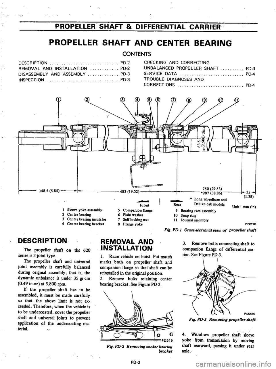
PROPElLER
SHAFT
DIFFERENTIAL
CARRIER
PROPELLER
SHAFT
AND
CENTER
BEARING
CONTENTS
DESCRIPTION
REMOVAL
AND
INSTALLATION
DISASSEMBLY
AND
ASSEMBLY
INSPECTION
i
t
I
tl
J
I
O
148
5
5
85
PD
2
PD
2
PD
3
PD
3
CHECKING
AND
CORRECTING
UNBALANCED
PROPELLER
SHAFT
SERVICE
DATA
TROUBLE
DIAGNOSES
AND
CORRECTIONS
PD
4
PD
3
PD
4
2
483
19
02
750
29
53
987
38
86
Long
wheelbase
and
Deluxe
cab
models
Unit
mm
in
35
1
38
Front
5
Companion
flange
6
Plain
washer
7
Self
locking
nut
8
Flange
yoke
Rea
1
Sleeve
yoke
assembly
2
Center
bearing
3
Center
bearing
insulator
4
Center
bearing
bracket
DESCRIP
TION
The
propeller
shaft
on
the
620
series
is
3
joint
type
The
propeller
shaft
and
universal
joint
assembly
is
carefully
balanced
during
original
assembly
that
is
the
dynamic
unbalance
is
under
35
gr
cm
0
49
in
oz
at
S
800
rpm
If
the
propeller
shaft
has
to
be
assembled
it
must
be
made
carefully
so
that
the
above
limit
is
not
ex
ceeded
Therefore
when
the
vehicle
is
to
be
undercoated
cover
the
propeller
shaft
and
universal
joints
to
prevent
application
of
the
undercoating
ma
terial
9
Bearing
race
assembly
10
Snap
ring
11
Journal
assembly
PD218
Fig
PD
l
Crou
ctional
v
w
of
propelkr
hafl
REMOVAL
AND
INSTALLATION
3
Remove
bolts
connecting
shaft
to
companion
flange
of
differential
car
rier
See
Figure
PD
3
I
Raise
vehicle
on
hoist
Put
match
marks
both
on
propeller
shaft
and
companion
flange
so
that
shaft
can
be
reinstalled
in
the
original
position
2
Remove
bolts
retaining
center
bearing
bracket
See
Figure
PD
2
PD220
Fig
PD
3
Removing
propclkr
cha
t
PD219
Fig
PD
2
Removing
center
bearing
bruckel
4
Withdraw
propeller
shaft
sleeve
yoke
from
transmission
by
moving
shaft
rearward
passing
it
under
rear
axle
PD
2
Page 331 of 537
PROPELLER
SHAFT
DIFFERENTIAL
CARRIER
Watch
for
oil
leakage
from
trans
mission
end
Notes
a
Remove
propeller
shaft
carefully
so
as
not
to
damage
spline
sleeve
yoke
and
rear
oil
seal
b
Plug
up
the
opening
in
the
rear
of
rear
extension
housing
to
prevent
oil
from
flowing
out
To
install
reverse
the
foregoing
removal
procedure
1
Align
propeller
shaft
with
com
panion
flange
using
reference
marks
prescribed
in
removal
procedure
and
assemble
with
bolts
Tightening
torque
2
4
to
3
3
kg
m
17
to
24
ft
Ib
2
Insert
bolts
through
the
holes
of
center
beariug
bracket
and
torque
nuts
to
retain
center
bearing
on
cross
member
Tightening
torque
1
6
to
2
2
kg
m
12
to
16
ft
Ib
DISASSEMBLY
AND
ASSEMBLY
Primarily
do
not
disassemble
pro
peller
shaft
because
it
is
balanced
as
an
assembly
However
check
propeller
shaft
with
journal
for
movement
When
journal
does
not
move
smoothly
dis
assemble
1
Mark
propeller
shaft
and
journal
so
that
the
original
combination
can
be
restored
at
assembly
2
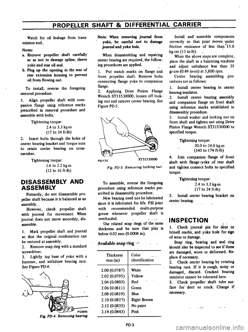
Remove
snap
ring
with
a
standard
screwdriver
3
Lightly
tap
base
of
yoke
with
a
hammer
and
withdraw
bearing
race
See
Figure
PD
4
PDOO5
Fig
PD
4
Remo
i
bearing
Note
When
removing
journal
from
yoke
be
careful
not
to
damage
journal
and
yoke
bole
When
disassembling
and
repairing
center
bearing
are
required
the
follow
ing
procedures
are
applied
1
Put
match
marks
on
flange
and
front
propeller
shaft
Remove
bolts
connecting
flange
yoke
to
companion
flange
2
Applying
Drive
Pinion
Flange
Wrench
ST3lS30000
loosen
off
lock
ing
nut
and
remove
center
bearing
See
Figure
PD
5
P0172
ST31530000
Fig
PD
5
Remouing
locking
nut
To
assemble
reverse
the
foregoing
procedure
using
reference
marks
pre
scribed
in
disassembly
procedure
New
bearing
need
not
be
lubricated
since
it
is
lubricated
for
life
Fill
joint
with
recommended
multi
purpose
grease
whenever
propeller
shaft
is
overhauled
Use
related
snap
rings
of
the
same
thickness
and
be
sure
that
play
is
below
0
02
mm
0
0008
in
Available
snap
ring
Thickness
mm
in
Color
identification
2
00
0
0787
2
02
0
079S
2
Q4
0
0803
2
06
0
08
II
2
08
0
0819
2
10
0
0827
2
12
0
83S
2
14
0
0843
White
Yellow
Red
Green
Blue
Right
Brown
No
paint
Pink
PD
3
Install
and
assemble
components
correctly
so
that
joint
moves
under
friction
resistance
of
less
than
is
o
kg
em
13
in
lb
When
the
above
steps
are
complete
place
the
shaft
in
a
balancing
machine
and
adjust
unbalance
less
than
3S
gr
cm
0
49
in
oz
at
S
800
rpm
Center
bearing
assembling
pro
cedures
are
as
follows
I
Install
center
bearing
in
center
bearing
insulator
2
Install
center
bearing
assembly
and
companion
flange
on
front
shaft
usiug
reference
marks
established
in
disassembly
procedure
3
Install
washer
and
locking
nut
on
front
shaft
and
tighten
nut
using
Drive
Pinion
Flange
Wrench
ST3IS30000
to
specified
torque
Tightening
torque
20
0
to
24
0
kg
m
I4S
to
174
ft
lb
4
Join
companion
flange
of
front
shaft
with
f1ange
yoke
of
rear
shaft
and
tighten
connect
bolts
to
specified
torque
Tightening
torque
2
4
to
3
3
kg
m
17
to
24
ft
Ib
S
Install
center
bearing
bracket
on
center
bearing
INSPECTION
I
Check
journal
pin
for
dent
or
brinell
marks
and
yoke
hole
for
sign
of
wear
or
damage
Snap
ring
bearing
and
seal
ring
should
also
be
inspected
to
see
if
these
are
damaged
worn
or
deformed
Re
place
if
necessary
2
heck
center
bearing
by
rotating
bearing
race
If
it
is
rough
noisy
or
damaged
discard
Cracked
bearing
insulator
cannot
be
tolerated
here
3
Check
propeller
shaft
tube
sur
face
for
dent
or
crack
Change
if
necessary
Page 332 of 537
PROPELLER
SHAFT
8l
DIFFERENTIALCAAR
ER
CHECKING
AND
CQRRECTING
UNBALANCED
PROPELLER
SHAFT
anced
propeller
shaft
proceed
as
follows
I
Remove
undercoating
and
other
foreign
materials
which
could
upset
shaft
balance
and
check
shaft
vibra
tion
by
road
test
2
If
shaft
vibration
is
noted
during
To
check
and
correct
an
unbal
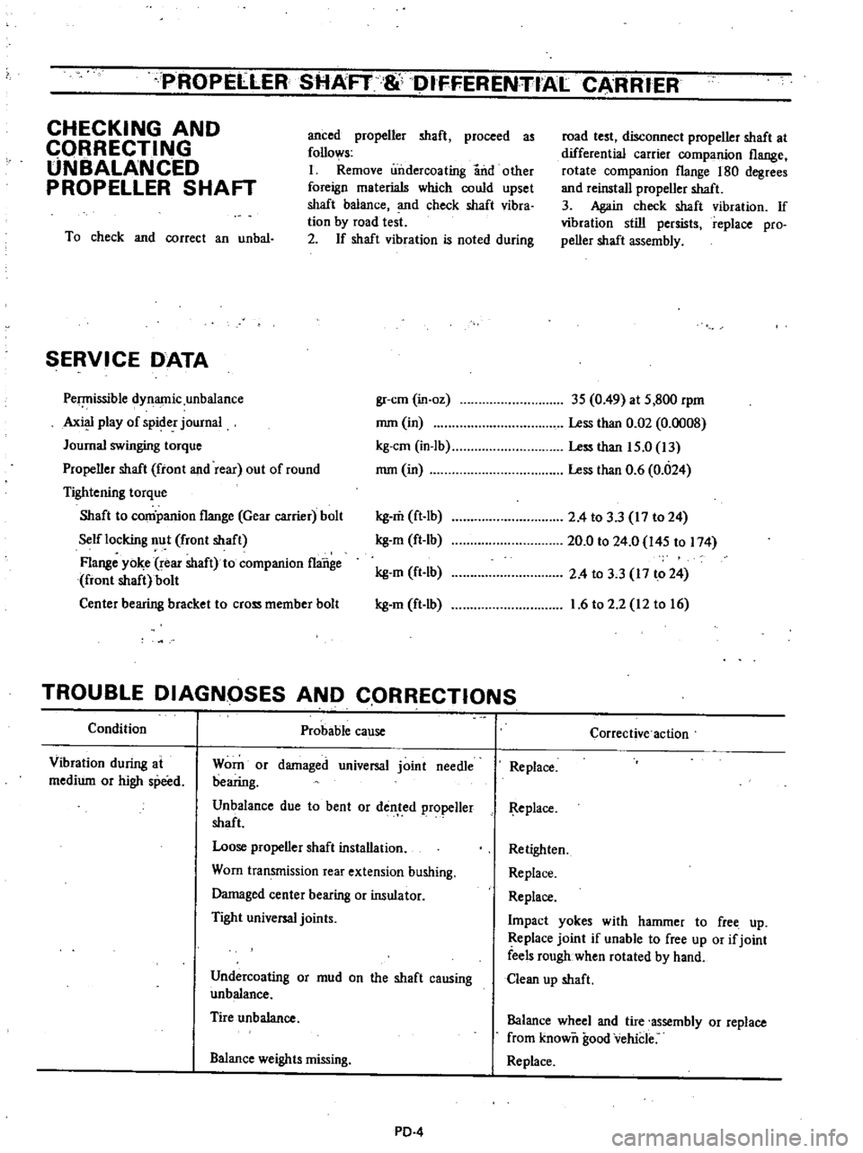
SERVICE
DATA
Pe
issible
dynamic
unbalance
Axi
play
of
spider
journal
Journal
swinging
torque
Propeller
shaft
front
and
rear
out
of
round
Tightening
torque
Shaft
to
conipanion
flange
Gear
carrier
bolt
Self
locking
nut
front
shaft
Flange
yo
e
rear
shaft
to
companion
flange
front
shaft
bolt
Center
bearing
bracket
to
cross
member
bolt
road
test
disconnect
propeller
shaft
at
differential
carrier
companion
flange
rotate
companion
flange
180
degrees
and
reinstall
propeller
shaft
3
Again
check
shaft
vibration
If
vibration
still
persists
replace
pro
peller
shaft
assembly
gr
cm
in
oz
3S
0
49
at
S
800
rpm
mm
in
Less
than
0
02
0
0008
kg
em
in
Ib
Less
than
IS
O
13
mm
in
Less
than
0
6
0
024
kg
m
ft
lb
kg
m
ft
Ib
kg
m
ft
lb
kg
m
ft
lb
2
4
to
3
3
17
to
24
20
0
to
24
0
l4S
to
174
2
4
to
3
3
17
to
24
1
6
to
2
2
12
to
16
TROUBLE
DIAGNOSES
AND
CQRRECTIONS
Condition
Probable
cause
Vibration
during
at
medium
or
high
speed
Worn
or
damaged
universal
joint
needle
bearing
Unbalance
due
to
bent
or
dented
propeller
shaft
Loose
propeller
shaft
installation
Worn
transmission
rear
extension
bushing
Damaged
center
bearing
or
insulator
Tight
universal
joints
Undercoating
or
mud
on
the
shaft
causing
unbalance
Tire
unbalance
Balance
weights
missing
PD
4
Corrective
action
Replace
I
l
eplace
Retighten
Replace
Replace
Impact
yokes
with
hammer
to
free
up
Replace
joint
if
unable
to
free
up
or
if
joint
feels
rough
when
rotated
by
hand
Clean
up
shaft
Balance
wheel
and
tire
assembly
or
replace
from
known
good
vehicle
Replace
Page 335 of 537
PROPELLER
SHAFT
DIFFERENTIAL
CARRIER
REMOVAL
I
Jack
up
rear
of
vehicle
and
sup
port
it
by
placing
a
safety
stand
under
rear
axle
case
Drain
gear
oil
2
Remove
propeller
shaft
and
rear
axle
shafts
These
works
can
be
done
by
referring
to
Rear
Axle
and
Rear
Suspension
3
Loosen
off
bolts
securing
differ
ential
carrier
to
rear
axle
cas
and
take
out
differential
carrier
assembly
PRE
DISASSEMBLY
INSPECTION
Differential
carrier
should
be
in
spected
before
any
parts
are
removed
from
it
These
inspections
are
helpful
to
fmd
the
cause
of
a
problem
and
to
determine
the
corrections
needed
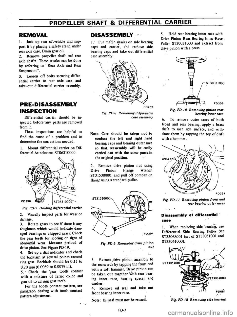
I
Mount
differential
carrier
on
Dif
ferential
Attachment
ST063
I
0000
ST063
10000
Fig
PD
7
Holding
differential
can
ier
2
Visually
inspect
parts
for
wear
or
damage
3
Rotate
gears
to
see
if
there
is
any
roughness
which
would
indicate
dam
aged
bearings
or
chipped
gears
Check
the
gear
teeth
for
scoring
or
signs
of
abnormal
wear
Measure
preload
of
drive
pinion
See
Figure
PD
19
4
Set
up
a
dial
indicator
and
check
the
backlash
at
several
points
around
ring
gear
Backlash
should
be
0
15
to
0
20
mOl
0
00S9
to
0
0079
in
S
Check
the
gear
tooth
contact
with
a
mixture
of
ferric
oxide
and
g
ar
oil
to
all
ring
gear
teeth
For
the
tooth
contact
pattern
see
paragraph
dealing
with
tooth
contact
pattern
adjustment
DISASSEMBLY
I
Put
match
tpark
on
side
bearing
caps
and
carrier
and
remove
side
bearing
caps
and
take
out
differential
case
assembly
P0203
Fig
PD
B
Removing
differenlwl
case
assem
bly
Note
Care
should
be
taken
not
to
confuse
the
left
and
right
hand
bearing
caps
and
bearing
outer
race
so
that
reassembly
will
be
easily
carried
out
with
the
same
parts
in
the
original
position
2
Remove
drive
pinion
nut
using
Drive
Pinion
Flange
Wrench
ST31530000
and
pull
off
companion
flange
using
a
standard
puller
Fig
PD
9
Removing
drive
pinion
nul
3
Extract
drive
pinion
assembly
to
the
rearwards
by
tapping
the
front
end
with
a
soft
hammer
Drive
pinion
can
be
taken
out
together
with
rear
bear
ing
nner
race
bearing
spacer
and
washer
4
Remove
oil
seal
and
take
out
front
bearing
inner
race
Note
Oil
seal
must
not
be
used
PD
7
5
Hold
rear
bearing
inner
race
with
Drive
Pinion
Rear
Bearing
Inner
Race
Puller
ST30031000
and
extract
from
drive
pinion
with
a
press
STJ0031000
PD205
Fig
PD
10
Removing
pinion
rear
bearing
inner
race
6
To
remove
outer
races
of
both
front
and
rear
bearing
apply
a
brass
drift
to
race
side
surface
and
with
draw
them
by
tapping
the
top
of
drift
with
a
hammer
Fig
PD
l1
Removing
pinion
front
and
rear
bearing
outer
races
Dissssembly
of
dHferentIeI
case
1
When
replacing
side
bearing
use
Differential
Side
Bearing
Puller
Set
ST3306S00
I
set
of
ST330S100
I
and
ST33061000
Fig
PD
12
Removing
ide
bearing