engine oil DATSUN PICK-UP 1977 Workshop Manual
[x] Cancel search | Manufacturer: DATSUN, Model Year: 1977, Model line: PICK-UP, Model: DATSUN PICK-UP 1977Pages: 537, PDF Size: 35.48 MB
Page 96 of 537
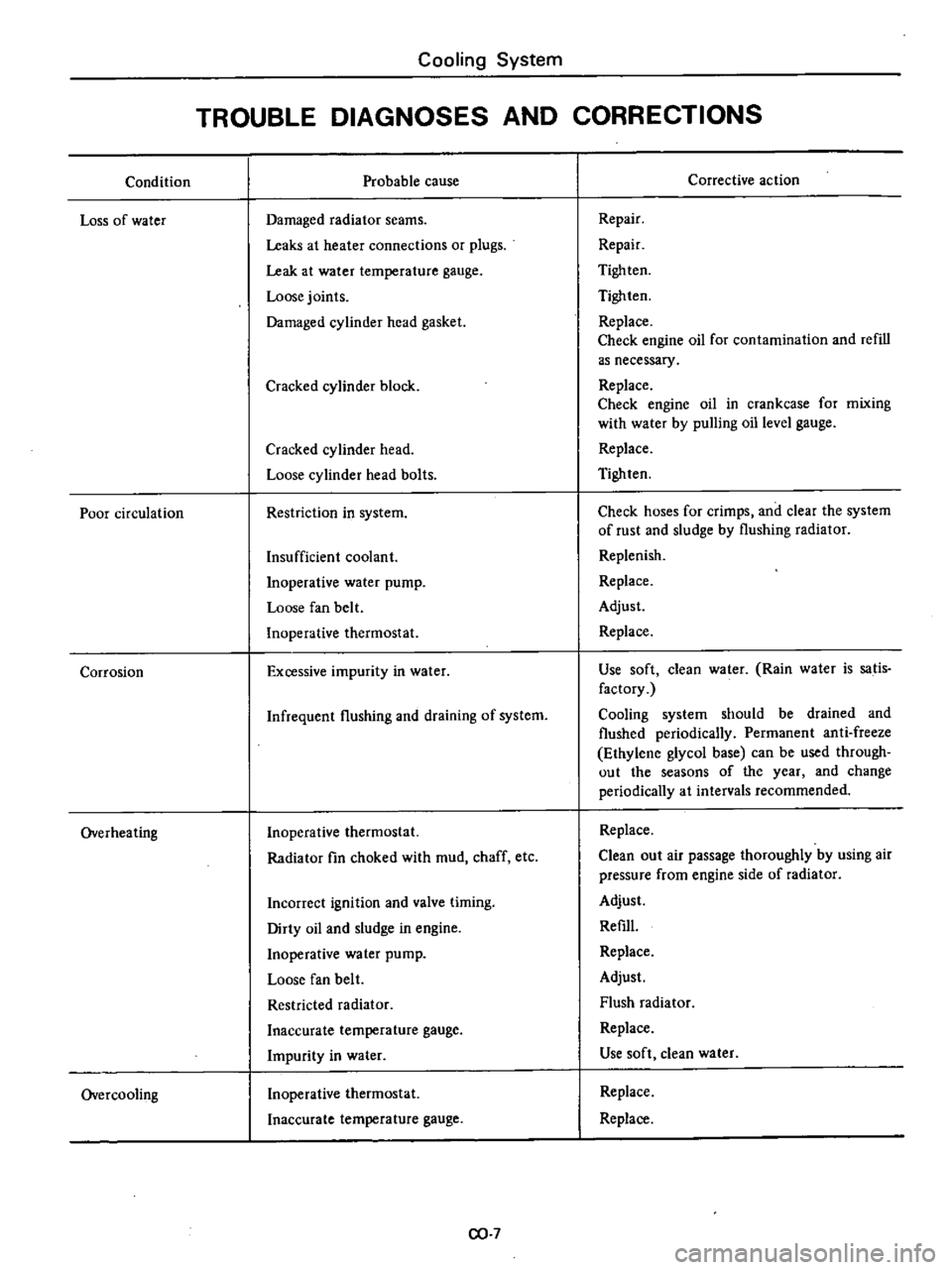
Condition
Loss
of
water
Poor
circulation
Corrosion
Overheating
Overcooling
Cooling
System
TROUBLE
DIAGNOSES
AND
CORRECTIONS
Probable
cause
Damaged
radiator
seams
Leaks
at
heater
connections
or
plugs
Leak
at
water
temperature
gauge
Loose
joints
Damaged
cylinder
head
gasket
Cracked
cylinder
block
Cracked
cylinder
head
Loose
cylinder
head
bolts
Restriction
in
system
Insufficient
coolant
Inoperative
water
pump
Loose
fan
belt
Inoperative
thermostat
Excessive
impurity
in
water
Infrequent
flushing
and
draining
of
system
Inoperative
thermostat
Radiator
fin
choked
with
mud
chaff
etc
Incorrect
ignition
and
valve
timing
Dirty
oil
and
sludge
in
engine
Inoperative
water
pump
Loose
fan
belt
Restricted
radiator
Inaccurate
temperature
gauge
Impurity
in
water
Inoperative
thermostat
Inaccurate
temperature
gauge
CO
7
Corrective
action
Repair
Repair
Tigh
ten
Tighten
Replace
Check
engine
oil
for
contamination
and
refill
as
necessary
Replace
Check
engine
oil
in
crankcase
for
mixing
with
water
by
pulling
oil
level
gauge
Replace
Tighten
Check
hoses
for
crimps
and
clear
the
system
of
rust
and
sludge
by
flushing
radiator
Replenish
Replace
Adjust
Replace
Use
soft
clean
water
Rain
water
is
satis
factory
Cooling
system
should
be
drained
and
flushed
periodically
Permanent
anti
freeze
Ethylene
glycol
base
can
be
used
through
out
the
seasons
of
the
year
and
change
periodically
at
intervals
recommended
Replace
Clean
out
air
passage
thoroughly
by
using
air
pressure
from
engine
side
of
radiator
Adjust
Refill
Replace
Adjust
Flush
radiator
Replace
Use
soft
clean
water
Replace
Replace
Page 98 of 537
Engine
Fuel
AUTOMATIC
TEMPERATURE
CONTROL
A
T
C
AIR
CLEANER
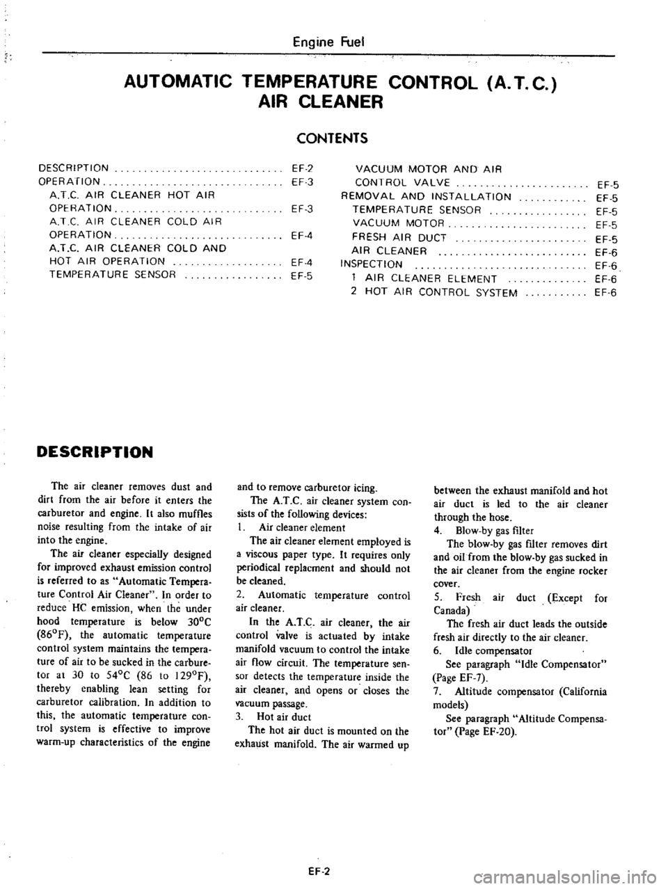
DESCRIPTION
OPERATION
A
T
C
AIR
CLEANER
HOT
AIR
OPERATION
A
T
C
AIR
CLEANER
COLD
AIR
OPERATION
A
T
C
AIR
CLEANER
COLD
AND
HOT
AIR
OPERATION
TEMPERATURE
SENSOR
DESCRIPTION
The
air
cleaner
removes
dust
and
dirt
from
the
air
before
it
enters
the
carburetor
and
engine
It
also
muffles
noise
resulting
from
the
intake
of
air
into
the
engine
The
air
cleaner
especially
designed
for
improved
exhaust
emission
control
is
referred
to
as
Automatic
Tempera
ture
Control
Air
Cleaner
In
order
to
reduce
HC
emission
when
the
under
hood
temperature
is
below
300C
860F
the
automatic
temperature
control
system
maintains
the
tempera
ture
of
air
to
be
sucked
in
the
carbure
tor
at
30
to
540C
86
to
1290F
thereby
enabling
lean
setting
for
carburetor
calibration
n
addition
to
this
the
automatic
temperature
con
twl
system
is
effective
to
improve
warm
up
characteristics
of
the
engine
CONTENTS
EF
2
EF
3
VACUUM
MOTOR
AND
AIR
CONTROL
VALVE
REMOVAL
AND
INSTALLATION
TEMPERATURE
SENSOR
VACUUM
MOTOR
FRESH
AIR
DUCT
AIR
CLEANER
INSPECTION
1
AIR
CLEANER
ELEMENT
2
HOT
AIR
CONTROL
SYSTEM
EF
3
EF
4
EF
4
EF
5
and
to
remove
carburetor
icing
The
A
T
C
air
cleaner
system
con
sists
of
the
following
devices
1
Air
cleaner
element
The
air
cleaner
element
employed
is
a
viscous
paper
type
It
requires
only
periodical
replacment
and
should
not
be
cleaned
2
Automatic
temperature
control
air
cleaner
In
the
A
T
C
air
cleaner
the
air
control
valve
is
actuated
by
intake
manifold
vacuum
to
control
the
intake
air
flow
circuit
The
temperature
sen
sor
detects
the
temperature
inside
the
air
cleaner
and
opens
or
closes
the
vacuum
passage
3
Hot
air
duct
The
hot
air
duct
is
mounted
on
the
exhaust
manifold
The
air
warmed
up
EF
2
EF
5
EF
5
EF
5
EF
5
EF
5
EF
6
EF
6
EF
6
EF
6
between
the
exhaust
manifold
and
hot
air
duct
is
led
to
the
air
cleaner
through
the
hose
4
Blow
by
gas
filter
The
blow
by
gas
nIter
removes
dirt
and
oil
from
the
blow
by
gas
sucked
in
the
air
cleaner
from
the
engine
rocker
cover
5
Fresh
air
duct
Except
for
Canada
The
fresh
air
duct
leads
the
outside
fresh
air
directly
to
the
air
cleaner
6
Idle
compensator
See
paragraph
Idle
Compensator
Page
EF
7
7
Altitude
compensator
California
models
See
paragraph
Altitude
Compensa
tor
Page
EF
20
Page 106 of 537

4
Run
the
engine
at
varying
speeds
5
The
pressure
gauge
indicates
static
fuel
pressure
in
the
line
The
gauge
reading
should
be
within
the
following
range
0
21
to
0
27
kg
em2
3
0
to
3
8
psi
Note
If
the
fuel
in
carburetor
float
chamber
has
run
out
and
engine
has
stopped
clip
and
pour
fuel
into
carburetor
Fasten
clip
secure
ly
and
repe
1
static
pressure
test
Pressure
below
the
lower
limit
indi
cates
extreme
wear
on
one
part
or
a
small
amount
of
wear
on
each
working
part
It
also
indicates
ruptured
dia
phragm
worn
warped
dirty
or
gum
ming
valves
and
seats
or
a
weak
diaphragm
return
spring
Pressure
above
the
upper
limit
indicates
an
excessively
strong
tension
of
dia
phragm
return
spring
or
a
diaphragm
that
is
too
tight
Both
of
these
condi
tions
require
the
removal
of
pump
assembly
for
replacement
or
repair
CAPACITY
TEST
The
capacity
test
is
made
only
when
static
pressure
is
within
the
specifications
To
make
this
test
pro
ceed
as
follows
1
Disconnect
pressure
gauge
from
T
connector
and
in
its
vacant
place
install
a
suitable
container
as
a
fuel
sump
2
Run
engine
at
1
000
rpm
3
The
pump
should
deliver
1
000
cc
2
11
US
pt
of
fuel
in
one
minute
or
less
If
little
or
no
fuel
flows
from
the
open
end
of
pipe
it
is
an
indication
that
fuel
line
is
clogged
or
pump
is
malfunctioning
REMOVAL
AND
DISASSEMBLY
Remove
fuel
pump
assembly
by
unscrewing
two
mounting
nuts
and
disassemble
in
the
following
order
1
Separate
upper
body
and
lower
body
by
unscrewing
body
set
screws
Engine
Fuel
2
Take
off
cap
and
cap
gasket
by
removing
cap
screws
3
Unscrew
elbow
and
connector
4
Take
off
valve
retainer
by
un
screwing
two
retainer
screws
and
re
move
two
valves
5
To
remove
diaphragm
press
down
its
center
against
spring
force
With
diaphragm
pressed
down
tilt
it
until
the
end
of
pull
rod
touches
the
inne
wall
of
body
Then
release
diaphragm
to
unhook
push
rod
Be
careful
during
this
operation
not
to
damage
diaphragm
or
oil
se
L
i
J
EFOO7
Fig
EF
20
Remouing
pull
rod
6
Drive
rocker
arm
pin
out
with
a
press
or
hammer
8
o
6
7
8
@
INSPECTION
I
Check
upper
body
and
lower
body
for
cracks
EF
10
I
fuel
pump
cap
2
Cap
gasket
3
Valve
packing
4
fuel
pump
val
e
assembly
S
Valve
retainer
6
Diaphragm
assembly
7
Diaphragm
spring
8
PuRro
9
Lower
body
seal
washer
10
Lower
body
seal
11
Inkl
connector
12
Outlet
connector
13
Rocker
arm
spring
14
Rocker
arm
I
S
Rocker
artyl
side
pin
16
Fuel
pump
packing
17
Spacer
fuel
pump
fo
cylinder
block
EF510
Fig
EF
21
Slruc
ure
of
fuel
pump
2
Check
valve
assembly
for
wear
on
valve
and
valve
spring
Blow
valve
assembly
with
brea
th
to
examine
its
function
Page 107 of 537
3
Check
diaphragm
for
small
holes
carcks
or
wear
4
Check
rocker
arm
for
wear
at
the
mating
portion
with
camshaft
5
Check
rocker
arm
pin
for
wear
A
worn
pin
may
cause
oil
leakage
6
Check
all
other
components
for
any
abnormalities
and
replace
if
neces
sary
DESCRIPTION
INSPECTION
REMOVAL
AND
INSTALLATION
DESCRIPTION
The
electric
fuel
pump
is
adopted
on
air
conditioner
equipped
models
Engine
Fuel
ASSEMBLY
Reverse
the
order
of
disassembly
Closely
observe
the
following
instruc
tions
L
Use
new
gaskets
2
Lubricate
rocker
ann
rocker
arm
link
and
rocker
arm
pin
before
installa
tion
3
To
test
the
function
proceed
as
follows
Position
fuel
pump
assembly
about
I
meter
3
3
ft
above
fuel
level
of
fuel
strainer
and
connect
a
pipe
from
strainer
to
fuel
pump
Operate
rocker
arm
by
hand
If
fuel
is
drawn
up
soon
after
rocker
arm
is
released
fuel
pump
is
functioning
properly
ELECTRIC
FUEL
PUMP
CONTENTS
EF
11
EF
11
EF
12
DISASSEMBL
Y
ASSEMBL
Y
TROUBLE
DIAGNOSES
AND
CORRECTIONS
EF
12
EF
12
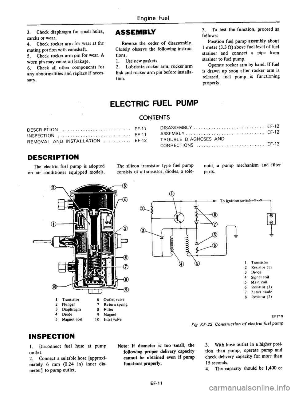
The
silicon
transistor
type
fuel
pump
consists
of
a
transistor
diodes
a
sole
I
Tr
lOsistor
6
Ou
tIet
valve
2
Plunger
7
Return
spring
3
Diaphragm
8
Filter
4
Diode
9
Magnet
5
Magnet
coil
10
Inlet
valve
INSPECTION
I
Disconnect
fuel
hose
at
pump
outlet
2
Connect
a
suitable
hose
approxi
mately
6
mm
0
24
in
inner
dia
meter
to
pump
outlet
ev
J
J
Note
If
diameter
is
too
small
the
following
proper
delivery
capacity
cannot
be
obtained
even
if
pump
functions
properly
EF
11
EF
13
noid
a
pump
mechanism
and
filter
parts
I
T
nsistor
2
Re
ist
f
I
3
Dinde
4
Signal
coil
5
Main
coil
6
Resistor
3
7
Zener
dlOdl
8
Resistor
2
EF719
Fig
EF
22
Construction
of
electric
fuel
pump
3
With
hose
outlet
in
a
higher
posi
tion
than
pump
operate
pump
and
check
delivery
capacity
for
more
than
15
seconds
4
The
capacity
should
be
I
400
cc
Page 135 of 537

There
are
three
types
of
control
system
These
are
J
Closed
type
CIllnkcase
emission
control
system
Emission
Control
System
of
GENERAL
DESCRIPTION
2
Exhaust
emission
control
system
3
Evaporative
ell
lhsion
control
sys
tem
Pericxiic
inspection
and
required
seCV1Clng
of
these
systems
should
be
carried
out
to
reduce
harmful
emis
sions
to
a
minimum
CRANKCASE
EMISSION
CONTROL
SYSTEM
c
01
Lkf
If
1
TIL
II
tll
1
j
GUuuu
DESCRIPTION
This
system
returns
blow
by
gas
to
both
the
intake
manifold
and
carbure
tor
air
cleaner
The
positive
crankcase
ventilation
p
C
V
valve
is
provided
to
conduct
crankcase
blow
by
gas
to
the
intake
manifold
During
partial
throttle
operation
of
the
engine
the
intake
manifold
sucks
the
blow
by
gas
through
the
P
C
V
valve
Normally
the
capacity
of
the
valve
is
sufficient
to
handle
any
blow
by
and
a
small
amount
of
ventilating
air
4
c
Fresh
air
Blow
by
gas
The
ventilating
air
is
then
drawn
from
the
dust
side
of
the
cadlUretor
air
cleaner
tluough
the
tube
con
necting
carburetor
air
cleaner
to
rock
er
cover
into
the
crankcase
Under
full
tluottle
condition
the
manifold
vacuwn
is
insufficient
to
draw
the
blow
by
flow
tluough
the
valve
and
its
flow
goes
through
the
tube
connection
in
the
reverse
diree
tion
On
vehicles
with
an
excessively
high
blow
by
some
of
the
flow
will
go
through
the
tube
connection
to
carbu
retor
air
cleaner
under
all
conditions
1
Sealtypc
oil
level
gauge
2
Bame
plate
3
Flame
arrester
4
Filler
5
P
C
Y
valve
6
Steel
net
7
Bame
plate
EC716
Fig
EC
l
Crankcase
miaion
control
ay
tem
EC
2
INSPECTION
P
c
V
VALVE
AND
FILTER
Checking
P
C
V
valve
in
accord
ance
with
the
following
method
With
engine
running
at
idle
remove
the
ventilator
hose
from
P
C
V
valve
if
the
valve
is
working
a
hissing
noise
will
be
heard
as
air
passes
through
the
valve
and
a
strong
vacuwn
should
be
felt
immediately
when
a
fmger
is
placed
over
valve
inlet
Replace
P
C
V
valve
and
filter
in
accordance
with
the
maintenance
schedule
VENTILATION
HOSE
1
Check
hoses
and
hose
connec
tions
for
leaks
2
Disconnect
all
hoses
and
clean
with
compressed
air
If
any
hose
cannot
be
free
of
obstructions
replace
Ensure
that
flame
arrester
is
surely
inserted
in
hose
between
air
cleaner
and
rocker
cover
Page 139 of 537
Emission
Control
System
EARLY
FUEL
EVAPORATIVE
SYSTEM
E
F
E
DESCRIPTION
spring
and
counterweight
which
are
assembled
on
the
valve
shaft
projecting
to
the
rear
outside
of
the
exhaust
manifold
The
counterweight
is
se
cured
to
the
valve
shaft
with
key
bolt
and
snap
ring
EC
4
A
control
valve
welded
to
the
valve
shaft
is
wtalled
on
the
exhaust
manifold
through
bushing
This
con
trol
valve
is
called
Heat
control
valve
The
heat
control
valve
is
ac
luated
by
the
coil
spring
thermostat
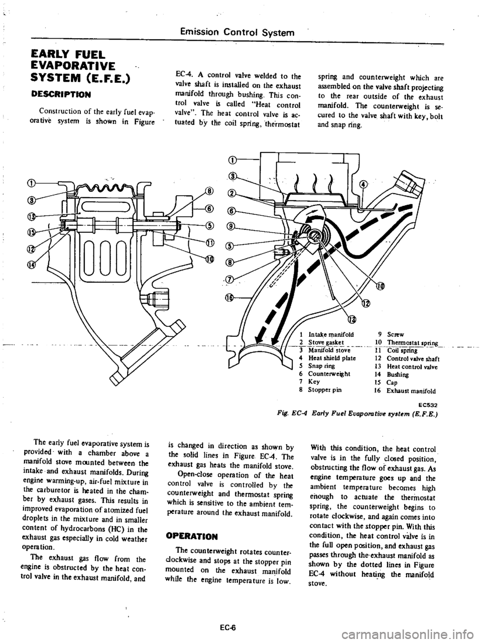
Construction
of
the
early
fuel
evap
orative
system
is
shown
in
Figure
r
I
1
@
rW
9
Sc
w
10
Thennostat
spring
11
Coil
spriiig
12
Control
valve
shaft
13
Heat
control
valve
14
Bushing
15
Cap
16
Exhaust
manifold
1
Intake
manifold
2
Stove
gasket
ManifoktstOve
4
Heat
shield
plate
5
Snap
ring
6
Counterweight
7
Key
g
Stoppel
pin
EC532
Fig
EC
4
Early
Fuel
Evaporutive
tem
E
F
E
The
early
fuel
evaporative
system
is
provided
with
a
chamber
above
a
manifold
stove
moonted
between
the
intake
and
exhaust
manifolds
During
engine
warming
up
air
fuel
mixture
in
the
carburetor
is
heated
in
the
cham
bet
by
exhaust
gases
This
results
in
improved
evaporation
of
atomized
fuel
droplets
in
the
mixture
and
in
smaller
content
of
hydrocarbons
He
in
the
exhaust
gas
especially
in
cold
weather
operation
The
exhaust
gas
flow
from
the
engine
is
obstructed
by
the
heat
con
trol
valve
in
the
exhaust
manifold
and
is
changed
in
direction
as
shown
by
the
solid
lines
in
Figure
EC
4
The
exhaust
gas
heats
the
manifold
stove
Open
close
operation
of
the
heat
control
valve
is
controlled
by
the
counterweight
and
thermostat
spring
which
is
sensitive
to
the
ambient
tem
perature
around
the
exhaust
manifold
With
this
condition
the
heat
control
valve
is
in
the
fully
closed
position
obstructing
the
flow
of
exhaust
gas
As
engine
tempera
lure
goes
up
and
the
ambient
temperature
becomes
high
enough
to
actuate
the
thermostat
spring
the
counterweight
begins
to
rotate
clockwise
and
again
comes
into
con
tact
with
the
stopper
pin
With
this
condition
the
heat
control
valve
is
in
the
full
open
position
and
exhaust
gas
passes
through
the
exhaust
manifold
as
shown
by
the
dotted
lines
in
Figure
EC
4
without
heati
ng
the
manifold
stove
OPERATION
The
counterweight
rotates
counter
clockwise
and
stops
at
the
stopper
pin
mounted
on
the
exhaust
manifold
while
the
engine
temperature
is
low
EC
6
Page 140 of 537
REMOVAL
AND
INSTAUATION
Emission
Control
System
EC533
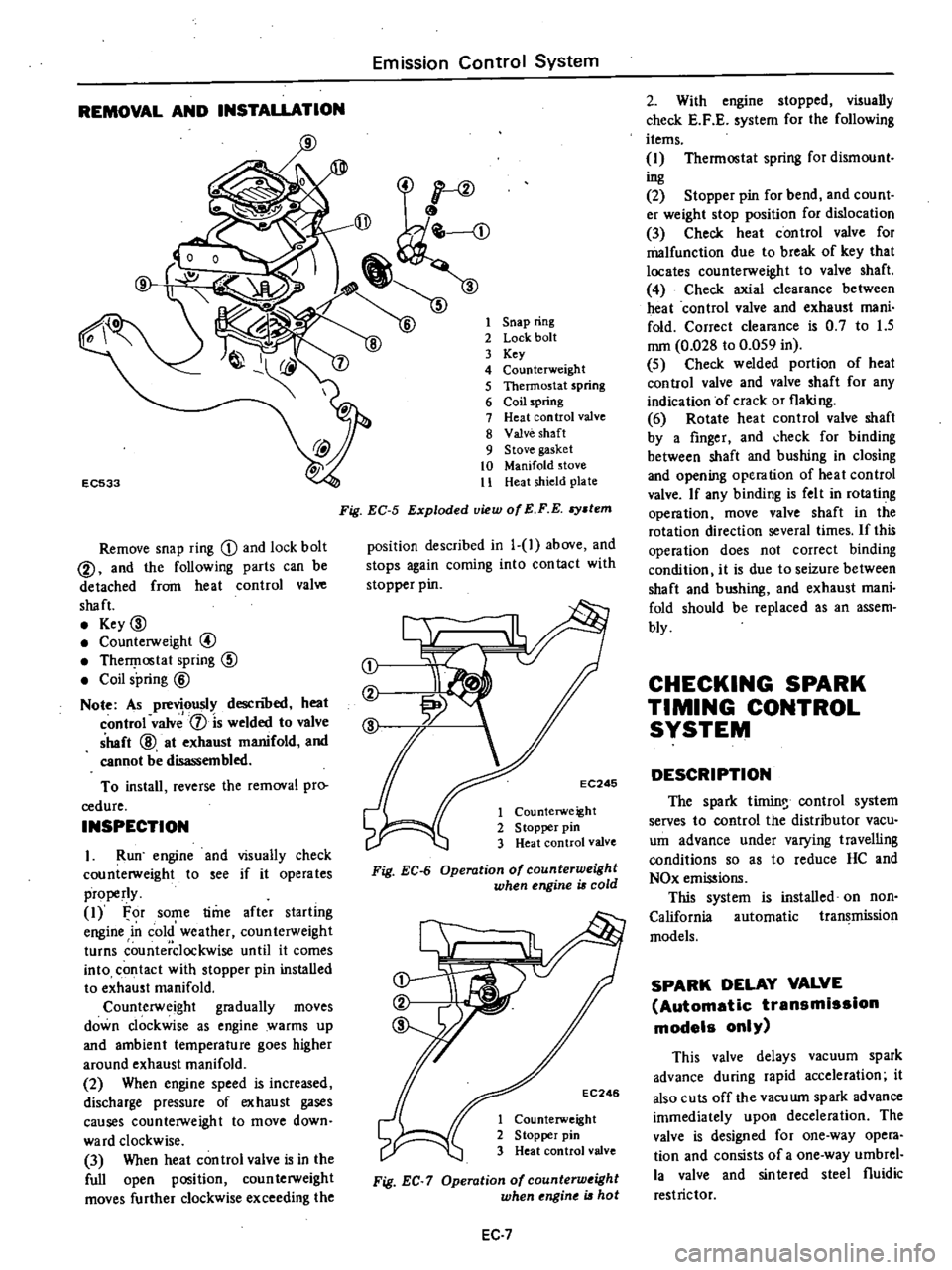
Remove
snap
ring
D
and
lock
bolt
@
and
the
following
parts
can
be
detached
from
heat
control
valve
shaft
Key
00
Counterweight
@
TherI
lostat
spring
CID
Coil
spring
@
Note
As
previously
descnoed
heat
control
valv
1
is
welded
to
valve
shaft
@
at
exhaust
manifold
and
cannot
be
disassembled
To
install
reverse
the
removal
pro
cedure
INSPECTION
I
Run
engine
and
visually
check
counterweight
to
see
if
it
operates
properly
1
For
some
time
after
starling
engine
in
cold
weather
counterweight
turns
counterclockwise
until
it
comes
into
contact
with
stopper
pin
installed
to
exhaust
manifold
Counterweight
gradually
moves
down
clockwise
as
engine
warms
up
and
ambient
temperature
goes
higher
around
exhaust
manifold
2
When
engine
speed
is
increased
discharge
pressure
of
exhaust
gases
causes
counterweight
to
move
down
ward
clockwise
3
When
heat
con
trol
valve
is
in
the
full
open
position
coun
terweight
moves
further
clockwise
exceeding
the
1
Snap
ring
2
Lock
bolt
3
Key
4
Counterweight
5
Thermostat
spring
6
Coil
spring
7
Heat
control
valve
8
Valve
shaft
9
Stove
gasket
10
Manifold
stove
11
Heat
shield
plate
Fig
EC
5
Exploded
view
of
E
F
E
stem
position
described
in
1
1
above
and
stops
again
coming
into
con
tact
with
stopper
pin
j
EC246
1
Counterweight
2
S
topper
pin
3
Heat
control
valve
Fig
EC
6
Operation
of
counterweight
when
engine
is
cold
EC246
1
Counterweight
2
Stopper
pin
3
Heat
control
valve
Fig
EC
7
Operation
of
counterw
ight
when
ngine
is
hot
EC
7
2
With
engine
stopped
visually
check
E
F
E
system
for
the
following
items
1
Thermostat
spring
for
dismount
ing
2
Stopper
pin
for
bend
and
count
er
weight
stop
position
for
dislocation
3
Check
heat
control
valve
for
malfunction
due
to
break
of
key
that
locates
counterweight
to
valve
shaft
4
Check
axial
clearance
between
heat
control
valve
and
exhaust
mani
fold
Correct
clearance
is
0
7
to
1
5
mm
0
028
to
0
059
in
5
Check
welded
portion
of
heat
control
valve
and
valve
shaft
for
any
indication
of
crack
or
flaking
6
Rotate
heat
control
valve
shaft
by
a
finger
and
check
for
binding
between
shaft
and
bushing
in
closing
and
opening
operation
of
heat
control
valve
If
any
binding
is
felt
in
rotating
operation
move
valve
shaft
in
the
rotation
direction
several
times
If
this
operation
does
not
correct
binding
condition
it
is
due
to
seizure
between
shaft
and
bushing
and
exhaust
mani
fold
should
be
replaced
as
an
assem
bly
CHECKING
SPARK
TIMING
CONTROL
SYSTEM
DESCRIPTION
The
spark
tirnin
control
system
serves
to
control
the
distributor
vacu
um
advance
under
varying
travelling
conditions
so
as
to
reduce
HC
and
NOx
emissions
This
system
is
installed
on
non
California
automatic
transmission
models
SPARK
DELAY
VALVE
Automatic
transmission
models
only
This
valve
delays
vacuum
spark
advance
during
rapid
acceleration
it
also
cuts
off
the
vacuwn
spark
advance
immediately
upon
deceleration
The
valve
is
designed
for
one
way
opera
tion
and
consists
of
a
one
way
umbrel
la
valve
and
sinlered
steel
fluidic
restrictor
Page 147 of 537

9
From
air
pump
l
h
1
Not
actuated
REMOVAL
AND
INSTALLATION
Air
p
mp
sir
cleaner
Remove
air
hose
then
detach
air
cleaner
from
hoodledge
Air
cleaner
element
and
Ii
r
deancr
lower
body
are
built
into
a
unit
construction
Replace
air
cleaner
clcl
nen
and
lower
body
as
an
assembly
J
J
tt
c
t
o
J
EC
323
Fig
EC
26
Replacing
oir
cleaner
element
Air
pum
Remove
air
hoses
from
air
pump
2
Loosen
air
pump
adjusting
bar
mounting
bolts
and
air
pump
mount
ing
bolts
then
remove
air
pump
drive
bell
3
Remove
air
pump
pulley
4
Remove
air
pump
from
bracket
Air
control
valve
California
models
l
Disconnect
air
hoses
and
a
vacu
um
hose
from
air
control
valve
2
Remove
air
con
trol
valve
from
bracket
E
A
R
valve
California
modela
Remove
vacuum
pipe
and
air
hose
and
dismount
E
A
R
valve
Emission
Control
System
o
jJ
To
Intake
mamfold
rF
vacuum
r
To
air
cleaner
From
air
pump
EC781
Fig
EC
27
Locotion
of
E
A
R
wive
Antl
backflravalve
Disconnect
air
hose
and
vacuum
hose
from
anti
backfire
valve
Check
valve
Disconnect
hose
and
remove
check
valve
from
air
gallery
pipe
Air
ganery
pIpe
andinJactlon
nozzles
It
is
very
difficult
to
remove
the
air
gallery
from
the
exhaust
manifold
without
bending
the
pipe
which
could
result
in
fractures
or
leakage
There
fore
removal
of
the
air
gallery
pipe
and
injection
nozzles
should
be
under
taken
only
when
they
are
damaged
I
Lubricate
around
the
connecting
portion
of
air
injection
nozzle
and
air
gallery
with
engine
oil
2
Hold
air
injection
nozzle
hexagon
head
with
a
wrench
and
unfasten
flare
screw
connecting
ait
gallery
to
injec
tion
nozzle
Remove
air
gallery
EC
14
To
intake
manifold
vaCUl
lm
r
Y
4
9
Gf
T
I
To
air
cleaner
I
Actuated
EC299
Fig
EC
25
Operation
of
air
control
value
Notes
a
Apply
engine
011
to
rews
several
times
during
above
work
b
Be
atreful
not
to
damage
other
parts
3
Unfasten
air
injection
nozzle
from
cylinder
head
applying
engine
oil
to
screwed
portion
several
times
4
Check
air
gallery
and
nozzle
for
fractures
or
leakage
Clean
air
injection
nozzle
with
a
wire
brush
5
At
time
of
installation
hold
air
injection
nozzle
hexagon
head
with
a
wrench
and
tighten
air
gallery
flange
screw
to
a
torque
of
5
0
to
5
9
kg
m
36
to
43
ft
lb
6
Check
cylinder
head
air
injection
nozzle
and
air
gallery
for
leaks
with
engine
running
Air
pump
relief
vslve
Loosen
carburetor
air
cleaner
mounting
sc
ews
and
remove
air
pump
relief
valve
InstallatIon
Install
in
the
reverse
order
of
reo
moval
DISASSEMBLY
AND
ASSEMBLY
Disassembly
of
air
pump
1
Remove
four
pulley
drive
bolts
and
remove
pulley
from
hub
2
Secure
air
pump
drive
hub
in
a
vise
as
shewn
in
Figure
EC
28
and
remove
four
end
cover
bolts
Page 155 of 537
j
EC231
Thermal
vacuum
valva
o
o
m
Emission
Control
System
0
o
o
o
l
l
@
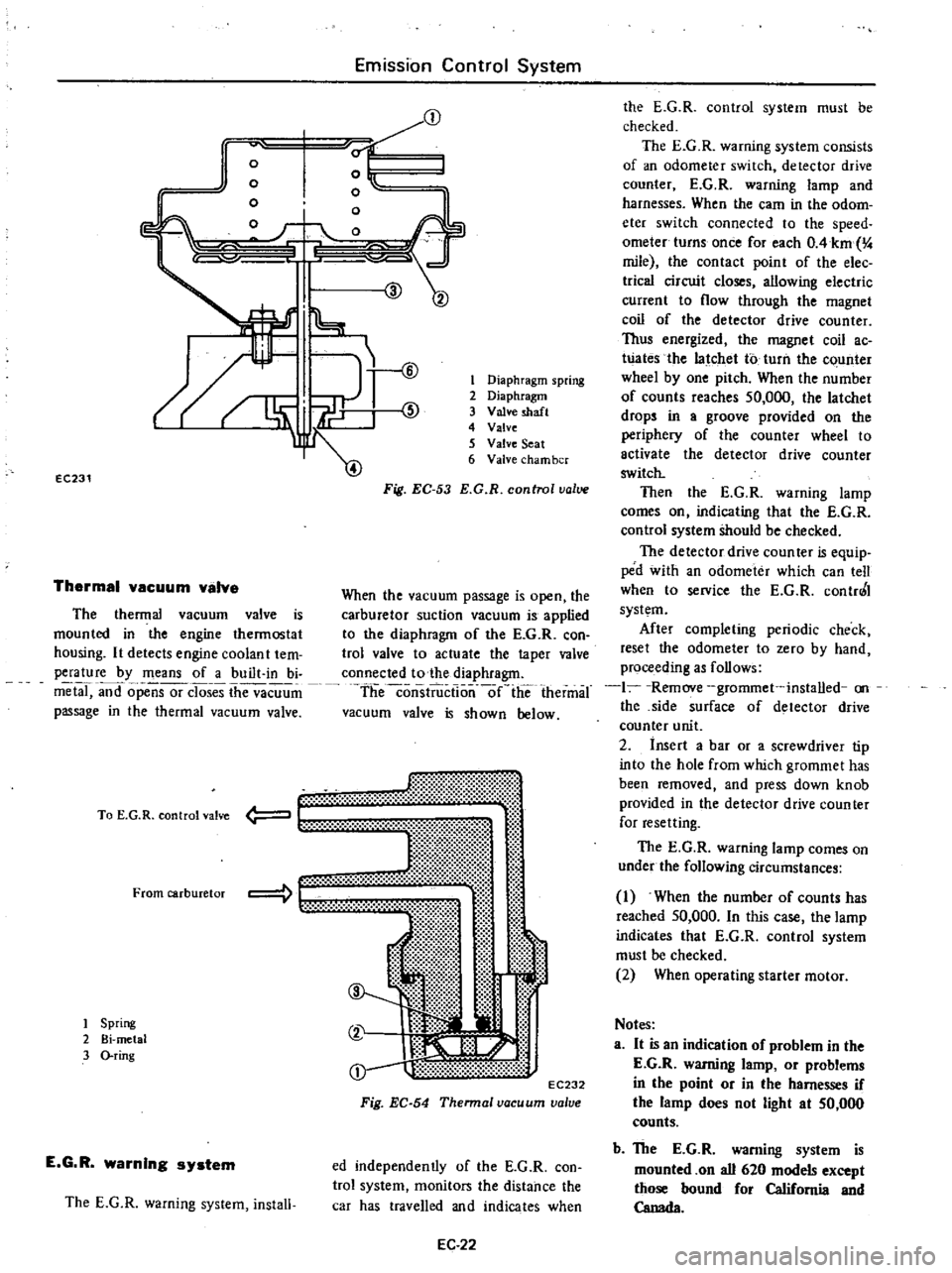
The
thermal
vacuum
valve
is
mounted
in
the
engine
thermostat
housing
It
detects
engine
coolan
t
tem
perature
by
means
of
a
built
in
bi
metal
and
opensor
closes
the
vacuum
passage
in
the
thermal
vacuum
valve
mt
li
t
00
t
EC232
Fig
EC
54
Thennal
vacuum
valve
To
E
G
R
control
valve
From
carburetor
1
Spring
2
Bi
metal
3
O
ring
E
G
R
warning
system
The
E
G
R
warning
system
install
1
Diaphragm
spring
2
Diaphragm
3
Valve
shaft
4
Valve
5
Valve
Seat
6
Valve
cham
ber
Fig
EC
53
E
G
R
control
value
When
the
vacuum
passage
is
open
the
carburetor
suction
vacuum
is
applied
to
the
diaphragm
of
the
E
G
R
con
trol
valve
to
actuate
the
taper
valve
connected
to
the
diaphragm
theconsiiiictlo
nlie
thermal
vacuum
valve
is
shown
below
ed
independently
of
the
E
G
R
con
trol
system
monitors
the
distance
the
car
has
travelled
and
indicates
when
EC
22
the
E
G
R
control
system
must
be
checked
The
E
G
R
warning
system
consists
of
an
odometer
switch
detector
drive
counter
E
G
R
warning
lamp
and
harnesses
When
the
earn
in
the
odom
eter
switch
connected
to
the
speed
ometer
turns
once
for
each
OAkm
4
mile
the
contact
point
of
the
elec
trica
circuit
closes
allowing
electric
current
to
flow
through
the
magnet
coil
of
the
detector
drive
counter
Thus
energized
the
magnet
coil
ac
Wates
the
latchet
to
turn
the
c
unter
wheel
by
one
pitch
When
the
number
of
counts
reaches
50
000
the
latchet
drops
in
a
groove
provided
on
the
periphery
of
the
counter
wheel
to
activate
the
detector
drive
counter
switch
Then
the
E
G
R
warning
lamp
comes
on
indicating
that
the
E
G
R
control
system
Should
be
checked
The
detector
drive
coun
teT
is
equip
ped
with
an
odometer
which
can
tell
when
to
service
the
E
G
R
contr0
I
system
After
completing
periodic
check
reset
the
odometer
to
zero
by
hand
proceeding
as
follows
1
Remove
grommet
installed
on
the
side
surface
of
detector
drive
counter
unit
2
insert
a
bar
or
a
screwdriver
tip
into
the
hole
from
which
grommet
has
been
removed
and
press
down
knob
provided
in
the
detector
drive
counter
for
resetting
The
E
G
R
warning
lamp
comes
on
under
the
following
circumstances
1
When
the
number
of
counts
has
reached
50
000
In
this
case
the
lamp
indicates
that
E
G
R
control
system
must
be
checked
2
When
operating
starter
motor
Notes
a
It
is
an
indication
of
problem
in
the
E
G
R
warning
lamp
or
problems
in
the
point
or
in
the
harnesses
if
the
lamp
does
not
light
at
50
000
counts
b
The
E
G
R
warning
system
is
mounted
on
all
620
models
except
those
bound
for
California
and
Canada
Page 156 of 537
1
1
I
I
I
1
v
v
I
I
I
I
I
I
I
I
I
I
I
I
I
I
I
I
I
I
I
I
I
L
0
I
Magnet
coil
Detector
drive
counter
REMOVAL
AND
INSTALLATION
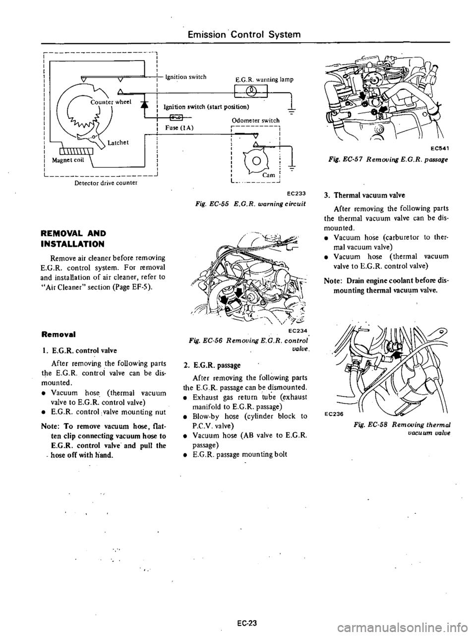
Remove
air
cleaner
before
removing
E
G
R
control
system
For
removal
and
installation
of
air
cleaner
refer
to
Air
Cleaner
section
Page
EF
S
Removal
I
E
G
R
control
valve
After
removing
the
following
parts
the
E
G
R
controi
valve
can
be
dis
mounted
Vacuum
hose
thermal
vacuum
valve
to
E
G
R
control
valve
E
G
R
control
valve
mounting
nut
Note
To
remove
vacuum
hose
flat
ten
clip
connecting
vacuum
hose
to
E
G
R
control
valve
and
pull
the
hose
off
with
hand
Emission
Control
System
Ignition
switch
E
G
R
warning
lamp
f
1
Ignition
switch
start
position
Fuse
1
A
Odometer
switch
r
I
I
I
I
v
I
I
I
i
lQ
U
1
mi
L
J
EC233
Fig
EC
55
E
G
R
warning
circuit
EC234
Fig
EC
56
Removing
KG
R
control
valve
2
E
G
R
pass
ge
After
removing
the
following
parts
the
E
G
R
passage
can
be
dismounted
Exhaust
gas
return
tube
exhaust
manifold
to
E
G
R
passage
B1ow
by
hose
cylinder
block
to
P
C
v
valve
Vacuum
hose
AB
valve
to
E
G
R
passage
E
G
R
passage
mounting
bolt
EC
23
EC541
Fig
EC
57
Removing
E
G
R
passage
3
Thermal
vacuum
valve
After
removing
the
following
parts
the
thermal
vacuum
valve
can
be
dis
mounted
Vacuum
hose
carburetor
to
ther
mal
vacuum
valve
Vacuum
hose
thermal
vacuum
valve
to
E
G
R
control
valve
Note
Drain
engine
coolant
before
dis
mounting
thermal
vacu
m
valve
Fig
EC
58
Removing
thermal
vacu
um
valve