light DATSUN PICK-UP 1977 Manual Online
[x] Cancel search | Manufacturer: DATSUN, Model Year: 1977, Model line: PICK-UP, Model: DATSUN PICK-UP 1977Pages: 537, PDF Size: 35.48 MB
Page 462 of 537

Fuse
M
Body
Electrical
System
YR
Meter
voltage
regulator
Water
temperature
gauge
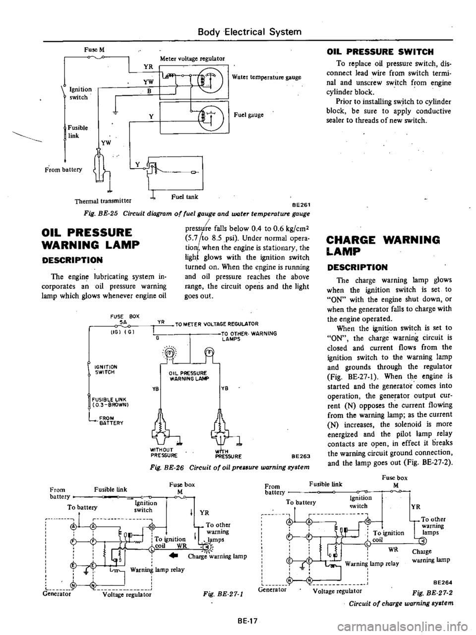
BE261
Circuit
diagram
of
fuel
gauge
and
water
temperature
gauge
pressure
falls
below
0
4
to
0
6
kg
cm2
5
7
to
8
5
psi
Under
normal
opera
tion
when
the
engine
is
stationary
the
ligh
glows
with
the
ignition
switch
turned
on
When
the
e
gine
is
running
and
oil
pressure
reaches
the
above
range
the
circuit
opens
and
the
light
goes
out
Ignition
switch
YW
B
1
Y
I
Fusible
link
YW
t
Thermal
transmitter
L
Fig
BE
25
OIL
PRESSURE
WARNING
LAMP
DESCRIPTION
The
engine
lubricating
system
in
corporates
an
oil
pressure
warning
lamp
which
glows
whenever
engine
oil
FUSE
BOX
SA
IGJ
G
YR
I
G
IGNITION
SWITCH
YB
I
FUSIBLE
LINK
O
J
BROWN
lffi
l
f
r@
Fuel
gauge
Fuel
tank
TO
METER
VOLTAGE
REGULATOR
TO
OTHER
WARNING
lAMPS
jt
Oil
PRESSURE
WARNING
LAhlP
YB
tl
PRESSURE
PRESSURE
FROM
BATTERY
BE263
Fig
BE
26
Circuit
of
oil
prelSure
warning
system
Fusible
link
Fuse
box
M
OIL
PRESSURE
SWITCH
To
replace
oil
pressure
switch
dis
connect
lead
wire
from
switch
termi
nal
and
unscrew
switch
from
engine
cylinder
block
Prior
to
installing
switch
to
cylinder
block
be
sure
to
apply
conductive
sealer
to
threads
of
new
switch
CHARGE
WARNING
LAMP
DESCRIPTION
The
charge
warning
lamp
glows
when
the
ignition
switch
is
set
to
ON
with
the
engine
shut
down
or
when
the
generator
falls
to
charge
with
the
engine
operated
When
the
ignition
switch
is
set
to
ON
the
charge
warning
circuit
is
closed
and
current
flows
from
the
ignition
switch
to
the
warning
lamp
and
grounds
through
the
regulator
Fig
BE
27
1
When
the
engine
is
started
and
the
generator
comes
into
operation
the
generator
output
cur
rent
N
opposes
th
current
flowing
from
the
warning
lamp
as
the
current
N
increases
the
solenoid
is
more
energized
and
the
pilot
lamp
relay
contacts
are
open
in
effect
it
oreaks
the
warning
circuit
ground
connection
and
the
lamp
goes
out
Fig
BE
27
2
Fusible
link
Fuse
box
M
From
battery
To
battery
Ig
ition
ru
nu
swllch
A
A
To
other
warning
h
To
ignition
IQlamps
i
J
r
coil
WR
t
I
j
Charge
warning
lamp
T
T
I
War
lamp
relay
J
I
Generator
v
it
ge
e
g
bt
From
battery
To
battery
Ignition
witch
J
i
L
r
t
ft
ignition
r
Glj
fCOil
WR
f
I
Warning
lamp
relay
Generator
Voltage
regulator
I
YR
Fig
BE
27
1
BE17
YR
UTO
other
warrung
lamps
Charge
warning
lamp
BE264
Fig
BE
27
2
Circuit
of
charge
warning
system
Page 464 of 537

Condition
Inaccurate
speedometer
indication
Inaccurate
odometer
operation
Body
Electrical
System
Probable
cause
Inoperative
speedometer
Improperly
meshed
second
and
third
gear
worn
gears
Faulty
feeding
due
to
deformed
odometer
and
pinion
carrier
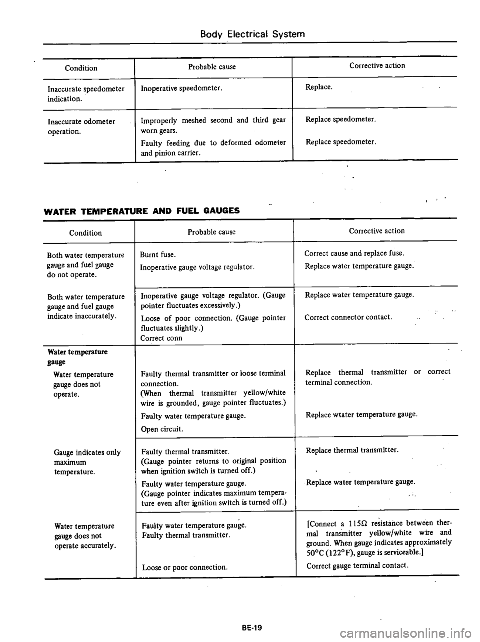
WATER
TEMPERATURE
AND
FUEL
GAUGES
Condition
Both
water
temperature
gauge
and
fuel
gauge
do
not
operate
Both
water
temperature
gauge
and
fuel
gauge
indicate
inaccurately
Water
temperature
gauge
Water
temperature
gauge
does
not
operate
Gauge
indicates
only
maximum
temperature
Water
temperature
gauge
does
not
operate
accurately
Probable
cause
Burnt
fuse
Inoperative
gauge
voltage
regulator
Inoperative
gauge
voltage
regulator
Gauge
pointer
fluctuates
excessively
Loose
of
poor
connection
Gauge
pointer
fluctuates
slightly
Correct
conn
Faulty
thermal
transmitter
or
loose
terminal
connection
When
thermal
transmitter
yellow
white
wire
is
grounded
gauge
pointer
fluctuates
Faulty
water
temperature
gauge
Open
circuit
Faulty
thermal
transmitter
Gauge
pointer
returns
to
original
position
when
ignition
switch
is
turned
off
Faulty
water
temperature
gauge
Gauge
pointer
indicates
maximum
tempera
ture
even
after
ignition
switch
is
turned
off
Faulty
water
temperature
gauge
Faulty
thermal
transmitter
Loose
or
poor
connection
BE
19
Corrective
action
Replace
Replace
speedometer
Replace
speedometer
Corrective
action
Correct
cause
and
replace
fuse
Replace
water
temperature
gauge
Replace
water
temperature
gauge
Correct
connector
contact
Replace
thermal
transmitter
or
correct
terminal
connection
Replace
wtater
temperature
gauge
Replace
thermal
transmitter
Replace
water
temperature
gauge
Connect
a
usn
resistance
between
ther
mal
transmitter
yellow
white
wire
and
ground
When
gauge
indicates
approximately
500C
i220F
gauge
is
serviceable
Correct
gauge
terminal
contact
Page 465 of 537

Condition
Fuel
gauge
Fuel
gauge
does
not
operate
Pointer
indicates
only
F
position
Body
Electrical
System
Probable
cause
Faulty
tank
unit
or
loose
unit
terminal
connection
pointer
indicates
a
half
level
when
a
35U
resistance
is
connected
between
tank
unit
yellow
wire
and
ground
Faulty
fuel
gauge
Poor
or
loose
cormection
Open
circuit
Faulty
tank
unit
pointer
lowers
below
E
mark
when
igni
tion
switch
Is
turned
off
Faulty
fuel
gauge
pointer
still
indicates
F
position
when
ignition
switch
is
turned
off
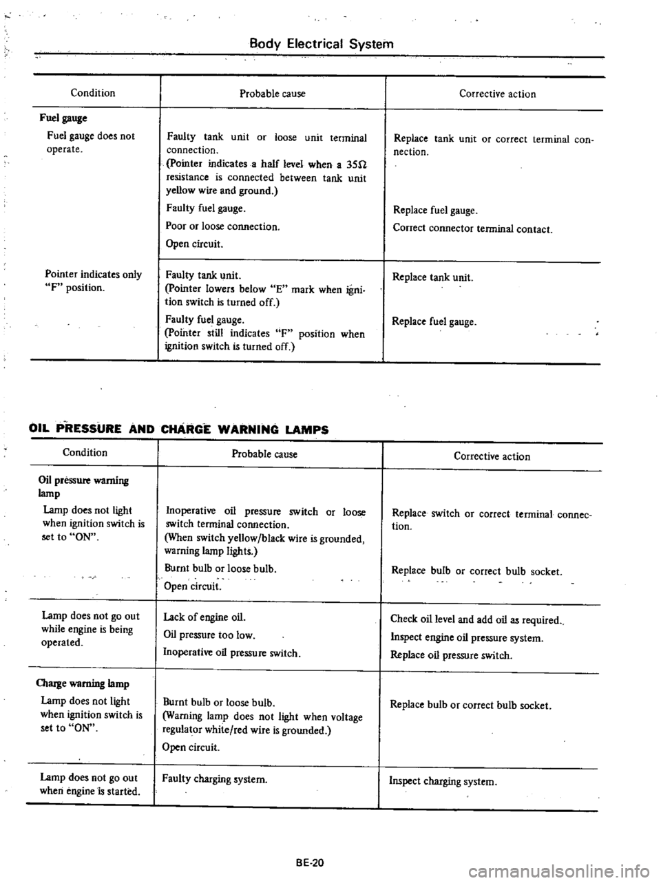
OIL
P
RESSURE
AND
CHARGE
WARNING
LAMPS
Condition
Oil
pressure
wamiug
lamp
Lamp
does
not
light
when
ignition
switch
is
set
to
ON
Lamp
does
not
go
out
while
engine
is
being
operated
OIarge
warning
lamp
Lamp
does
not
light
when
ignition
switch
is
set
to
ON
Lamp
does
not
go
out
when
engine
is
started
Probable
cause
Inoperative
oil
pressure
switch
or
loose
switch
terminal
connection
When
switch
yellow
black
wire
is
grounded
warning
lamp
lights
Burnt
bulb
or
loose
bulb
Open
circuit
Lack
of
engine
oil
Oil
pressure
too
low
Inoperative
oil
pressure
switch
Burnt
bulb
or
loose
bulb
Warning
lamp
does
not
light
when
voltage
regulator
white
red
wire
is
grounded
Open
circuit
Faulty
charging
system
BE
20
Corrective
action
Replace
tank
unit
or
correct
terminal
con
nection
Replace
fuel
gauge
Conect
connector
terminal
contact
Replace
tank
unit
Replace
fuel
gauge
Corrective
action
Replace
switch
OJ
correct
terminal
connee
tion
Replace
bulb
or
correct
bulb
socket
Check
oil
level
and
add
oil
as
required
Inspect
engine
oil
pressure
system
Replace
oil
pressure
switch
Replace
bulb
or
correct
bulb
socket
Inspect
charging
system
Page 478 of 537

Body
Electrical
System
TROUBLE
DIAGNOSES
AND
CORRECTIONS
HORN
Condition
Horn
does
not
operate
Horn
sounds
continuously
Reduced
volume
and
or
tone
quality
Probable
cause
Discharged
battery
Measure
specific
gravity
of
electrolyte
Burnt
fuse
Faulty
horn
button
contact
Horn
sounds
when
horn
relay
terminal
s
is
grounded
Inoperative
horn
relay
Horn
sounds
when
B
and
H
horn
relay
tenninals
are
connected
with
a
test
lead
Damaged
horn
or
loose
horn
terminal
con
nection
Short
circuited
horn
button
and
or
horn
button
lead
wire
When
light
green
lead
wire
is
disconnected
from
horn
relay
terminal
s
horn
stops
to
sound
Inoperative
horn
relay
Loose
or
poor
connector
contact
Fuse
relay
horn
and
or
horn
button
Damaged
horn
BE
33
Corrective
action
Recharge
or
replace
battery
Correct
cause
and
replace
fuse
Repair
horn
button
Replace
horn
relay
Correct
horn
te
inal
onnection
or
replace
horn
Repair
horn
button
or
its
wiring
Replace
horn
relay
Repair
Replace
Page 484 of 537

m
W
D
to
l
l
0
c
l
l
s
Q
3
For
Automatic
Transmission
LB
B
For
Manual
Transmission
m
For
Automatic
Transmission
COLOR
CODE
B
Black
BI
Brown
G
Green
L
Blue
Lg
Light
green
R
Red
W
White
Y
Yellow
BW
Black
with
white
stripe
LgR
Light
green
with
red
stripe
BY
RB
RB
B
WB
RB
YB
2
RB
I
B
1
BW
r
BY
LB
For
Automatic
Transmission
to
o
c
m
r0
O
O
Dl
For
Manual
Transmission
@
CJ
lti
3
RB
fB
BY
YB
RB@RB
YB
BY
1
To
kickdown
solenoid
fOT
Automatic
Transmission
2
To
reverse
switch
for
Manual
Tranmission
3
To
inhibitor
switch
for
Automatic
Transmission
4
To
oil
pressure
switch
5
To
starter
motor
6
To
engine
room
harness
for
Manual
Transmission
7
To
engine
room
harness
for
Automatic
Transmission
Page 485 of 537

m
J
c
@
@
r
1
I
I
I
II
U
j
J
r
U
I
IT
L
U
L
L
@
Qj
flll
I
1
I
I
1
lL
to
t
l
Q
1
To
room
Jamp
cable
2
To
light
switch
3
To
fuse
4
To
tachometer
or
clock
5
To
hazard
flasher
unit
6
To
stop
lamp
switch
7
To
ignition
switch
8
To
hazard
switch
9
To
tU
and
dimmer
switch
10
To
check
connector
11
To
AMP
M
T
only
11
To
combination
instrument
Non
California
mode15
except
for
Canada
13
To
combination
meter
14
To
flasher
unit
IS
To
kickdown
switch
AfT
only
16
To
hand
brake
switch
17
To
heater
motor
18
To
illumination
control
rheostat
19
To
wiper
switch
light
switch
illumination
lamp
20
To
wiper
switch
21
To
cigar
lighter
22
To
heater
control
illumination
lamp
23
To
radio
24
To
heater
control
25
To
belt
and
E
G
R
warning
lamp
Non
California
models
or
floor
te
peratuJe
California
models
26
To
heater
control
illumination
lamp
27
To
buzzer
28
To
belt
warning
timer
U
S
A
Olodels
29
To
indicator
lamp
AfT
only
30
To
cooler
harness
31
To
wiptr
motor
32
To
door
switch
R
H
33
To
engine
compartment
harness
34
To
floor
harness
E
m
S
@
o
J
o
Q
m
CD
n
Ql
en
I
i
3
Page 489 of 537

Body
Electrical
System
TROUBLE
SHOOTING
GUIDE
Condition
Warning
lamp
does
not
light
in
START
posi
tion
of
ignition
switch
Probable
cause
Burnt
or
loose
bulb
Faulty
f1o
r
temperature
relay
Loose
connection
or
open
circuit
BE
44
Corrective
action
Replace
bulb
or
correct
bulb
socket
Conduct
continuity
test
and
repair
or
reo
place
Refer
to
Section
EC
Check
wiring
and
or
repair
if
necessary
Page 495 of 537

1
I
6
I
BA
RY
i
Air
Conditioning
BW
c
J
BW
n
B
m
00
L
ELECTRIC
FUEL
PUMP
oB
tl
b@
L
t
FROM
LIGHT
SWITCH
c
J
LW
2
L
rRL
fZP
W
I
FUSE
15A
J
D
CJ
B
1
COMPRESSOR
RELAY
B
GL
I
lL
GL1J
ILLUMINATION
CONTROL
RHEOSTAT
3
ILLUMINATION
LAMP
I
I
MAIN
RELAY
FAN
SWITCH
I
r
1
UE
H
I
I
THERMO
SWITCH
COLOR
CODE
@
IC
PRESSU
1
rlTCH
D
D
G
c
J
oc
I
m
f
F
I
C
D
SOLENOID
COMPRESSOR
FUSE
LR
I
BW
O
W
ov
J
I
IG
0
0
OVJ
AC
6
B
BW
L
LW
LR
W
G
GL
RL
Black
Black
with
white
stripe
Blue
Blue
with
white
stripe
Blue
with
red
stripe
White
Green
Green
with
blue
stripe
Red
with
blue
stripe
IG
BW
t
1
n
L
IGNITION
SWITCH
AC727
Fig
A
C
B
Wiring
diagram
of
air
conditioner
system
Page 501 of 537

DISCHARGING
SYSTEM
The
pressurized
refrigerant
gas
Ul
side
system
must
be
discharged
to
a
pressure
approaching
atmospheric
pressure
prior
to
evacuating
refrigerant
inside
system
This
operation
should
be
made
to
permit
safe
re
oval
when
replacing
system
components
I
Close
high
and
low
pressure
valves
of
manifold
gauge
fully
2
Connect
two
charging
hoses
of
manifold
gauge
to
their
respective
service
valves
3
Open
both
manifold
gauge
valves
slightly
and
slowly
discharge
refriger
ant
from
system
See
Figure
AC
17
Note
Do
not
allow
refrigerant
to
rush
out
Otherwise
compressor
oil
will
be
discharged
along
with
re
frigerant
AC735
Fig
AC
17
Discharging
system
Caution
Protect
fingers
with
cloth
against
frostbite
by
refrigerant
when
connecting
the
charging
hose
to
the
service
valve
or
disconnecting
it
therefrom
Air
Conditioning
EVACUATING
SYSTEM
1
Connect
high
and
low
pressure
charging
hoses
of
manifold
gauge
to
their
respective
service
valves
of
sys
tern
and
d
ischarge
refrigerant
from
system
Refer
to
Discharge
System
2
When
refrigerant
has
been
dis
charged
to
a
pressure
approaching
at
mospheric
pressure
connect
center
charging
hose
to
a
vacuum
pump
3
Close
both
valves
of
manifold
gauge
fully
Then
start
vacuum
pump
4
Open
low
pressure
valve
and
suck
old
refrigerant
from
ystem
See
Figure
AC
18
S
When
low
pressure
gauge
reading
has
reached
to
approximately
500
mm
Hg
20
in
Hg
slowly
open
high
pressure
valve
See
Figure
AC
19
6
When
pressure
inside
system
has
dropped
to
710
mm
Hg
28
in
Hg
fully
close
both
of
valves
of
manifold
gauge
and
stop
vacuum
pump
Let
stand
it
for
5
to
10
minutes
in
this
state
and
confirm
that
the
reading
does
not
rise
Notes
a
The
low
pressure
gauge
reads
lower
by
2S
mm
Hg
I
in
Hg
per
a
300
m
1
000
ft
elevation
Perform
evacu
ation
according
to
the
following
table
Elevation
m
ft
Vacuum
of
system
mm
Hg
in
Hg
0
0
300
I
000
600
2
000
900
3
000
710
28
68S
27
660
26
635
25
Note
Values
show
readings
of
the
low
pressure
gauge
AC
12
b
The
rate
of
ascension
of
the
low
pressure
gauge
should
be
less
than
2S
mm
Hg
I
in
Hg
in
five
min
utes
If
the
pressure
rises
or
the
specified
negative
pressure
can
not
be
obtained
there
is
a
leak
in
the
system
In
this
case
immediately
charge
system
with
refrigerant
and
repair
the
leak
de
scribed
in
the
following
I
Confirm
that
both
valves
of
manifold
gauge
are
fully
closed
and
then
disconnect
center
charging
hose
from
vacuum
pump
2
Connect
center
hose
to
can
tap
in
place
of
vacuum
pump
Attach
refrigerant
can
to
can
tap
and
pass
refrigerant
to
manifold
gauge
3
Loosen
the
connection
of
center
fitting
of
manifold
gauge
to
purge
air
from
center
hose
4
Open
low
pressure
valve
of
mani
fold
gauge
and
charge
refrigerant
into
system
After
one
can
about
0
4
kg
I
Ib
of
refrigerant
has
been
charged
into
system
close
low
pressure
valve
5
Check
for
refrigerant
leakage
with
a
leak
detector
Repair
any
leak
ages
found
Refer
to
Checking
for
Leaks
and
Refrigerant
Leaks
6
Confirm
that
both
valves
of
manifold
gauge
are
fully
closed
and
then
change
center
charging
hose
from
can
tap
to
vacuum
pump
7
Open
high
and
low
pressure
valves
and
operate
vacuum
pump
to
suck
refrigerant
from
system
When
the
pressure
in
system
has
dropped
to
710
mm
Hg
28
in
Hg
fully
close
both
valves
of
manifold
gauge
7
The
above
operation
completes
evacuation
of
system
Next
charge
refrigerant
Refer
to
Charging
Refrig
erant
Page 504 of 537

7
After
the
specified
amount
of
refrigerant
has
been
charged
into
sys
tem
close
manifold
gauge
valves
Then
detach
charging
hoses
from
service
valves
of
system
Be
sure
to
install
valve
cap
to
service
valve
8
Confirm
that
there
are
no
leaks
in
system
by
checking
with
a
leak
detec
tor
Refer
to
Checking
for
Leaks
Note
Conducting
a
performance
test
prior
to
removing
manifold
gauge
is
a
good
sen
ice
operation
Refer
to
Performance
Test
CHECKING
FOR
LEAKS
Conduct
a
leak
test
whenever
leak
age
of
refrigerant
is
suspected
and
when
conducting
service
operations
which
are
accompanied
by
disassembly
Dr
loosening
of
connection
fittings
Air
Conditioning
Refrigerant
is
a
colorless
odorless
gas
and
leakage
from
system
is
diffi
cult
to
detect
Accordingly
the
use
of
a
leak
detector
facilitates
check
for
leaks
Two
methods
of
checking
are
available
one
employs
a
halide
leak
detector
which
burns
propane
gas
or
butane
gas
and
the
other
is
an
electric
type
leak
detector
HALIDE
LEAK
DETECTOR
Since
the
propane
leak
detector
and
butane
leak
detector
are
the
same
in
respect
to
their
operation
this
section
describes
the
operation
of
the
propane
leak
detector
The
copper
screen
is
heated
by
the
burning
of
propane
Refrigerant
gas
decomposes
to
color
the
flame
when
it
contacts
the
heated
screen
The
gas
to
be
checked
is
drawn
into
the
sampling
tube
and
sent
out
to
the
burner
A
refrigerant
leak
can
clearly
be
detected
by
variations
in
the
color
of
the
flame
Propane
type
NO
LEAK
SMALL
LEAK
LARGE
LEAK
Greenish
blue
Yellow
Purple
AC010
1
Copper
reaction
plate
2
Flame
adjusting
lines
3
Burner
4
Sampling
tube
5
Strainer
6
Gas
bomb
7
Flame
adjuster
Fig
A
C
25
Checking
for
leak
Butane
type
Pale
blue
Bright
blue
Vivid
green
AC
15
I
Discharge
refrigerant
in
one
or
two
seconds
to
ascertain
that
system
has
a
sufficient
pressure
needed
for
leak
detection
Charge
with
04
kg
I
lb
of
refrigerant
if
necessary
2
Light
leak
detector
Adjust
the
height
of
the
ilame
between
flame
adjusting
lines
at
the
top
and
bottom
of
combustion
tube
A
reaction
plate
will
immediately
become
red
hot
3
Place
the
end
of
sampling
tube
near
the
point
of
the
suspected
leak
in
system
Notes
a
Since
refrigerant
gas
is
heavier
than
air
small
leaks
can
b
easily
detect
ed
by
placing
sampling
tube
direct
ly
below
the
check
point
b
Suitable
ventilation
is
required
If
refrigerant
gas
is
mixed
with
the
surrounding
air
leak
detector
will
always
indicate
a
response
and
detection
of
the
actual
leak
will
be
difficult
c
Never
bold
leak
detector
at
an
angle
Cautions
a
Never
inhale
the
fumes
produced
by
combustion
of
refrigerant
gas
since
they
are
toxic
b
Never
use
halide
torch
in
a
place
where
combustible
or
explosive
gas
is
present
4
The
ilame
will
be
almost
colorless
when
there
is
no
refrigerant
gas
being
burned
When
there
is
a
small
refriger
ant
gas
leak
the
ilame
will
be
green
or
yellowgreen
When
refrigerant
gas
leak
age
is
large
the
ilame
will
be
brilliant
blue
or
purple
Since
the
color
of
the
ilame
will
be
yellow
when
dust
is
being
burned
Or
there
is
aging
scale
on
copper
reaction
plate
always
keep
the
strainer
of
sampling
tube
and
reaction
plate
clean
5
Major
check
points
I
Compressor
Compressor
shaft
seal
rotate
the
compressor
by
hand
Oil
filler
plug
Flexible
hose
connections
Rear
cover
and
side
cover
gaskets
Service
valve
2
Condenser
Condenser
pipe
fitting
Condenser
inlet
and
outlet
pipe
connections
I