light DATSUN PICK-UP 1977 Workshop Manual
[x] Cancel search | Manufacturer: DATSUN, Model Year: 1977, Model line: PICK-UP, Model: DATSUN PICK-UP 1977Pages: 537, PDF Size: 35.48 MB
Page 314 of 537
Using
the
tester
check
the
two
black
yellow
BY
wires
from
the
in
hibitor
switch
in
the
ranges
N
and
I
and
the
tw
re
d
black
RBj
wir
s
in
the
range
R
for
continuity
Turn
range
select
lever
in
both
directions
from
each
lever
set
position
and
check
each
continuity
range
It
is
normal
if
the
electricity
is
on
while
the
lever
is
within
an
angle
of
about
30
on
both
sides
from
each
lever
set
line
How
ever
if
its
continl
ity
range
is
obvious
ly
unequal
on
both
sides
adjustment
is
required
If
any
malfunction
is
found
un
screw
the
fastening
nut
of
the
range
selector
lever
and
two
fastening
bolts
of
the
switch
body
and
then
remove
the
machine
screw
under
the
switch
body
Adjust
the
manual
shaft
correct
ly
to
the
position
N
by
means
of
the
selector
lever
When
the
slot
of
the
shaft
becomes
vertical
the
detent
works
to
position
the
shaft
correctly
with
a
clicking
sound
MSlVe
the
switch
slightly
asj
Je
so
that
the
screw
hole
will
be
aligned
with
the
pin
hole
of
the
internal
rotor
combined
with
the
manual
shaft
and
check
their
alignment
by
inserting
a
1
5
mm
0
059
in
diameter
pin
into
the
holes
If
the
alignment
is
correct
fasten
the
switch
body
with
the
bolts
pull
out
the
pin
tighten
up
the
screw
in
the
hole
and
fasten
the
selector
lever
as
before
Check
the
continuity
again
with
the
tester
If
the
malfunc
tion
still
remains
replace
the
inhibitor
switch
Chcck
whether
the
reverse
lamp
and
the
starter
motor
operate
normal
ly
in
these
ranges
If
Ihere
is
any
lrouble
first
check
the
linkage
If
no
fault
is
found
in
the
linkage
check
the
inhibitor
switch
Separate
the
manual
lever
from
Ihe
remote
control
selector
rod
and
turn
the
range
selcct
lever
to
N
Note
In
the
position
N
the
slot
of
the
manual
shaft
is
vertical
STALL
TEST
The
purpose
of
this
test
is
to
check
the
transmission
and
engine
for
trou
ble
by
measuring
the
maximum
num
bers
of
revolutions
of
the
engine
while
Automatic
Transmission
vehicle
is
held
in
a
stalled
condition
The
carburctor
is
in
full
throttle
opera
tion
with
the
selector
lever
in
ranges
f
2
and
I
respectively
Com
pare
the
measured
results
with
the
slandard
values
Components
to
be
tested
and
test
items
I
Clutches
brake
and
band
in
trans
mission
for
slipping
2
Torque
converter
for
proper
fune
tioning
3
Engine
for
overall
properly
STALL
TEST
PROCEDURES
Before
Icsting
c
heck
the
engine
oil
and
torque
converter
oil
warm
up
the
engine
cooling
water
to
suitable
tem
perature
by
running
at
1
200
rpm
with
the
selector
lever
in
the
range
P
for
several
minutes
Warm
up
the
torque
converter
oil
to
suitable
temperature
6010
1000C
140
to
2l20F
I
Mount
the
engine
tachometer
at
a
location
that
allows
good
visibility
fro
the
dri
er
s
seat
and
put
a
mark
on
specified
revolutions
on
the
meter
2
Secure
the
front
and
rear
wheels
with
chocks
and
apply
the
hand
brake
Be
sure
to
depress
the
brake
pedal
fumly
with
the
left
foot
before
de
pressing
the
accelerator
pedal
3
Throw
the
selector
lever
into
the
range
1
4
Slowly
depress
the
accelerator
pedal
until
the
throttle
valvc
is
fully
opened
Quickly
read
and
record
the
engine
revolution
when
the
engine
begins
to
rotate
steadily
and
then
release
the
accelerator
pedal
5
Shift
the
selector
lever
to
N
and
operate
the
engine
at
approxi
mately
1
200
rpm
for
more
than
one
minute
to
cool
down
the
torque
con
ver
ter
oil
and
coolant
6
Make
similar
stall
tests
in
ranges
2
I
and
RIO
Note
The
stall
test
operation
as
speci
f
d
in
item
4
should
be
I
l3de
wiihin
five
seconds
If
it
takes
too
long
the
oil
deteriorates
an
the
clutches
brake
and
band
are
ad
versely
affected
Sufficient
cooling
time
should
be
given
between
each
AT
5O
test
for
the
four
ranges
0
2
I
and
R
JUDGEMENT
High
stall
revolution
more
than
standard
revolution
If
the
engine
revolution
in
stall
condition
is
higher
than
the
standard
values
it
indicates
that
one
or
more
clutches
in
the
transmission
are
slipping
and
therefore
no
further
test
is
required
For
the
following
abnormalities
the
respective
causes
are
presumed
High
rpm
in
all
ranges
low
Iine
pressure
High
rpm
in
D
2
and
I
and
normal
rpm
in
R
Rear
clutch
slipping
High
rpm
in
0
and
normal
rpm
in
I
clutch
slipping
High
rpm
in
R
only
Front
clutch
or
low
and
reverse
brake
slipping
To
determine
which
is
slipping
front
clutch
or
low
and
reverse
brake
a
road
test
is
nceded
If
whilc
coasting
after
starting
with
the
lever
in
1
range
engine
braking
does
not
work
properly
the
low
and
reverse
brake
is
slipping
Otherwise
the
front
clutch
is
slipping
Slipping
of
the
band
brake
is
diffi
cult
to
ascertain
However
if
it
occurs
with
the
lever
in
2
range
engine
revolution
increases
Jp
to
thesarne
level
as
in
I
strange
It
is
impossible
to
check
it
in
the
stall
test
2
and
One
way
2
Standard
stall
revolution
If
the
engine
revolution
in
stall
condition
is
within
the
standard
values
the
control
elements
are
nor
mally
operating
in
the
ranges
0
2
I
and
R
Also
tIle
engine
and
one
way
clutch
of
the
torque
converter
are
normal
in
performance
and
operation
The
one
way
clutch
of
the
torque
converter
however
sometimes
sticks
This
is
determined
in
the
road
test
3
Lower
stall
revolution
than
stand
ard
revolution
If
the
engine
revolution
in
stall
condition
is
lower
than
the
standard
Page 331 of 537
PROPELLER
SHAFT
DIFFERENTIAL
CARRIER
Watch
for
oil
leakage
from
trans
mission
end
Notes
a
Remove
propeller
shaft
carefully
so
as
not
to
damage
spline
sleeve
yoke
and
rear
oil
seal
b
Plug
up
the
opening
in
the
rear
of
rear
extension
housing
to
prevent
oil
from
flowing
out
To
install
reverse
the
foregoing
removal
procedure
1
Align
propeller
shaft
with
com
panion
flange
using
reference
marks
prescribed
in
removal
procedure
and
assemble
with
bolts
Tightening
torque
2
4
to
3
3
kg
m
17
to
24
ft
Ib
2
Insert
bolts
through
the
holes
of
center
beariug
bracket
and
torque
nuts
to
retain
center
bearing
on
cross
member
Tightening
torque
1
6
to
2
2
kg
m
12
to
16
ft
Ib
DISASSEMBLY
AND
ASSEMBLY
Primarily
do
not
disassemble
pro
peller
shaft
because
it
is
balanced
as
an
assembly
However
check
propeller
shaft
with
journal
for
movement
When
journal
does
not
move
smoothly
dis
assemble
1
Mark
propeller
shaft
and
journal
so
that
the
original
combination
can
be
restored
at
assembly
2
Remove
snap
ring
with
a
standard
screwdriver
3
Lightly
tap
base
of
yoke
with
a
hammer
and
withdraw
bearing
race
See
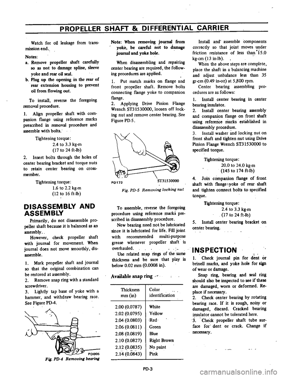
Figure
PD
4
PDOO5
Fig
PD
4
Remo
i
bearing
Note
When
removing
journal
from
yoke
be
careful
not
to
damage
journal
and
yoke
bole
When
disassembling
and
repairing
center
bearing
are
required
the
follow
ing
procedures
are
applied
1
Put
match
marks
on
flange
and
front
propeller
shaft
Remove
bolts
connecting
flange
yoke
to
companion
flange
2
Applying
Drive
Pinion
Flange
Wrench
ST3lS30000
loosen
off
lock
ing
nut
and
remove
center
bearing
See
Figure
PD
5
P0172
ST31530000
Fig
PD
5
Remouing
locking
nut
To
assemble
reverse
the
foregoing
procedure
using
reference
marks
pre
scribed
in
disassembly
procedure
New
bearing
need
not
be
lubricated
since
it
is
lubricated
for
life
Fill
joint
with
recommended
multi
purpose
grease
whenever
propeller
shaft
is
overhauled
Use
related
snap
rings
of
the
same
thickness
and
be
sure
that
play
is
below
0
02
mm
0
0008
in
Available
snap
ring
Thickness
mm
in
Color
identification
2
00
0
0787
2
02
0
079S
2
Q4
0
0803
2
06
0
08
II
2
08
0
0819
2
10
0
0827
2
12
0
83S
2
14
0
0843
White
Yellow
Red
Green
Blue
Right
Brown
No
paint
Pink
PD
3
Install
and
assemble
components
correctly
so
that
joint
moves
under
friction
resistance
of
less
than
is
o
kg
em
13
in
lb
When
the
above
steps
are
complete
place
the
shaft
in
a
balancing
machine
and
adjust
unbalance
less
than
3S
gr
cm
0
49
in
oz
at
S
800
rpm
Center
bearing
assembling
pro
cedures
are
as
follows
I
Install
center
bearing
in
center
bearing
insulator
2
Install
center
bearing
assembly
and
companion
flange
on
front
shaft
usiug
reference
marks
established
in
disassembly
procedure
3
Install
washer
and
locking
nut
on
front
shaft
and
tighten
nut
using
Drive
Pinion
Flange
Wrench
ST3IS30000
to
specified
torque
Tightening
torque
20
0
to
24
0
kg
m
I4S
to
174
ft
lb
4
Join
companion
flange
of
front
shaft
with
f1ange
yoke
of
rear
shaft
and
tighten
connect
bolts
to
specified
torque
Tightening
torque
2
4
to
3
3
kg
m
17
to
24
ft
Ib
S
Install
center
bearing
bracket
on
center
bearing
INSPECTION
I
Check
journal
pin
for
dent
or
brinell
marks
and
yoke
hole
for
sign
of
wear
or
damage
Snap
ring
bearing
and
seal
ring
should
also
be
inspected
to
see
if
these
are
damaged
worn
or
deformed
Re
place
if
necessary
2
heck
center
bearing
by
rotating
bearing
race
If
it
is
rough
noisy
or
damaged
discard
Cracked
bearing
insulator
cannot
be
tolerated
here
3
Check
propeller
shaft
tube
sur
face
for
dent
or
crack
Change
if
necessary
Page 340 of 537
PROPELLER
SHAFf
DIFFERENTIAL
CARR
IER
Ex
2
A
0
B
3
C
I
0
0
E
0
20
mOl
F
0
17
mOl
H
2
Left
side
T
I
A
C
D
H
x
om
0
17S
E
0
I
0
2
x
0
01
0
I7S
0
20
0
I
0
2
x
0
01
0
17S
0
20
3
Om
0
17S
0
20
0
03
0
17S
0
20
O
34S
mrn
The
correct
shinjs
are
O
OS
plus
0
10
plus
0
20
mrn
thick
Right
side
T2
B
D
H
xO
0l
O
ISO
F
3
0
2
x
om
O
ISO
0
17
3
0
2
x
om
0
150
0
17
S
x
0
01
0
ISO
0
I7
O
OS
0
1S0
0
17
0
37
mrn
The
correct
shims
are
0
07
plus
0
1
0
plus
0
20
mm
thick
Note
If
w1ues
signifying
A
B
C
0
and
H
are
not
given
regard
them
as
zero
and
compute
Aft
assembly
check
to
see
that
preload
and
backlash
are
correct
If
not
readjust
Side
bearing
adjusting
shim
Thickness
mm
in
O
OS
0
0020
0
07
0
0028
0
1
0
0
0039
0
20
0
0079
0
50
0
0197
2
Fit
determined
side
bearing
adjusting
shim
on
differential
case
and
press
fit
left
and
right
side
bearing
inner
races
on
it
using
Side
Bearing
Drift
ST33230000
and
Adapter
ST33061000
3
Install
differential
case
assembly
into
gear
carrie
tapping
with
a
rubber
mallet
4
Align
mark
on
bearing
cap
with
that
on
gear
carrier
and
install
bearing
cap
on
carrier
And
tight
n
bolts
to
specified
torque
Tightening
torque
4
0
to
S
O
kg
m
29
to
36
fHb
S
Measure
ring
gear
to
drive
pinion
backlash
If
backlash
is
too
small
remove
shims
from
left
side
and
add
them
to
right
side
To
reduce
backlash
remove
shims
from
right
side
and
add
them
to
left
side
Backlash
O
1S
to
0
20
mrn
0
00S9
to
0
0079
in
Fig
PD
22
Mccuuring
back1aah
6
At
the
same
time
check
side
bearing
preload
Bearing
preload
should
read
12
0
to
20
0
kg
cm
10
to
17
in
lb
of
rotating
torque
3
S
to
S
8
kg
7
7
to
12
8
Ib
at
ring
gear
bolt
hole
PD
12
If
preload
does
not
accord
with
this
specification
adjust
it
with
side
bear
ing
shims
7
Check
and
adjust
the
tooth
con
tact
pattern
of
ring
gear
and
drive
pinion
I
Thoroughly
clean
ring
and
drive
pinion
gear
teeth
2
Paint
ring
gear
teeth
lightly
and
evenly
with
a
mixture
of
ferric
oxide
and
gear
oil
to
produce
a
contact
pattern
3
Rotate
pinion
through
several
revolutions
in
the
forward
and
reverse
directions
until
a
defmite
contact
pat
tern
is
developed
on
ring
gear
4
When
contact
pattern
is
incor
rect
readjust
thickness
of
adjusting
washer
S
Incorrect
contact
pattern
of
teeth
can
be
adjusted
in
the
following
manner
a
Heel
contact
To
correct
increase
thickness
of
pinion
height
adjusting
washer
in
order
to
bring
drive
pinio
close
to
ring
gear
P0193
Fig
PD
23
Hul
contact
b
Toe
contact
To
correct
reduce
thickness
of
pinion
height
adjusting
washer
in
order
to
make
drive
pinion
go
away
from
ring
gear
P0194
1
Fig
PD
24
To
contact
Page 352 of 537
The
design
of
the
front
suspension
adopts
the
independent
double
wishbone
type
suspension
used
the
torsion
bar
spring
Both
the
upper
and
lower
links
are
installed
on
the
bracket
which
is
welded
on
the
frame
A
1d
the
above
links
swing
to
allow
the
knuckle
spindle
to
move
freely
in
a
vertical
dimension
The
top
and
bottom
of
the
knuckle
spindle
support
are
connected
to
the
upper
link
through
rubber
bushing
and
to
the
lower
lick
through
screw
bushing
The
tension
rod
held
by
the
brack
ets
on
the
chassis
frame
and
lower
lick
wiih
rubber
bushings
bears
the
force
of
fore
and
aft
direction
The
front
end
of
the
torsion
bar
spring
is
installed
to
the
torque
arm
which
attaches
to
the
lower
link
The
opposite
end
is
installed
to
the
spring
anchor
that
secures
to
chassis
frame
firmly
The
both
ends
of
the
torsion
bar
spring
are
serrated
The
shock
absorber
is
double
action
telescopic
hydraulic
type
The
upper
stem
is
attached
to
the
bracket
of
the
chassis
frame
The
lower
insulated
bracket
is
bolted
to
the
lower
lick
The
bumper
rubber
secured
to
the
bracket
Of
the
frame
limits
the
verti
cal
motion
of
the
suspension
lick
The
knuckle
spindle
is
connecied
to
the
k
ufkle
spindle
arm
by
the
king
pin
The
king
pin
bushings
are
fitted
to
the
upper
and
lower
arm
portIOns
of
the
knuckle
spindle
and
seals
are
provided
at
the
portions
mentioned
to
keep
water
and
dirt
from
enteri
g
The
knuckle
arm
is
connected
to
the
lower
end
of
the
knuckle
spindle
to
transmit
ttLe
movement
of
the
steering
wheel
to
the
knuckle
spindle
The
wheel
hub
is
supported
by
two
taper
roller
bearings
on
the
knuckle
spindle
Tlie
brake
drum
and
wheel
are
secured
to
ihe
hub
by
the
hub
bolts
Front
Axle
Front
Suspension
FRONT
AXLE
REMOVAL
AND
INSTALLATION
Removal
I
Jack
up
and
support
vehicle
on
the
stands
at
the
frame
in
a
safe
manner
2
Remove
front
wheel
3
Re
ove
brake
hose
together
with
connector
from
wheel
cylinder
4
Remove
brake
drum
S
Remove
hub
cap
and
then
remove
cotter
pin
adjusting
cap
and
spindle
nut
from
knuckle
spindle
6
Remove
wheel
hub
outer
and
inner
wheel
bearings
bearing
washer
and
grease
seal
from
knuckle
spindle
7
Remove
brake
disc
assembly
from
the
flange
of
knuckle
spindle
8
Remove
knuckle
arm
from
knuckle
spindle
9
Remove
king
pin
lock
bolt
FA225
Fig
FA
R
mol1ing
king
pin
loch
nut
10
After
removing
air
breather
re
move
plug
from
the
top
of
king
pin
with
the
following
method
Drill
a
10
5
mm
0
413
in
diameter
hole
on
the
plug
thread
hole
with
a
tap
M
12
1
2S
screw
a
bolt
into
threaded
hole
and
pull
out
the
plug
II
Apply
drift
to
the
top
of
king
pin
and
drive
out
king
pin
along
with
lower
plug
12
Tap
spindle
with
a
soft
haJnmer
and
detach
it
from
knuckle
spindle
support
Take
care
not
io
drop
thrust
bearing
FA
3
FA226
Fig
FA
3
R
moving
knuckle
piridle
Installation
Install
front
axle
in
reverse
se
quence
to
removal
by
noting
the
fol
lowing
matters
Furthermore
when
installing
front
axle
lightly
coat
grease
to
sliding
parts
I
Insert
O
ring
on
the
lower
end
of
knuckle
spindle
support
Install
thrust
bearing
and
spindle
shim
together
with
knuckle
spindle
to
knuckle
spindle
support
In
this
operation
select
spindle
shims
to
obtain
the
specified
clearance
between
knuckle
spindle
and
knuckle
spindle
support
To
measure
the
Clear
ance
with
a
filler
gauge
jack
up
the
bottom
of
spindle
slightly
Standard
clearance
0
1
mOl
0
004
in
or
less
Note
Be
sure
to
iristsll
thrust
bearing
to
face
coverea
side
upward
2
Line
up
locking
bolt
hole
of
knuckle
spindle
support
with
the
notch
in
king
pin
and
secure
lock
bolt
Be
sure
to
check
killJckle
spindle
for
smooth
movement
Be
certain
to
move
knuckie
spindle
smoothly
and
reailjust
shim
if
necessary
In
addition
check
bushings
and
king
pin
as
required
3
Press
fit
plug
to
the
upper
of
knuckle
spindle
Then
install
lower
plug
to
the
lower
knuckle
spindle
Note
Make
sure
to
place
lower
plug
conectly
4
Secure
knuckle
arm
to
knuckle
Page 354 of 537
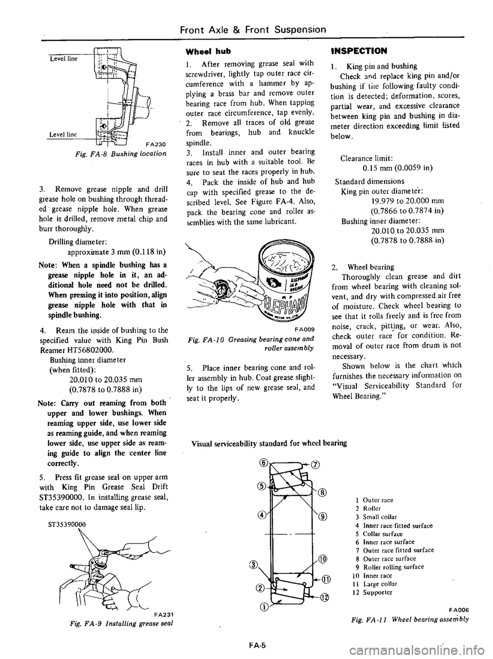
Level
line
Level
line
FA230
Fig
FA
8
Bushing
location
3
Remove
grease
nipple
and
drill
grease
hole
on
bushing
through
thread
ed
grease
nipple
hole
When
grease
hole
is
drilled
remove
metal
chip
and
burr
thoroughly
Drilling
diameter
approximate
3
mOl
0
118
in
Note
When
a
spindle
bushing
has
a
grease
nipple
hole
in
it
an
ad
ditional
hole
need
not
be
drilled
When
pressing
it
into
position
align
grease
nipple
hole
with
that
in
spindle
bushing
4
Ream
the
inside
of
bushing
to
the
specified
value
with
King
Pin
Bush
Reamer
HT56802000
Bushing
inner
diameter
when
fitted
20
010
to
20
03S
mOl
0
7878
to
0
7888
in
Note
Carry
out
reaming
from
both
upper
and
lower
bushings
When
reaming
upper
side
use
lower
side
as
reaming
guide
and
when
reaming
lower
side
use
upper
side
as
ream
ing
guide
to
align
the
center
line
correctly
5
Press
fit
grease
seal
on
upper
arm
with
King
Pin
Grease
Seal
Drift
ST35390000
In
installing
grease
seal
take
care
not
to
damage
seal
lip
51
35390000
FA231
Fig
FA
9
Installing
grease
seal
Front
Axle
Front
Suspension
Wheel
hub
1
After
removing
grease
seal
with
screwdriver
lightly
tap
outer
race
cir
cumference
with
a
hammer
by
ap
plying
a
brass
bar
and
remove
outer
bearing
race
from
hub
When
tapping
outer
race
circumference
tap
evenly
2
Remove
all
traces
of
old
grease
from
bearings
hub
and
knuckle
spindle
3
Install
inner
and
outer
bearing
races
in
hub
with
a
suitable
tool
Be
sure
to
seat
the
races
properly
in
hub
4
Pack
the
inside
of
hub
and
hub
cap
with
specified
grease
to
the
de
scribed
level
See
Figure
FAA
Also
pack
the
bearing
cone
and
roller
as
semblies
with
the
same
lubricant
FA009
Fig
FA
10
Greasing
bearing
cone
and
roller
assembly
5
Place
inner
bearing
cone
and
rol
ler
assembly
in
hub
Coat
grease
slight
ly
to
the
lips
of
new
grease
seal
and
seat
it
properly
INSPECTION
King
pin
and
bushing
Check
and
replace
king
pin
andlor
bushing
if
tne
following
faulty
condi
tion
is
detected
deformation
scores
partial
wear
and
excessive
clearance
between
king
pin
and
bushing
in
dia
meter
direction
exceeding
limit
listed
below
Clearance
limit
0
15
mOl
0
00S9
in
Standard
dimensions
King
pin
outer
diameter
19
979
to
20
000
mm
0
7866
to
0
7874
in
Bushing
inner
diameter
20
010
to
20
035
mOl
0
7878
to
0
7888
in
2
Wheel
bearing
ThorougWy
clean
grease
and
dirt
from
wheel
bearing
with
cleaning
sol
vent
and
dry
with
compressed
air
free
of
moisture
Check
wheel
bearing
to
see
that
it
rolls
freely
and
is
free
from
noise
crack
pit
ing
or
wear
Also
check
outer
race
for
condition
Re
moval
of
outer
race
from
drum
is
not
necessary
Shown
below
is
the
cha
rt
which
furnishes
the
necessary
information
on
Visual
Serviceability
Standard
for
Wheel
Bearing
Visual
serviceability
standard
for
wheel
bearing
@
J
@
@
@
@
@
A
Q
jJ
2
@
CD
FA
5
1
Outer
race
2
Roller
3
Small
collar
4
Inner
race
fitted
surface
5
Collar
surface
6
Inner
race
surface
7
Outer
race
tilted
surface
8
Outer
race
surf
lcc
9
Roller
rolling
surface
10
Inner
race
11
Large
collar
12
Supporter
FADD6
Fig
FA
11
Wheel
bearing
assembly
Page 356 of 537

Components
Rust
Discoloring
Race
and
roller
u
u
e
2
2
0
3
0
t
c
6
6
6
Fig
h
The
wheel
bearing
is
serv
iceable
if
discoloring
can
be
removed
with
solvent
or
by
polishing
f
a
Inner
race
flaking
t
d
Cracked
roller
iT
t
j
t
11
1
1
t
t
I
l
1
t
F
1ll
JJ
J
t
I
1
ollf
oe
c
g
Recess
on
foDer
Front
Axle
Front
Suspension
Cause
Temperature
increased
during
operation
lowers
when
the
bearing
stops
moisture
inside
the
bearing
is
condensed
becoming
fine
drips
and
the
grease
is
moistened
The
bearing
has
been
placed
in
a
highly
moistened
place
for
a
long
period
of
time
Intrusion
of
moisture
chemicals
etc
or
the
bearing
is
touched
with
bare
hand
and
no
rustproof
action
has
been
taken
Slight
discoloring
may
become
like
oxidized
oil
stain
due
to
grease
In
the
most
cases
this
occurs
when
preliminary
pressure
is
too
high
I
I
I
1
v
i
n
dJ
b
RoUer
flaking
c
Cracked
inner
race
c
f
J
Jt
v
l
e
Recess
on
inner
race
f
Recess
on
outer
race
h
Rust
outer
race
F
A007
Fig
FA
12
Defective
conditions
of
bearing
FA
7
Page 362 of 537
Front
Axle
Front
Suspension
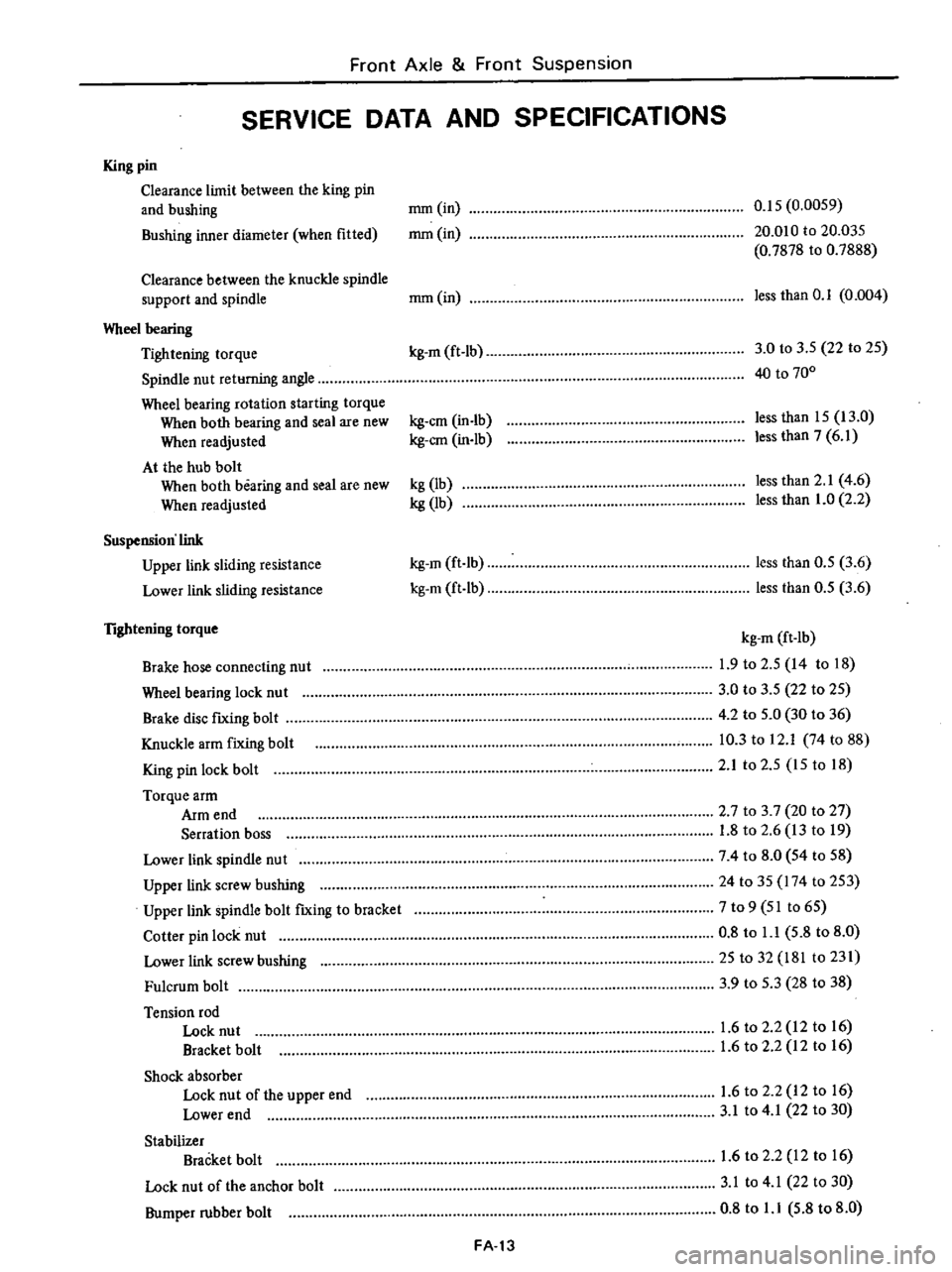
SERVICE
DATA
AND
SPECIFICATIONS
King
pin
Clearance
limit
between
the
king
pin
and
bushing
mm
in
0
15
0
0059
Bushing
inner
diameter
when
fitted
mm
in
20
010
to
20
035
0
7878
to
0
7888
Clearance
between
the
knuckle
spindle
support
and
spindle
mm
in
less
than
0
1
0
004
Wheel
bearing
Tightening
torque
kg
m
ft
Ib
3
0
to
3
S
22
to
2S
Spindle
nut
returning
angle
40
to
700
Wheel
bearing
rotation
starting
torque
When
both
bearing
and
seal
are
new
kg
em
in
Ib
less
than
IS
13
0
When
readjusted
kg
em
in
lb
less
than
7
6
1
At
the
hub
bolt
When
both
bearing
and
seal
are
new
kg
lb
less
than
2
1
4
6
When
readjusted
kg
lb
less
than
1
0
2
2
Suspension
link
Upper
link
sliding
resistance
kg
m
ft
Ib
less
than
O
S
3
6
Lower
link
sliding
resistance
kg
m
ft
lb
less
than
O
S
3
6
lightening
torque
kg
m
ft
Ib
Brake
hose
connecting
nut
1
9
to
2
S
14
to
18
Wheel
bearing
lock
nu
t
3
0
to
3
5
22
to
2S
Brake
disc
fIXing
bolt
4
2
to
S
O
30
to
36
Knuckle
arm
fixing
bolt
10
3
to
12
1
74
to
88
King
pin
lock
bolt
2
1
to
2
S
IS
to
18
Torque
arm
Arm
end
2
7
to
3
7
20
to
27
Serration
boss
1
8
to
2
6
13
to
19
Lower
link
spindle
nut
74
to
8
0
S4
to
58
Upper
link
screw
bushing
24
to
35
174
to
2S3
Upper
link
spindle
bolt
fIXing
to
bracket
7
to
9
51
to
6S
Cotter
pin
lock
nut
0
8
to
l
l
5
8
to
8
0
Lower
link
screw
bushing
25
to
32
181
to
231
Fulcrum
bolt
3
9
to
S
3
28
to
38
Tension
rod
Lock
nut
1
6
to
2
2
12
to
16
Bracket
bolt
1
6
to
2
2
12
to
16
Shock
absorber
Lock
nut
of
the
upper
end
1
6
to
2
2
12
to
16
Lower
end
3
1
to
4
1
22
to
30
Stabilizer
Bracket
bolt
1
6
to
2
2
12
to
16
Lock
nut
of
the
anchor
bolt
3
1
to
4
1
22
to
30
Bumper
rubber
bolt
0
8
to
l
l
5
8
to
8
0
FA
13
Page 364 of 537
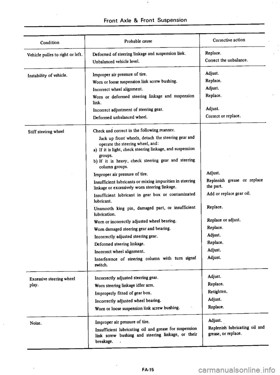
Condition
Vehicle
puBes
to
right
or
left
Instability
of
vehicle
Stiff
steeirng
wheel
Excessive
steering
wheel
play
Noise
Front
Axle
Front
Suspension
Probable
cause
Deformed
of
steering
linkage
and
suspension
link
Unbalanced
vehicle
level
Improper
air
pressure
of
tire
Worn
or
loose
suspension
link
screw
bushing
Incorrect
wheel
alignment
Worn
or
deformed
steering
linkage
and
suspension
link
Incorrect
adjustment
of
steering
gear
Deformed
unbalanced
wheel
Check
and
correct
in
the
following
manner
Jack
up
front
wheels
detach
the
steering
gear
and
operate
the
steering
wheel
and
a
If
it
is
light
check
steering
linkage
and
suspension
groups
b
If
it
is
heavy
check
steering
gear
and
steering
column
groups
Improper
air
pressure
of
tire
Insufficient
lubricants
or
mixing
impurities
in
steering
linkage
or
excessively
worn
steering
linkage
Insufficient
lubricant
in
gear
box
or
contaminated
lubricant
Unsmooth
king
pin
damaged
part
Or
insufficient
lubrication
Worn
or
incorrectly
adjusted
wheel
bearing
Worn
damaged
steering
gear
and
bearing
Incorrectly
adjusted
steering
gear
Deformed
steering
linkage
Incorrect
wheel
alignment
Interference
of
steering
column
with
turn
signal
switch
Incorrectly
adjusted
steering
gear
Worn
steering
linkage
idler
arm
Improperly
fitted
of
gear
box
Incorrectly
adjusted
wheel
bearing
Worn
or
loose
suspension
link
screw
bushing
Improper
air
pressure
of
tire
Insufficient
lubricating
oil
and
grease
for
suspension
link
screw
bushing
and
steering
linkage
or
their
breakage
FA
15
Corrective
action
Replace
Correct
the
unbalance
Adjust
Replace
Adjust
Replace
Adjust
Correct
or
replace
Adjust
Replenish
grease
or
replace
the
part
Add
or
replace
gear
oil
Replace
Replace
or
adjust
Replace
Adjust
Replace
Adjust
Adjust
Adjust
Replace
Retighten
Adjust
Replace
Adjust
Replenish
lubricating
oil
and
grease
or
replace
Page 383 of 537
REMOVAL
1
Removing
flare
nuts
on
both
ends
and
clips
effects
the
removal
of
brake
tube
and
brake
hose
2
Rear
brake
hose
can
be
removed
by
disconnecting
the
tube
and
then
turning
round
the
hose
Note
When
removing
brake
tubes
and
hoses
use
Flare
Nut
Torque
Wrench
GG943IOOOO
Never
use
an
OpeD
end
or
an
adjust
able
wrench
INSPECTION
1
Examine
all
hoses
for
swell
rubbing
marks
or
ozone
cracking
re
placing
those
found
with
any
of
above
badly
beyond
use
Also
inspect
end
fittings
and
be
sure
that
no
fluid
leak
through
staked
end
has
taken
place
replace
if
necessary
Hose
with
badly
rusted
fitting
should
also
be
replaced
with
a
new
one
2
Clean
all
tubes
to
remove
dust
and
dirt
with
isopropyl
alcohol
check
ing
for
collapse
wear
cracking
swell
or
rusting
Replace
if
foun
d
with
any
of
wove
Use
care
not
to
damage
brake
tubes
while
operation
Check
if
tubes
are
clamped
secure
ly
Mter
all
brake
lines
have
been
installed
retighten
aU
connections
if
necessary
to
assist
in
obtaining
correct
torque
In
retightening
at
front
wheel
cylinder
first
remove
hose
clamp
and
loosen
flare
nut
on
opposite
side
to
avoid
twisting
hose
Hold
pedal
as
far
downward
as
possible
80
kg
176
lb
or
more
examining
evidence
as
to
whether
fluid
is
leaking
through
brake
lines
or
con
nections
Leakage
in
any
manner
can
not
be
permitted
here
In
case
fluid
leaks
tightening
to
specified
torque
tighten
additionally
up
to
2
5
kg
m
J
8
ft
lb
Under
no
circumstances
should
not
be
tightened
over
2
5
kg
m
18
ft
Ib
torque
since
this
elongates
end
fitting
making
it
impossible
to
reuse
brake
tube
Under
no
circumstances
should
rear
brake
hose
and
3
way
connector
be
retightened
over
specified
torques
In
Brake
System
stead
replace
copper
washer
with
a
new
one
after
checking
for
sign
of
damage
on
seating
surface
Never
reuse
an
old
copper
washer
INSTALLATION
Brake
hose
Front
brake
hose
In
installing
brake
hose
first
jack
up
vehicle
to
take
off
the
weight
of
vehicle
from
wheels
so
that
suspension
is
in
rebound
Steering
wheel
should
also
be
kept
in
straight
ahead
position
To
connect
brake
line
first
connect
brake
hose
to
wheel
cylinder
with
the
specified
torque
Tightening
torque
1
7
to
2
0
kg
m
12
to
14
ft
Ib
Then
secure
brake
hose
to
the
bracket
with
lock
plate
so
as
not
to
twist
or
abnormally
bend
the
hose
Note
After
connecting
brake
hose
at
both
eiuIs
pay
keen
attention
not
to
twist
the
hose
when
additional
tightening
is
required
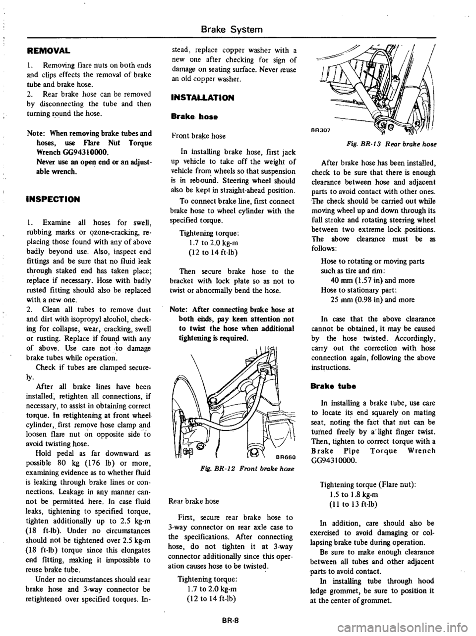
Fig
BR
12
Front
brake
hose
Rear
brake
hose
First
secure
rear
brake
hose
to
3
way
connector
on
rear
axle
case
to
the
specifications
Mter
connecting
hose
do
not
tighten
it
at
3
way
connector
additionally
since
this
oper
ation
causes
hose
to
be
twisted
Tightening
torque
I
7
to
2
0
kg
m
12
to
14
ft
Ib
BR
8
Fig
BR
13
Rear
brake
ho
e
After
brake
hose
has
been
installed
check
to
be
sure
that
there
is
enough
clearance
between
hose
and
adjacent
parts
to
avoid
contact
with
other
ones
The
check
should
be
carried
out
while
moving
wheel
up
and
down
through
its
full
stroke
and
rotating
steering
wheel
between
two
extreme
lock
positions
The
wow
clearance
must
be
as
follows
Hose
to
rotating
or
mOving
parts
such
as
tire
and
rim
40
mm
1
57
in
and
more
Hose
to
stationary
part
2S
mm
0
98
in
and
more
In
case
that
the
above
clearance
cannot
be
obtained
it
may
be
caused
by
the
hose
twisted
Accordingly
carry
out
the
correction
with
hose
connection
again
following
the
above
instructions
Brake
tube
In
installing
a
brake
tube
use
care
to
locate
its
end
squarely
on
mating
seat
noting
the
fact
that
nut
can
be
turned
freely
by
a
light
finger
twist
Then
tighten
to
correct
torque
with
a
Brake
Pipe
Torque
Wrench
GG943
10000
Tightening
torque
Flare
nut
1
5
to
1
8
kg
m
11
to
13
ft
Ib
In
addition
care
should
also
be
exercised
to
avoid
damaging
or
col
lapsing
brake
tube
during
operation
Be
sure
to
make
enough
clearance
between
all
tubes
and
other
adjacent
parts
to
avoid
contact
In
installing
tube
through
hood
ledge
grommet
be
sure
to
position
it
at
the
center
of
grommet
Page 384 of 537
After
connecting
brake
tube
be
sure
to
check
the
clearance
to
prevent
from
damage
The
clearance
at
the
following
portions
must
be
specified
distance
or
more
Tube
to
body
panel
and
frame
Over
5
mm
0
20
in
Tube
to
edge
of
each
panel
Over
10
mm
0
39
in
Tube
to
tube
Loop
pitch
OVer
5
mm
0
20
in
Between
front
tube
and
rear
tube
Over
9
mOl
0
35
in
Tube
to
moving
parts
Over
10
mm
0
39
in
Loop
tube
to
hood
ledge
panel
Over
10
mm
0
39
in
Notes
a
Brake
tubes
are
shaped
at
factory
to
secure
specified
clearance
and
may
not
require
reshaping
Discard
if
they
call
for
excessive
reshaping
b
In
reshaping
a
brake
tube
take
care
to
avoid
damaging
galvanization
or
collapsing
section
Mter
brake
lines
have
been
asssem
bled
check
to
make
sure
that
all
fittings
and
flare
nu
Is
ale
lightened
to
correct
torques
Tightenint
torque
Brake
tube
to
connector
I
Ston
kg
m
II
to
13
ft
Ib
Brake
tube
to
brake
hose
1
7
to
2
0
kg
m
12
to
14
ft
lb
Connector
and
clip
fixing
bolt
O
3S
to
O
4S
kg
m
2
5
to
3
3
ft
lb
3
way
connector
fixing
bolt
on
rear
axle
case
0
8
to
1
1
kg
m
6
to
8
ft
lb
N
L
S
V
DESCRIPTION
The
Nissan
Load
Sensing
Valve
N
L
S
V
serves
to
change
braking
power
of
the
rear
wheels
in
response
to
changes
in
the
load
and
fluid
pressure
improving
braking
stability
and
shortening
stopping
distances
Brake
System
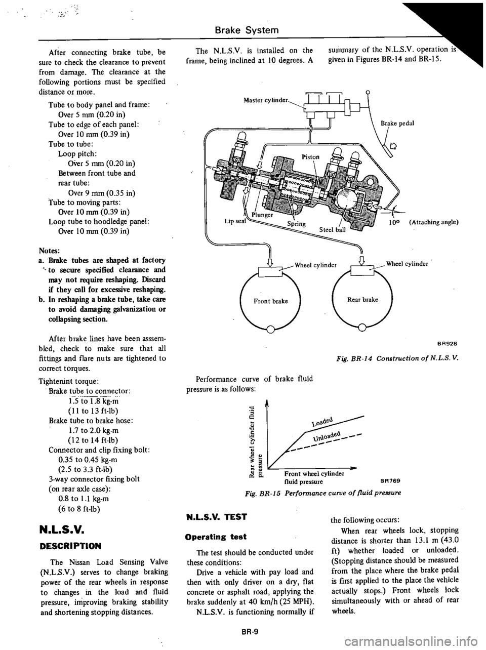
The
N
L
S
V
is
installed
on
the
frame
being
inclined
at
10
degrees
A
summary
of
the
N
L
S
v
operation
is
given
in
Figures
BR
14
and
BR
15
r
Master
cylinder
TI
II
I
y
1
J
I
l
Attaching
angle
D
Wheel
cylinder
BR928
Fig
BR
14
Construction
of
N
L
S
V
Performance
curve
of
brake
fluid
pressure
is
as
follows
0
S
c
A
0
C
o
l
0
oadea
U1U
Front
wheel
cylinder
fluid
pressure
BR769
Perfonnance
curve
of
fluid
pressure
Fig
BR
15
N
L
S
V
TEST
the
following
occurs
When
rear
wheels
lock
stopping
distance
is
shorter
than
13
1
m
43
0
ft
whether
loaded
or
unloaded
Stopping
distance
should
be
measured
from
the
place
where
the
brake
pedal
is
first
applied
to
the
place
the
vehicle
actually
stops
Front
wheels
lock
simultaneously
with
or
ahead
of
rear
wheels
Operating
test
The
test
should
be
conducted
under
these
conditions
Drive
a
vehicle
with
pay
load
and
then
with
only
driver
on
a
dry
flat
concrete
or
asphalt
road
applying
the
brake
suddenly
at
40
km
h
25
MPH
N
L
S
V
is
functioning
normally
if
BR
9