spark plugs replace DODGE NEON 1999 Service User Guide
[x] Cancel search | Manufacturer: DODGE, Model Year: 1999, Model line: NEON, Model: DODGE NEON 1999Pages: 1200, PDF Size: 35.29 MB
Page 724 of 1200

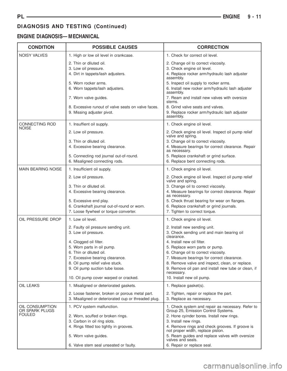
ENGINE DIAGNOSISÐMECHANICAL
CONDITION POSSIBLE CAUSES CORRECTION
NOISY VALVES 1. High or low oil level in crankcase. 1. Check for correct oil level.
2. Thin or diluted oil. 2. Change oil to correct viscosity.
3. Low oil pressure. 3. Check engine oil level.
4. Dirt in tappets/lash adjusters. 4. Replace rocker arm/hydraulic lash adjuster
assembly.
5. Worn rocker arms. 5. Inspect oil supply to rocker arms.
6. Worn tappets/lash adjusters. 6. Install new rocker arm/hydraulic lash adjuster
assembly.
7. Worn valve guides. 7. Ream and install new valves with oversize
stems.
8. Excessive runout of valve seats on valve faces. 8. Grind valve seats and valves.
9. Missing adjuster pivot. 9. Replace rocker arm/hydraulic lash adjuster
assembly.
CONNECTING ROD
NOISE1. Insuffient oil supply. 1. Check engine oil level.
2. Low oil pressure. 2. Check engine oil level. Inspect oil pump relief
valve and spring.
3. Thin or diluted oil. 3. Change oil to correct viscosity.
4. Excessive bearing clearance. 4. Measure bearings for correct clearance. Repair
as necessary.
5. Connecting rod journal out-of-round. 5. Replace crankshaft or grind surface.
6. Misaligned connecting rods. 6. Replace bent connecting rods.
MAIN BEARING NOISE 1. Insufficient oil supply. 1. Check engine oil level.
2. Low oil pressure. 2. Check engine oil level. Inspect oil pump relief
valve and spring.
3. Thin or diluted oil. 3. Change oil to correct viscosity.
4. Excessive bearing clearance. 4. Measure bearings for correct clearance. Repair
as necessary.
5. Excessive end play. 5. Check thrust bearing for wear on flanges.
6. Crankshaft journal out-of-round or worn. 6. Replace crankshaft or grind journals.
7. Loose flywheel or torque converter. 7. Tighten to correct torque.
OIL PRESSURE DROP 1. Low oil level. 1. Check engine oil level.
2. Faulty oil pressure sending unit. 2. Install new sending unit.
3. Low oil pressure. 3. Check sending unit and main bearing oil
clearance.
4. Clogged oil filter. 4. Install new oil filter.
5. Worn parts in oil pump. 5. Replace worn parts or pump.
6. Thin or diluted oil. 6. Change oil to correct viscosity.
7. Excessive bearing clearance. 7. Measure bearings for correct clearance.
8. Oil pump relief valve stuck. 8. Remove valve and inspect, clean, or replace.
9. Oil pump suction tube loose. 9. Remove oil pan and install new tube or clean, if
necessary.
10. Oil pump cover warped or cracked. 10. Install new oil pump.
OIL LEAKS 1. Misaligned or deteriorated gaskets. 1. Replace gasket(s).
2. Loose fastener, broken or porous metal part. 2. Tighten, repair or replace the part.
3. Misaligned or deteriorated cup or threaded plug. 3. Replace as necessary.
OIL CONSUMPTION
OR SPARK PLUGS
FOULED1. PCV system malfunction. 1. Check system and repair as necessary. Refer to
Group 25, Emission Control Systems.
2. Worn, scuffed or broken rings. 2. Hone cyinder bores. Install new rings.
3. Carbon in oil ring slots. 3. Install new rings.
4. Rings fitted too tightly in grooves. 4. Remove rings and check grooves. If groove is
not proper width, replace piston.
5. Worn valve guides. 5. Ream guides and replace valves with oversize
valves and seals.
6. Valve stem seal unseated or faulty. 6. Repair or replace seal.
PLENGINE 9 - 11
DIAGNOSIS AND TESTING (Continued)
Page 817 of 1200

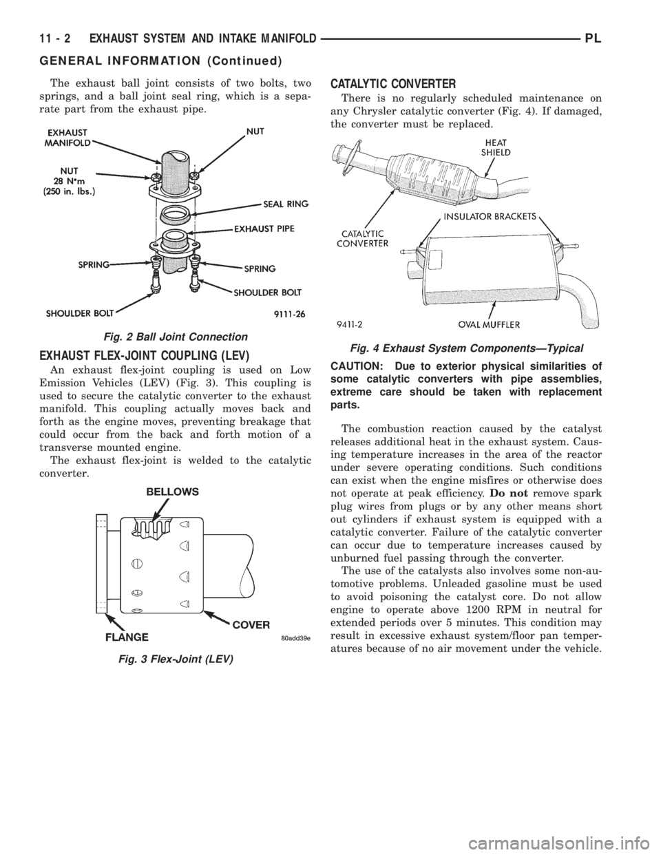
The exhaust ball joint consists of two bolts, two
springs, and a ball joint seal ring, which is a sepa-
rate part from the exhaust pipe.
EXHAUST FLEX-JOINT COUPLING (LEV)
An exhaust flex-joint coupling is used on Low
Emission Vehicles (LEV) (Fig. 3). This coupling is
used to secure the catalytic converter to the exhaust
manifold. This coupling actually moves back and
forth as the engine moves, preventing breakage that
could occur from the back and forth motion of a
transverse mounted engine.
The exhaust flex-joint is welded to the catalytic
converter.
CATALYTIC CONVERTER
There is no regularly scheduled maintenance on
any Chrysler catalytic converter (Fig. 4). If damaged,
the converter must be replaced.
CAUTION: Due to exterior physical similarities of
some catalytic converters with pipe assemblies,
extreme care should be taken with replacement
parts.
The combustion reaction caused by the catalyst
releases additional heat in the exhaust system. Caus-
ing temperature increases in the area of the reactor
under severe operating conditions. Such conditions
can exist when the engine misfires or otherwise does
not operate at peak efficiency.Do notremove spark
plug wires from plugs or by any other means short
out cylinders if exhaust system is equipped with a
catalytic converter. Failure of the catalytic converter
can occur due to temperature increases caused by
unburned fuel passing through the converter.
The use of the catalysts also involves some non-au-
tomotive problems. Unleaded gasoline must be used
to avoid poisoning the catalyst core. Do not allow
engine to operate above 1200 RPM in neutral for
extended periods over 5 minutes. This condition may
result in excessive exhaust system/floor pan temper-
atures because of no air movement under the vehicle.
Fig. 2 Ball Joint Connection
Fig. 3 Flex-Joint (LEV)
Fig. 4 Exhaust System ComponentsÐTypical
11 - 2 EXHAUST SYSTEM AND INTAKE MANIFOLDPL
GENERAL INFORMATION (Continued)
Page 878 of 1200

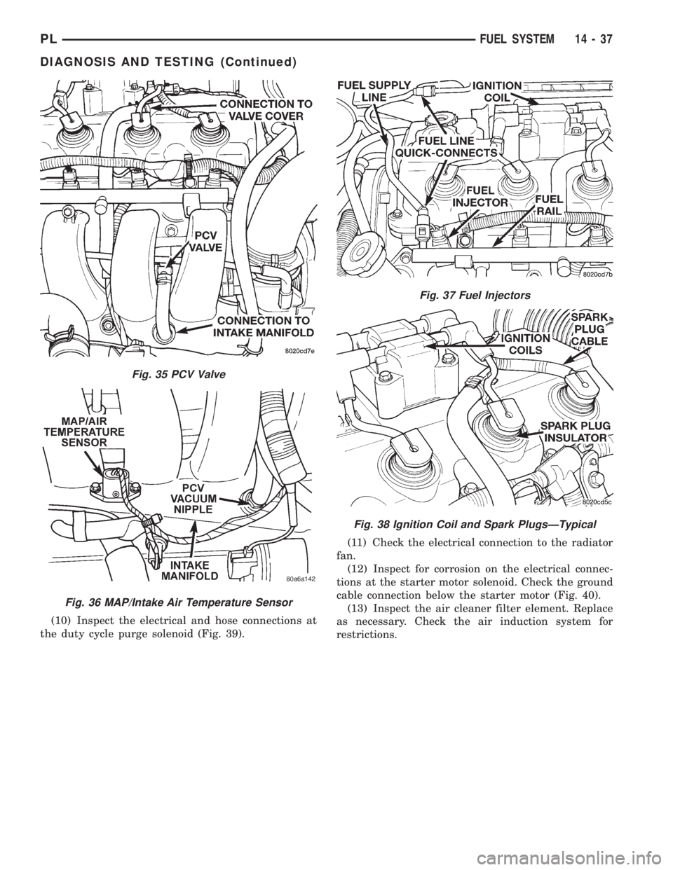
(10) Inspect the electrical and hose connections at
the duty cycle purge solenoid (Fig. 39).(11) Check the electrical connection to the radiator
fan.
(12) Inspect for corrosion on the electrical connec-
tions at the starter motor solenoid. Check the ground
cable connection below the starter motor (Fig. 40).
(13) Inspect the air cleaner filter element. Replace
as necessary. Check the air induction system for
restrictions.
Fig. 35 PCV Valve
Fig. 36 MAP/Intake Air Temperature Sensor
Fig. 37 Fuel Injectors
Fig. 38 Ignition Coil and Spark PlugsÐTypical
PLFUEL SYSTEM 14 - 37
DIAGNOSIS AND TESTING (Continued)