DODGE NEON 1999 Service Repair Manual
Manufacturer: DODGE, Model Year: 1999, Model line: NEON, Model: DODGE NEON 1999Pages: 1200, PDF Size: 35.29 MB
Page 291 of 1200
RADIO
REMOVAL
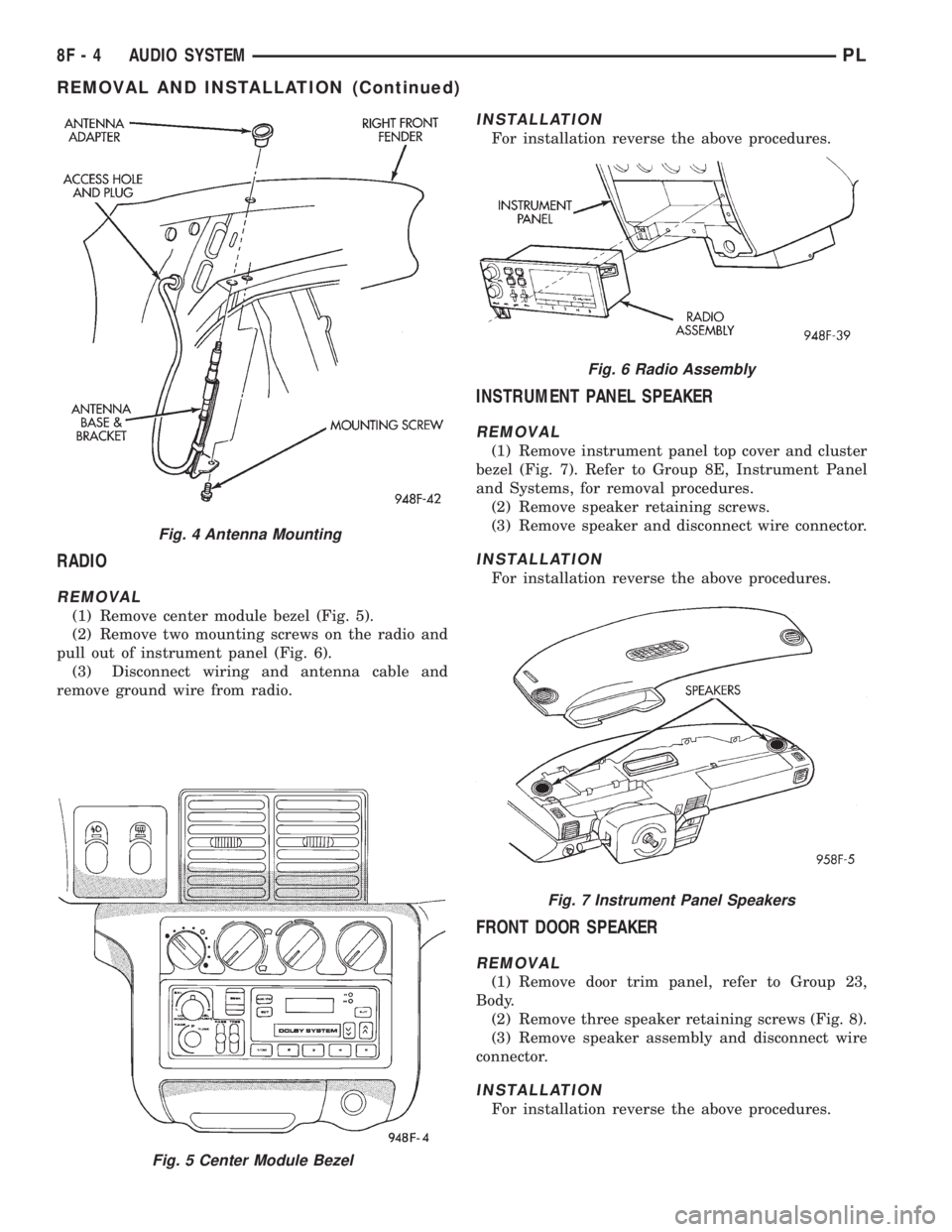
(1) Remove center module bezel (Fig. 5).
(2) Remove two mounting screws on the radio and
pull out of instrument panel (Fig. 6).
(3) Disconnect wiring and antenna cable and
remove ground wire from radio.
INSTALLATION
For installation reverse the above procedures.
INSTRUMENT PANEL SPEAKER
REMOVAL
(1) Remove instrument panel top cover and cluster
bezel (Fig. 7). Refer to Group 8E, Instrument Panel
and Systems, for removal procedures.
(2) Remove speaker retaining screws.
(3) Remove speaker and disconnect wire connector.
INSTALLATION
For installation reverse the above procedures.
FRONT DOOR SPEAKER
REMOVAL
(1) Remove door trim panel, refer to Group 23,
Body.
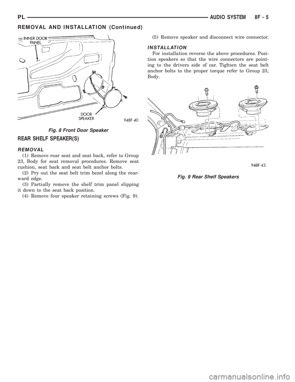
(2) Remove three speaker retaining screws (Fig. 8).
(3) Remove speaker assembly and disconnect wire
connector.
INSTALLATION
For installation reverse the above procedures.
Fig. 5 Center Module Bezel
Fig. 4 Antenna Mounting
Fig. 6 Radio Assembly
Fig. 7 Instrument Panel Speakers
8F - 4 AUDIO SYSTEMPL
REMOVAL AND INSTALLATION (Continued)
Page 292 of 1200
REAR SHELF SPEAKER(S)
REMOVAL
(1) Remove rear seat and seat back, refer to Group
23, Body for seat removal procedures. Remove seat
cushion, seat back and seat belt anchor bolts.
(2) Pry out the seat belt trim bezel along the rear-
ward edge.
(3) Partially remove the shelf trim panel slipping
it down to the seat back position.
(4) Remove four speaker retaining screws (Fig. 9).(5) Remove speaker and disconnect wire connector.
INSTALLATION
For installation reverse the above procedures. Posi-
tion speakers so that the wire connectors are point-
ing to the drivers side of car. Tighten the seat belt
anchor bolts to the proper torque refer to Group 23,
Body.
Fig. 8 Front Door Speaker
Fig. 9 Rear Shelf Speakers
PLAUDIO SYSTEM 8F - 5
REMOVAL AND INSTALLATION (Continued)
Page 293 of 1200

Page 294 of 1200
HORNS
CONTENTS
page page
DESCRIPTION AND OPERATION
INTRODUCTION......................... 1
DIAGNOSIS AND TESTING
HORN RELAY........................... 2
HORN SWITCH.......................... 2
HORN................................. 1SYSTEM TEST.......................... 2
REMOVAL AND INSTALLATION
HORN RELAY........................... 4
HORN SWITCHES........................ 4
HORN................................. 4
DESCRIPTION AND OPERATION
INTRODUCTION
WARNING: ON VEHICLES EQUIPPED WITH AIR-
BAG, SEE GROUP 8M, RESTRAINT SYSTEMS FOR
STEERING WHEEL OR COLUMN REMOVAL PROCE-
DURES.
The horn circuit consists of a horn switch, horn
relay, and horn. The horn circuit feed is from the fuse
to the horn relay in the Power Distribution Center
(PDC). The PDC is mounted on the battery tray.
When the horn switch is depressed, it completes the
ground circuit. The horn relay coil closes contacts
and allows current to flow to the horn. The horn is
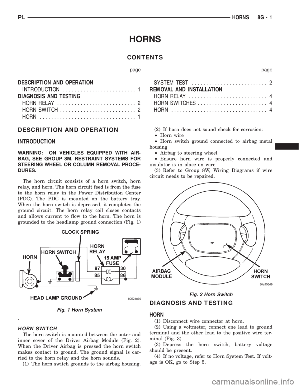
grounded to the headlamp ground connection (Fig. 1)
.
HORN SWITCH
The horn switch is mounted between the outer and
inner cover of the Driver Airbag Module (Fig. 2).
When the Driver Airbag is pressed the horn switch
makes contact to ground. The ground signal is car-
ried to the horn relay and the horn sounds.
(1) The horn switch grounds to the airbag housing.(2) If horn does not sound check for corrosion:
²Horn wire
²Horn switch ground connected to airbag metal
housing
²Airbag to steering wheel
²Ensure horn wire is properly connected and
insulator is in place on wire
(3) Refer to Group 8W, Wiring Diagrams if wire
circuit needs to be repaired.
DIAGNOSIS AND TESTING
HORN
(1) Disconnect wire connector at horn.
(2) Using a voltmeter, connect one lead to ground
terminal and the other lead to the positive wire ter-
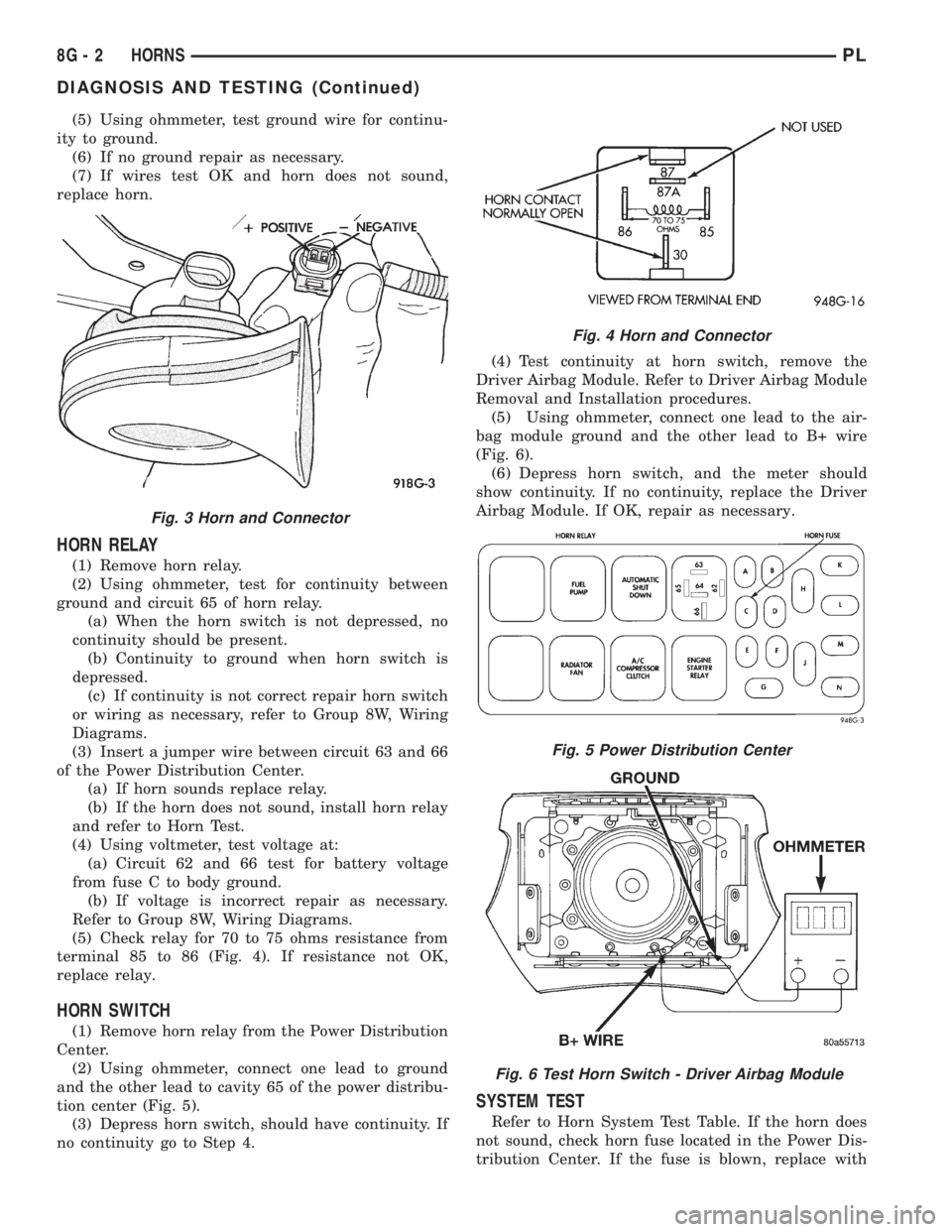
minal (Fig. 3).
(3) Depress the horn switch, battery voltage
should be present.
(4) If no voltage, refer to Horn System Test. If volt-
age is OK, go to Step 5.
Fig. 1 Horn System
Fig. 2 Horn Switch
PLHORNS 8G - 1
Page 295 of 1200
(5) Using ohmmeter, test ground wire for continu-
ity to ground.
(6) If no ground repair as necessary.
(7) If wires test OK and horn does not sound,
replace horn.
HORN RELAY
(1) Remove horn relay.
(2) Using ohmmeter, test for continuity between
ground and circuit 65 of horn relay.
(a) When the horn switch is not depressed, no
continuity should be present.
(b) Continuity to ground when horn switch is
depressed.
(c) If continuity is not correct repair horn switch
or wiring as necessary, refer to Group 8W, Wiring
Diagrams.
(3) Insert a jumper wire between circuit 63 and 66
of the Power Distribution Center.
(a) If horn sounds replace relay.
(b) If the horn does not sound, install horn relay
and refer to Horn Test.
(4) Using voltmeter, test voltage at:
(a) Circuit 62 and 66 test for battery voltage
from fuse C to body ground.
(b) If voltage is incorrect repair as necessary.
Refer to Group 8W, Wiring Diagrams.
(5) Check relay for 70 to 75 ohms resistance from
terminal 85 to 86 (Fig. 4). If resistance not OK,
replace relay.
HORN SWITCH
(1) Remove horn relay from the Power Distribution
Center.
(2) Using ohmmeter, connect one lead to ground
and the other lead to cavity 65 of the power distribu-
tion center (Fig. 5).
(3) Depress horn switch, should have continuity. If
no continuity go to Step 4.(4) Test continuity at horn switch, remove the
Driver Airbag Module. Refer to Driver Airbag Module
Removal and Installation procedures.
(5) Using ohmmeter, connect one lead to the air-
bag module ground and the other lead to B+ wire
(Fig. 6).
(6) Depress horn switch, and the meter should
show continuity. If no continuity, replace the Driver
Airbag Module. If OK, repair as necessary.
SYSTEM TEST
Refer to Horn System Test Table. If the horn does
not sound, check horn fuse located in the Power Dis-
tribution Center. If the fuse is blown, replace with
Fig. 3 Horn and Connector
Fig. 4 Horn and Connector
Fig. 5 Power Distribution Center
Fig. 6 Test Horn Switch - Driver Airbag Module
8G - 2 HORNSPL
DIAGNOSIS AND TESTING (Continued)
Page 296 of 1200
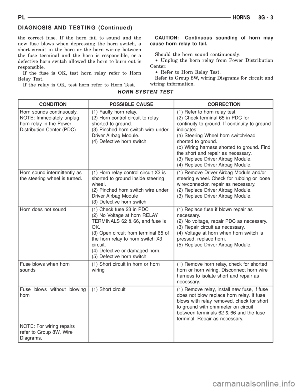
the correct fuse. If the horn fail to sound and the
new fuse blows when depressing the horn switch, a
short circuit in the horn or the horn wiring between
the fuse terminal and the horn is responsible, or a
defective horn switch allowed the horn to burn out is
responsible.
If the fuse is OK, test horn relay refer to Horn
Relay Test.
If the relay is OK, test horn refer to Horn Test.CAUTION: Continuous sounding of horn may
cause horn relay to fail.
Should the horn sound continuously:
²Unplug the horn relay from Power Distribution
Center.
²Refer to Horn Relay Test.
Refer to Group 8W, wiring Disgrams for circuit and
wiring information.
HORN SYSTEM TEST
CONDITION POSSIBLE CAUSE CORRECTION
Horn sounds continuously.
NOTE: Immediately unplug
horn relay in the Power
Distribution Center (PDC)(1) Faulty horn relay.
(2) Horn control circuit to relay
shorted to ground.
(3) Pinched horn switch wire under
Driver Airbag Module.
(4) Defective horn switch(1) Refer to horn relay test.
(2) Check terminal 65 in PDC for
continuity to ground. If continuity to ground
indicates:
(a) Steering Wheel horn switch/lead
shorted to ground.
(b) Wiring harness shorted to ground. Find
the short and repair as necessary.
(3) Replace Driver Airbag Module.
(4) Replace Driver Airbag Module.
Horn sound intermittently as
the steering wheel is turned.(1) Horn relay control circuit X3 is
shorted to ground inside steering
wheel.
(2) Pinched horn switch wire under
Driver Airbag Module
(3) Defective horn switch(1) Remove Driver Airbag Module and/or
steering wheel. Check for rubbing or loose
wire/connector, repair as necessary.
(2) Replace Driver Airbag Module.
(3) Replace Driver Airbag Module.
Horn does not sound (1) Check fuse 23 in PDC
(2) No Voltage at horn RELAY
TERMINALS 62 & 66, and fuse is
OK.
(3) Open circuit from terminal 65 of
the horn relay to horn switch X3
circuit.
(4) Defective or damaged horn.
(5) Defective horn switch(1) Replace fuse if blown repair as
necessary.
(2) No voltage, repair PDC as necessary.
(3) Repair circuit as necessary.
(4) Voltage at horn when horn switch is
pressed, replace horn.
(5) Replace Driver Airbag Module.
Fuse blows when horn
sounds(1) Short circuit in horn or horn
wiring(1) Remove horn relay, check for shorted
horn or horn wiring. Disconnect horn wire
harness to isolate short and repair as
necessary.
Fuse blows without blowing
horn(1) Short circuit (1) Remove relay, install new fuse, if fuse
does not blow replace horn relay. If fuse
blows with relay removed, check for short
to ground with ohmmeter on circuit
between terminals 62 & 66 and the fuse
terminal. Repair as necessary.
NOTE: For wiring repairs
refer to Group 8W, Wire
Diagrams.
PLHORNS 8G - 3
DIAGNOSIS AND TESTING (Continued)
Page 297 of 1200
REMOVAL AND INSTALLATION
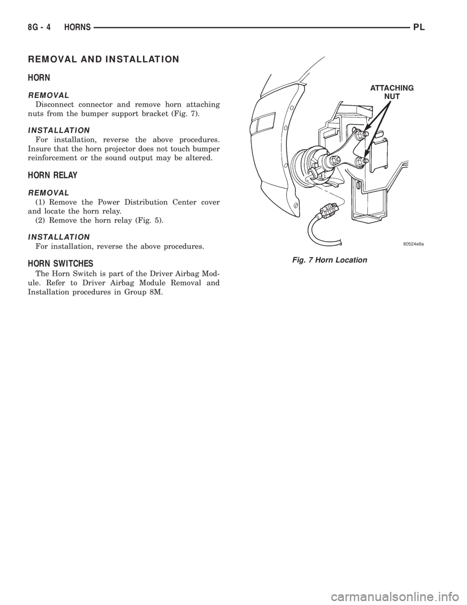
HORN
REMOVAL
Disconnect connector and remove horn attaching
nuts from the bumper support bracket (Fig. 7).
INSTALLATION
For installation, reverse the above procedures.
Insure that the horn projector does not touch bumper
reinforcement or the sound output may be altered.
HORN RELAY
REMOVAL
(1) Remove the Power Distribution Center cover
and locate the horn relay.
(2) Remove the horn relay (Fig. 5).
INSTALLATION
For installation, reverse the above procedures.
HORN SWITCHES
The Horn Switch is part of the Driver Airbag Mod-
ule. Refer to Driver Airbag Module Removal and
Installation procedures in Group 8M.
Fig. 7 Horn Location
8G - 4 HORNSPL
Page 298 of 1200
VEHICLE SPEED CONTROL SYSTEM
CONTENTS
page page
GENERAL INFORMATION
INTRODUCTION......................... 1
DESCRIPTION AND OPERATION
POWERTRAIN CONTROL MODULE.......... 3
SERVO CABLE.......................... 3
SPEED CONTROL SERVO.................. 1
SPEED CONTROL SWITCHES.............. 2
STOP LAMP SWITCH..................... 3
VACUUM RESERVOIR.................... 3
VEHICLE SPEED AND DISTANCE............ 3
DIAGNOSIS AND TESTING
CHECKING FOR DIAGNOSTIC CODES........ 4
ELECTRICAL TESTS AT POWERTRAIN
CONTROL MODULE..................... 7
OVERSHOOT/UNDERSHOOT FOLLOWING
SPEED CONTROL SET................... 6ROAD TEST............................ 3
SERVO VACUUM TEST.................... 6
SPEED CONTROL ELECTRICAL TEST........ 4
SPEED CONTROL SWITCH TEST............ 6
STOP LAMP SWITCH TEST................ 6
VACUUM SUPPLY TEST................... 8
VEHICLE SPEED SENSOR................. 8
REMOVAL AND INSTALLATION
POWERTRAIN CONTROL MODULE......... 10
SPEED CONTROL SERVO CABLE............ 9
SPEED CONTROL SERVO.................. 8
SPEED CONTROL SWITCH................. 8
STOP LAMP SWITCH.................... 8
VACUUM RESERVOIR................... 10
VEHICLE SPEED SENSOR................ 10
GENERAL INFORMATION
INTRODUCTION
The speed control system is electronically con-
trolled and vacuum operated. The electronic control
is integrated into the powertrain control module
which is located in the engine compartment. The con-
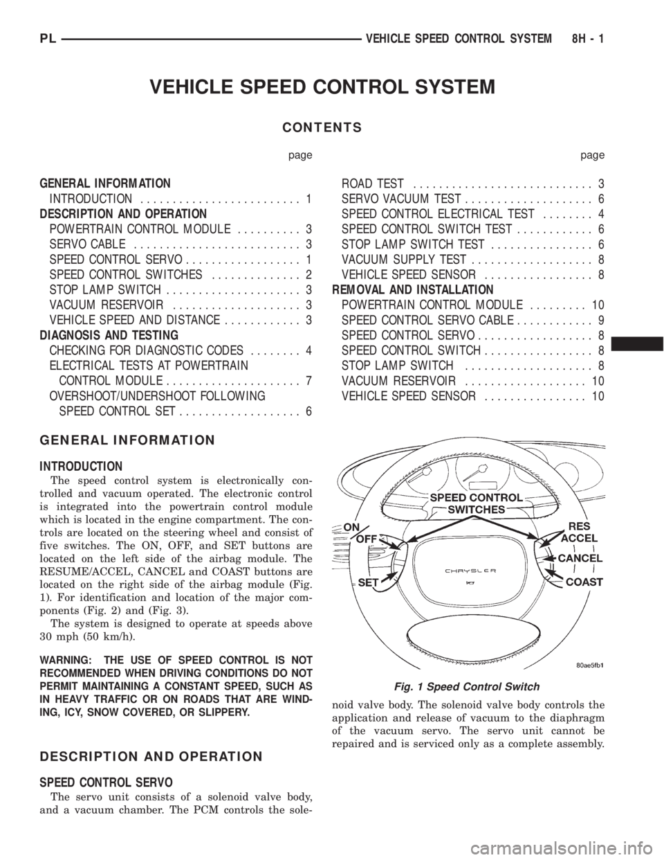
trols are located on the steering wheel and consist of
five switches. The ON, OFF, and SET buttons are
located on the left side of the airbag module. The
RESUME/ACCEL, CANCEL and COAST buttons are
located on the right side of the airbag module (Fig.
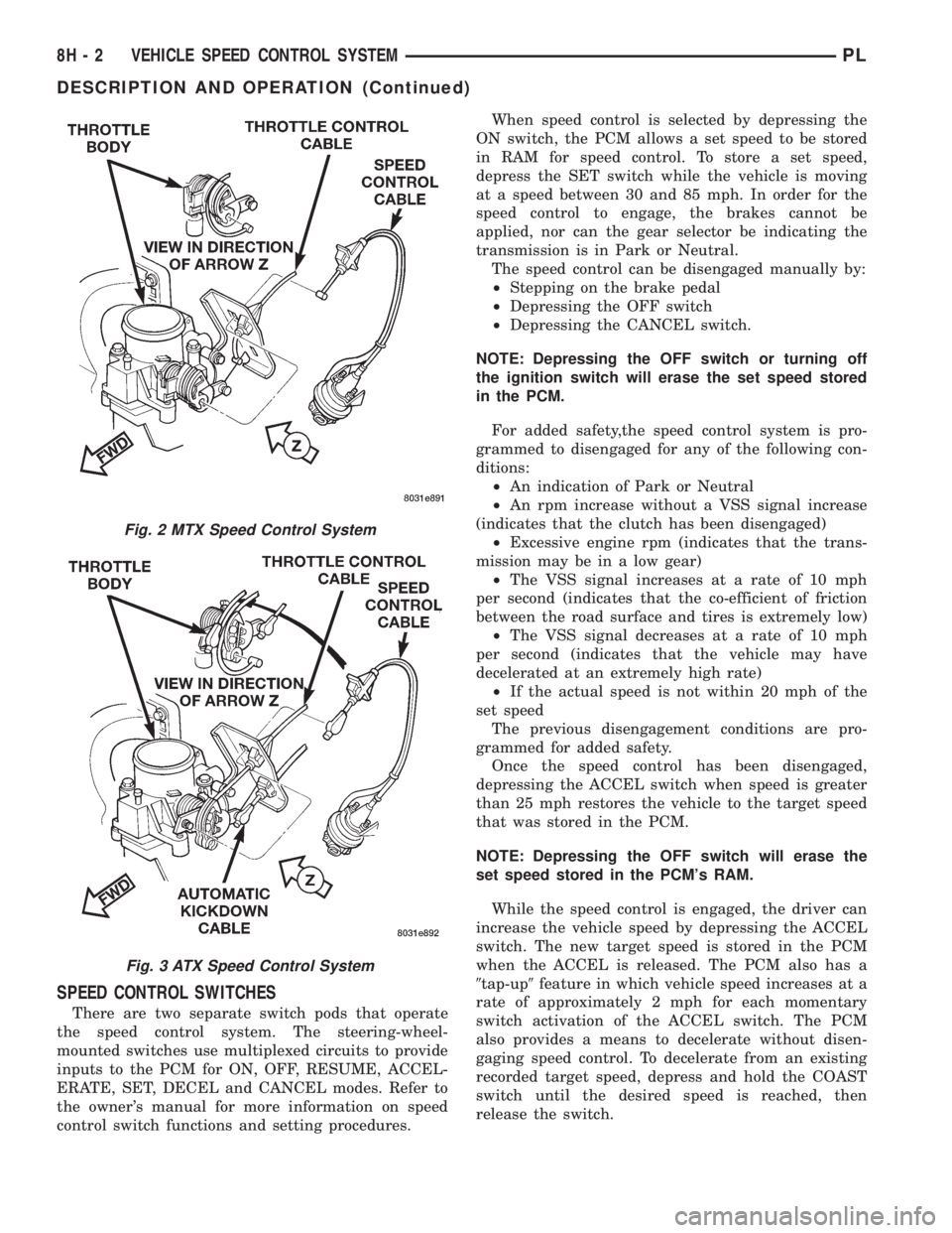
1). For identification and location of the major com-
ponents (Fig. 2) and (Fig. 3).
The system is designed to operate at speeds above
30 mph (50 km/h).
WARNING: THE USE OF SPEED CONTROL IS NOT
RECOMMENDED WHEN DRIVING CONDITIONS DO NOT
PERMIT MAINTAINING A CONSTANT SPEED, SUCH AS
IN HEAVY TRAFFIC OR ON ROADS THAT ARE WIND-
ING, ICY, SNOW COVERED, OR SLIPPERY.
DESCRIPTION AND OPERATION
SPEED CONTROL SERVO
The servo unit consists of a solenoid valve body,
and a vacuum chamber. The PCM controls the sole-noid valve body. The solenoid valve body controls the
application and release of vacuum to the diaphragm
of the vacuum servo. The servo unit cannot be
repaired and is serviced only as a complete assembly.
Fig. 1 Speed Control Switch
PLVEHICLE SPEED CONTROL SYSTEM 8H - 1
Page 299 of 1200
SPEED CONTROL SWITCHES
There are two separate switch pods that operate
the speed control system. The steering-wheel-
mounted switches use multiplexed circuits to provide
inputs to the PCM for ON, OFF, RESUME, ACCEL-
ERATE, SET, DECEL and CANCEL modes. Refer to
the owner's manual for more information on speed
control switch functions and setting procedures.When speed control is selected by depressing the
ON switch, the PCM allows a set speed to be stored
in RAM for speed control. To store a set speed,
depress the SET switch while the vehicle is moving
at a speed between 30 and 85 mph. In order for the
speed control to engage, the brakes cannot be
applied, nor can the gear selector be indicating the
transmission is in Park or Neutral.
The speed control can be disengaged manually by:
²Stepping on the brake pedal
²Depressing the OFF switch
²Depressing the CANCEL switch.
NOTE: Depressing the OFF switch or turning off
the ignition switch will erase the set speed stored
in the PCM.
For added safety,the speed control system is pro-
grammed to disengaged for any of the following con-
ditions:
²An indication of Park or Neutral
²An rpm increase without a VSS signal increase
(indicates that the clutch has been disengaged)
²Excessive engine rpm (indicates that the trans-
mission may be in a low gear)
²The VSS signal increases at a rate of 10 mph
per second (indicates that the co-efficient of friction
between the road surface and tires is extremely low)
²The VSS signal decreases at a rate of 10 mph
per second (indicates that the vehicle may have
decelerated at an extremely high rate)
²If the actual speed is not within 20 mph of the
set speed
The previous disengagement conditions are pro-
grammed for added safety.
Once the speed control has been disengaged,
depressing the ACCEL switch when speed is greater
than 25 mph restores the vehicle to the target speed
that was stored in the PCM.
NOTE: Depressing the OFF switch will erase the
set speed stored in the PCM's RAM.
While the speed control is engaged, the driver can
increase the vehicle speed by depressing the ACCEL
switch. The new target speed is stored in the PCM
when the ACCEL is released. The PCM also has a
9tap-up9feature in which vehicle speed increases at a
rate of approximately 2 mph for each momentary
switch activation of the ACCEL switch. The PCM
also provides a means to decelerate without disen-
gaging speed control. To decelerate from an existing
recorded target speed, depress and hold the COAST
switch until the desired speed is reached, then
release the switch.
Fig. 2 MTX Speed Control System
Fig. 3 ATX Speed Control System
8H - 2 VEHICLE SPEED CONTROL SYSTEMPL
DESCRIPTION AND OPERATION (Continued)
Page 300 of 1200
The individual switches cannot be repaired. If one
switch fails, the entire switch module must be
replaced.
STOP LAMP SWITCH
Vehicles equipped with the speed control option use
a dual function stop lamp switch. The switch is
mounted on the brake pedal mounting bracket under
the instrument panel. The PCM monitors the state of
the dual function stop lamp switch. Refer to Group 5,
Brakes for more information on stop lamp switch ser-
vice and adjustment procedures.
SERVO CABLE
The speed control servo cable is connected between
the speed control vacuum servo diaphragm and the
throttle body control linkage. This cable causes the
throttle control linkage to open or close the throttle
valve in response to movement of the vacuum servo
diaphragm.
POWERTRAIN CONTROL MODULE
The speed control electronic control circuitry is
integrated into the Powertrain Control Module
(PCM). The PCM is located in the engine compart-
ment. The PCM speed control functions are moni-
tored by the On-Board Diagnostics (OBD). All OBD-
sensed systems are monitored by the PCM. Each
monitored circuit is assigned a Diagnostic Trouble
Code (DTC). The PCM will store a DTC in electronic
memory for any failure it detects. See On-Board
Diagnostic Tests in this group for more information.
The PCM cannot be repaired and must be replaced if
faulty.
USE THE DRB SCAN TOOL TO REPROGRAM
THE NEW PCM WITH THE VEHICLES ORIGI-
NAL IDENTIFICATION NUMBER (VIN) AND
THE ORIGINAL VEHICLES MILEAGE. IF THIS
STEP IS NOT DONE A DIAGNOSTIC TROUBLE
CODE (DTC) MAY BE SET.
VACUUM RESERVOIR
The reservoir contains a one-way check valve to
trap engine vacuum in the reservoir. When engine
vacuum drops, as in climbing a grade while driving,
the reservoir supplies the vacuum needed to main-
tain proper speed control operation. The vacuum res-
ervoir cannot be repaired and must be replaced if
faulty.
VEHICLE SPEED AND DISTANCE
The 4 speed automatic Transmission Control Mod-
ule (TCM) supplies the speed input to the PCM. The
PCM determines acceleration rates. The speed con-
trol software in the PCM uses vehicle speed and
acceleration to control to the set speed.Vehicles with a 3 speed automatic or manual trans-
mission have a vehicle speed sensor (VSS) mounted
to an adapter near the transmission output shaft.
The sensor is driven through the adapter by a speed-
ometer pinion gear. The VSS pulse signal is moni-
tored by the PCM to determine vehicle speed and to
maintain speed control set speed. Refer to the appro-
priate Powertrain Diagnostic Procedures manual for
diagnosis and testing of this component. Refer to
group 14, Fuel System for Removal/Installation
DIAGNOSIS AND TESTING
ROAD TEST
Perform a vehicle road test to verify reports of
speed control system malfunction. The road test
should include attention to the speedometer. Speed-
ometer operation should be smooth and without flut-
ter at all speeds.
Flutter in the speedometer indicates a problem
which might cause surging in the speed control sys-
tem. The cause of any speedometer problems should
be corrected before proceeding. Refer to Group 8E,
Instrument Panel and Gauges for speedometer diag-
nosis.
If a road test verifies a surge following a set and
the speedometer operates properly see ªOvershoot/
Undershoot on speed control setº.
If a road test verifies an inoperative system, and
the speedometer operates properly, check for:
²A Diagnostic Trouble Code (DTC). If a DTC
exists, conduct tests per the Powertrain Diagnostic
Procedures service manual.
²A misadjusted brake (stop) lamp switch. This
could also cause an intermittent problem.
²Loose or corroded electrical connections at the
servo. Corrosion should be removed from electrical
terminals and a light coating of Mopar Multipurpose
Grease, or equivalent, applied.
²Leaking vacuum reservoir.
²Loose or leaking vacuum hoses or connections.
²Defective one-way vacuum check valve.
²Secure attachment at both ends of the speed
control servo cable.
²Smooth operation of throttle linkage and throttle
body air valve.
²Conduct electrical test at PCM.
²Failed speed control servo. Do the servo vacuum
test.
CAUTION: When test probing for voltage or conti-
nuity at electrical connectors, care must be taken
not to damage connector, terminals or seals. If
these components are damaged, intermittent or
complete system failure may occur.
PLVEHICLE SPEED CONTROL SYSTEM 8H - 3
DESCRIPTION AND OPERATION (Continued)