DODGE NEON 1999 Service Repair Manual
Manufacturer: DODGE, Model Year: 1999, Model line: NEON, Model: DODGE NEON 1999Pages: 1200, PDF Size: 35.29 MB
Page 301 of 1200
CHECKING FOR DIAGNOSTIC CODES
When trying to verify a speed control system elec-
tronic malfunction: Connect a DRB scan tool if avail-
able to the data link connector. The connector is
located at left side of the steering column, and at
lower edge of the panel.
(1) A speed control malfunction may occur without
a diagnostic code being indicated.
Refer to Group 25, for further information and use-
age of the DRB scan tool and a more complete list of
Diagnostic Trouble Code.
SPEED CONTROL SLOWS DOWN BY ITSELF
Test vehicle speed sensor, refer to group 8E. If sen-
sor fails replace sensor, if it passes perform the fol-
lowing test:
(1) Perform the speed control switch test on the
DECEL switch, if it fails replace switch.
(2) If the switch passes, conduct the vacuum sup-
ply test.
(3) If it passes, conduct the servo vacuum test. If it
fails replace servo.
(4) If continuity, replace the PCM.
SPEED CONTROL ELECTRICAL TEST
Electronic speed control systems may be tested
using two different methods. One involves use of aDRB. If this test method is desired, refer to the Pow-
ertrain Diagnostic Test Procedures for charging and
speed control system manual.
The other test method uses a volt/ohm meter. The
volt/ohm meter method is described in the following
tests.
If any information is needed concerning wiring,
refer to Group 8W, Wiring Diagrams (Fig. 4).
CAUTION: When test probing for voltage or conti-
nuity at electrical connectors, care must be taken
not to damage connector, terminals, or seals. If
these components are damaged, intermittent or
complete system failure may occur.
When electrical connections are removed, corrosion
should be removed from electrical terminals and a
light coating of Mopar Multi-Purpose Grease, or
equivalent, applied. Inspect connectors for damage
terminals.
A poor connection can cause a complete or inter-
mittent malfunction and is also the only connection
in the circuit, that can not be tested. For this reason,
a loose connection may be misdiagnosed as a compo-
nent malfunction.
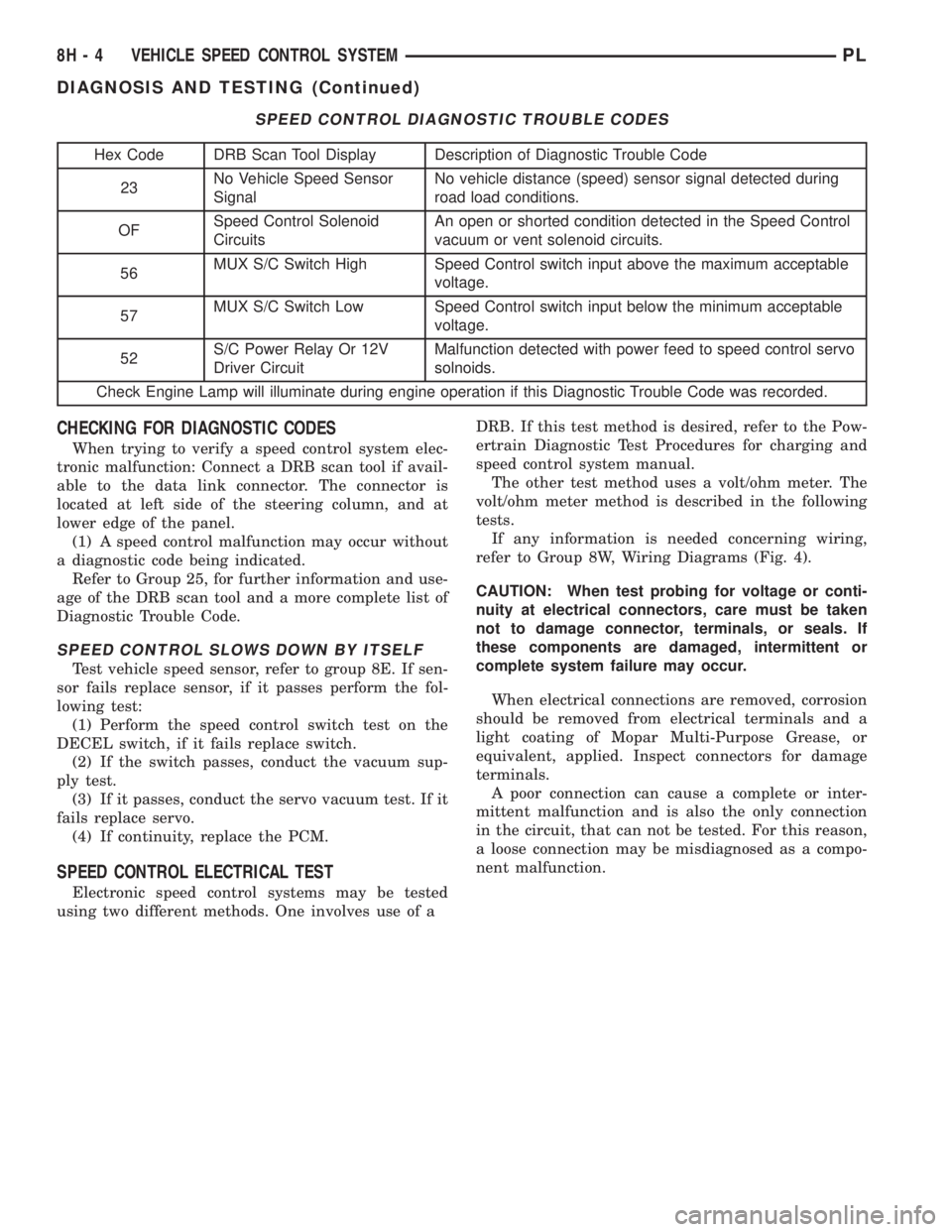
SPEED CONTROL DIAGNOSTIC TROUBLE CODES
Hex Code DRB Scan Tool Display Description of Diagnostic Trouble Code
23No Vehicle Speed Sensor
SignalNo vehicle distance (speed) sensor signal detected during
road load conditions.
OFSpeed Control Solenoid
CircuitsAn open or shorted condition detected in the Speed Control
vacuum or vent solenoid circuits.
56MUX S/C Switch High Speed Control switch input above the maximum acceptable
voltage.
57MUX S/C Switch Low Speed Control switch input below the minimum acceptable
voltage.
52S/C Power Relay Or 12V
Driver CircuitMalfunction detected with power feed to speed control servo
solnoids.
Check Engine Lamp will illuminate during engine operation if this Diagnostic Trouble Code was recorded.
8H - 4 VEHICLE SPEED CONTROL SYSTEMPL
DIAGNOSIS AND TESTING (Continued)
Page 302 of 1200
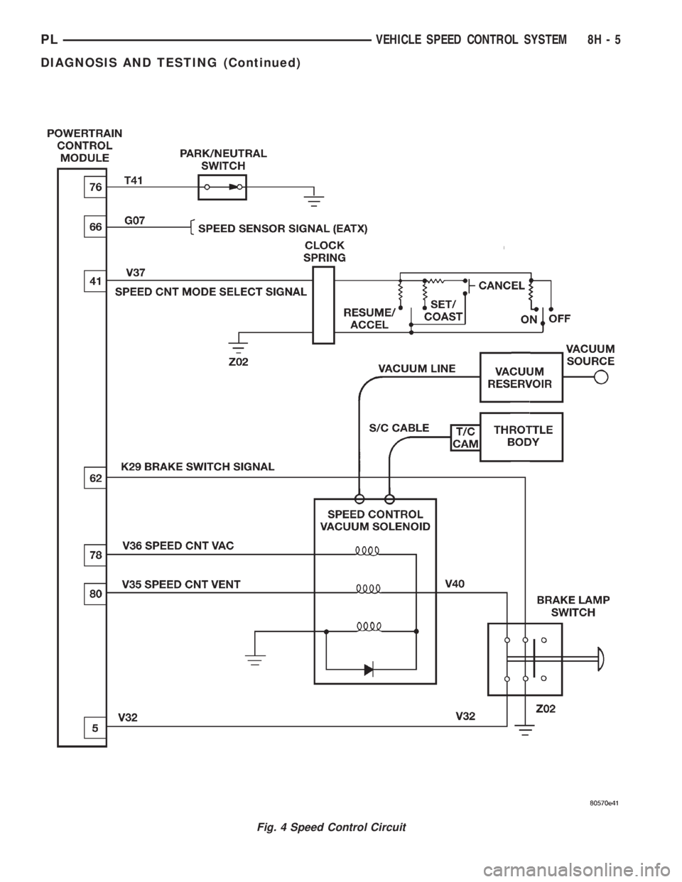
Fig. 4 Speed Control Circuit
PLVEHICLE SPEED CONTROL SYSTEM 8H - 5
DIAGNOSIS AND TESTING (Continued)
Page 303 of 1200
OVERSHOOT/UNDERSHOOT FOLLOWING SPEED
CONTROL SET
If the operator repeatedly presses and releases the
set button with their foot off of the accelerator (a ªlift
foot setº to begin speed control operation), the vehicle
may accelerate and exceed the desired set speed by
up to 5 MPH (8 km/h) and then decelerate to less
than the desired set speed before finally achieving
the desired set speed.
The Speed Control has an adaptive strategy that
compensates for vehicle-to-vehicle variations in speed
control cable lengths. When the speed control is set
with the vehicle operators foot off of the accelerator
pedal, the speed control thinks there is excessive
speed control cable slack and adapts. If the lift foot
sets are continually used, the speed control over-
shoot/undershoot condition will develop.
To ªunlearnº the overshoot/undershoot condition,
the vehicle operator has to press and release the set
button while maintaining the desired set speed with
the accelerator pedal (not decelerating or accelerat-
ing), and then turn the cruise control switch to the
OFF position (or press the CANCEL button if
equipped) after waiting 10 seconds. This procedure
must be performed approximately 10±15 times to
completely unlearn the overshoot/undershoot condi-
tion.
SERVO VACUUM TEST
(1) Turn ignition switch to the ON position with-
out starting engine. Activate speed control ON
switch.
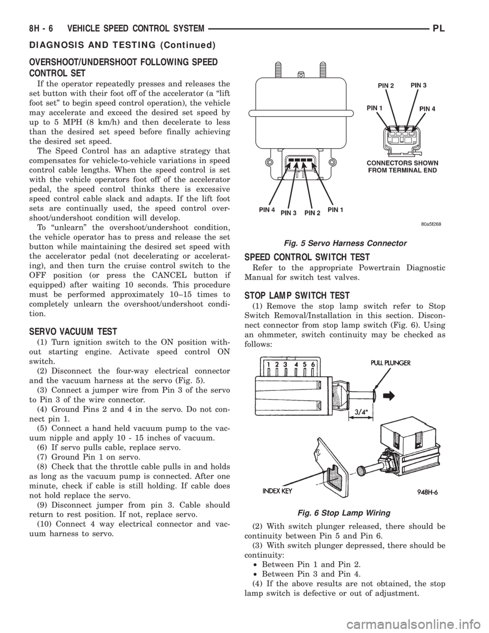
(2) Disconnect the four-way electrical connector
and the vacuum harness at the servo (Fig. 5).
(3) Connect a jumper wire from Pin 3 of the servo
to Pin 3 of the wire connector.
(4) Ground Pins 2 and 4 in the servo. Do not con-
nect pin 1.
(5) Connect a hand held vacuum pump to the vac-
uum nipple and apply 10 - 15 inches of vacuum.
(6) If servo pulls cable, replace servo.
(7) Ground Pin 1 on servo.
(8) Check that the throttle cable pulls in and holds
as long as the vacuum pump is connected. After one
minute, check if cable is still holding. If cable does
not hold replace the servo.
(9) Disconnect jumper from pin 3. Cable should
return to rest position. If not, replace servo.
(10) Connect 4 way electrical connector and vac-
uum harness to servo.
SPEED CONTROL SWITCH TEST
Refer to the appropriate Powertrain Diagnostic
Manual for switch test valves.
STOP LAMP SWITCH TEST
(1) Remove the stop lamp switch refer to Stop
Switch Removal/Installation in this section. Discon-
nect connector from stop lamp switch (Fig. 6). Using
an ohmmeter, switch continuity may be checked as
follows:
(2) With switch plunger released, there should be
continuity between Pin 5 and Pin 6.
(3) With switch plunger depressed, there should be
continuity:
²Between Pin 1 and Pin 2.
²Between Pin 3 and Pin 4.
(4) If the above results are not obtained, the stop
lamp switch is defective or out of adjustment.
Fig. 5 Servo Harness Connector
Fig. 6 Stop Lamp Wiring
8H - 6 VEHICLE SPEED CONTROL SYSTEMPL
DIAGNOSIS AND TESTING (Continued)
Page 304 of 1200
(5) Stop lamp switch adjustment is detailed in
Group 5, Brakes.
ELECTRICAL TESTS AT POWERTRAIN CONTROL
MODULE
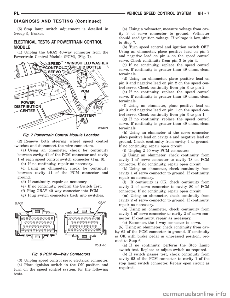
(1) Unplug the GRAY 40-way connector from the
Powertrain Control Module (PCM), (Fig. 7).
(2) Remove both steering wheel speed control
switches and disconnect the wire connectors.
(a) Using an ohmmeter, check for continuity
between cavity 41 of the PCM connector and cavity
1 of each speed control switch connector (Fig. 8).
(b) If no continuity, repair as necessary.
(c) Using an ohmmeter, check for continuity
between cavity 41 of the PCM connector and
ground.
(d) If continuity, repair as necessary.
(e) If no continuity, perform the Switch Test.
(f) Plug GRAY 40 way connector into PCM.
(g) Plug switch connectors back into switches.
(3) Unplug speed control servo electrical connector.
(4) Place ignition switch in the ON position and
turn on the speed control system, for the following
tests.(a) Using a voltmeter, measure voltage from cav-
ity 3 of servo connector to ground. Voltmeter
should read ignition voltage. If voltage is low, skip
to Step 7.
(b) Turn speed control and ignition switch OFF.
Using an ohmmeter, place positive lead on pin 3
and negative lead on pin 4 on the speed control
servo. Check continuity from pin 3 to pin 4.
(c) If no continuity, replace the speed control
servo. If continuity is greater than 49 ohms, clean
terminals.
(d) Using an ohmmeter, place positive lead on
pin 3 and negative lead on pin 2 on the speed con-
trol servo. Check continuity from pin 3 to pin 2.
(e) If no continuity, replace the speed control
servo. If continuity is greater than 49 ohms, clean
terminals.
(f) Using an ohmmeter, place positive lead on
pin 3 and negative lead on pin 1 on the speed con-
trol servo. Check continuity from pin 3 to pin 1.
(g) If no continuity, replace the speed control
servo. If continuity is greater than 49 ohms, clean
terminals.
(h) Using an ohmmeter at the servo connector,
place positive lead on cavity 4 and negative lead on
ground. Check continuity from cavity 4 to ground.
If no continuity, repair open circuit
(i) Unplug 2 40-way PCM connectors
(j) Using an ohmmeter, check continuity from
cavity 1 of servo connector to cavity 78 on PCM
connector. If no continuity, repair open circuit
(k) Using an ohmmeter, check continuity from
cavity 1 of servo connector to ground. If continuity,
repair as necessary.
(l) If continuity is OK, check continuity from
cavity 2 of servo connector to cavity 80 of PCM
connector. If no continuity, repair open circuit
(m) Using an ohmmeter, check continuity from
cavity 2 of servo connector to ground. If continuity,
repair as necessary.
(n) Using an ohmmeter, check continuity from
cavity 1 of servo connector to cavity 2 of servo con-
nector. If continuity, repair as necessary.
(o) Reconnect the 4 way connector to servo.
(5) Using an ohmmeter, check continuity from cav-
ity 62 of the PCM connector to ground. If continuity
is OK with brake pedal in unpressed position, pro-
ceed to Step 6.
(a) If no continuity, perform the Stop Lamp
switch test. Replace or adjust switch as required.
(b) If switch passes test, check continuity from
cavity 62 of the PCM connector to cavity 1 of the
stop lamp switch connector. Repair open circuit as
required.
Fig. 7 Powertrain Control Module Location
Fig. 8 PCM 40ÐWay Connectors
PLVEHICLE SPEED CONTROL SYSTEM 8H - 7
DIAGNOSIS AND TESTING (Continued)
Page 305 of 1200
(c) If continuity is OK between cavity 62 and
cavity 1, repair open circuit between cavity 2 of the
stop lamp switch connector and ground.
(6) Using an ohmmeter, check continuity from cav-
ity 76 on PCM connector to ground with the trans-
mission in park or neutral. If no continuity, test TRS/
Park-Neutral switch and switch wiring
(7) Turn speed control and ignition switch OFF.
(8) Unplug the BLACK 40-way connector from the
Powertrain Control Module (PCM)
(9) Using an ohmmeter, check continuity from cav-
ity 3 of servo connector to cavity 5 on the PCM con-
nector.
(a) If continuity is OK, replace PCM. Check cir-
cuit for short to ground before replacing PCM.
(b) If no continuity, remove stop lamp switch
and conduct Stop Lamp Switch Test. If test fails,
adjust or replace as necessary.
(c) If switch passes, measure continuity from
cavity 4 of stop lamp switch connector to cavity 3
of servo connector. Repair open circuit if necessary.
(d) If continuity is OK, measure continuity from
cavity 3 of stop lamp switch to cavity 5 of PCM
connector. Repair open circuit as necessary.
(e) Install PCM connectors onto PCM and speed
control servo connector to servo.
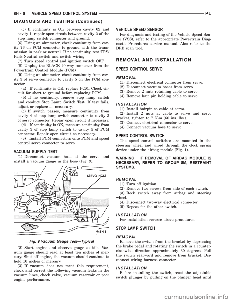
VACUUM SUPPLY TEST
(1) Disconnect vacuum hose at the servo and
install a vacuum gauge in the hose (Fig. 9).
(2) Start engine and observe gauge at idle. Vac-
uum gauge should read at least ten inches of mer-
cury. Shut off engine, the vacuum should continue to
hold 10 inches of mercury.
(3) If vacuum does not meet this requirement,
check and correct the following vacuum leaks in the
vacuum lines, check valve, vacuum reservoir or poor
engine performance.
VEHICLE SPEED SENSOR
For diagnosis and testing of the Vehicle Speed Sen-
sor (VSS), refer to the appropriate Powertrain Diag-
nostic Procedures service manual. Also refer to the
DRB scan tool.
REMOVAL AND INSTALLATION
SPEED CONTROL SERVO
REMOVAL
(1) Disconnect electrical connector from servo.
(2) Disconnect vacuum hoses from servo
(3) Remove 2 nuts retaining cable to servo.
(4) Remove hair pin holding cable to servo.
INSTALLATION
(1) Install hairpin to cable at servo.
(2) Install 2 nuts at cable to servo and servo
bracket, tighten to 7 N´m (60 ins. lbs.).
(3) Connect electrical connector to servo.
(4) Connect vacuum hose to servo
SPEED CONTROL SWITCH
The speed control switches are mounted in the
steering wheel and wired through the clock spring
device under the airbag module (Fig. 1).
WARNING: IF REMOVAL OF AIRBAG MODULE IS
NECESSARY, REFER TO GROUP 8M, RESTRAINT
SYSTEMS.
REMOVAL
(1) Turn off ignition.
(2) Remove two screws from side of each switch.
(3) Rock switch away from airbag and steering
wheel.
(4) Disconnect two-way electrical connector.
(5) Repeat for the other switch.
INSTALLATION
For installation reverse above procedures.
STOP LAMP SWITCH
REMOVAL
Remove the switch from the bracket by depressing
the brake pedal and rotating the switch in a counter-
clockwise direction approximately 30 degrees. Pull
the switch rearward and remove from bracket. Dis-
connect wiring harness connector.
INSTALLATION
Before installing the switch, reset the adjustable
switch plunger by pulling on the plunger head until
Fig. 9 Vacuum Gauge TestÐTypical
8H - 8 VEHICLE SPEED CONTROL SYSTEMPL
DIAGNOSIS AND TESTING (Continued)
Page 306 of 1200
the plunger reaches the end of its travel. A ratchet-
ing sound will be heard during this procedure.
Connect the wiring harness to the switch. Mount
the switch into the bracket by holding the switch
with the plunger facing forward in car. There is an
index key on the switch that mates with the bracket
slot at the top of the square hole. Align key and push
switch into square hole in bracket while depressing
the brake pedal. Once the switch is seated in the
hole, rotate clockwise approximately 30 degrees to
lock into place. The switch will automatically adjust
when the pedal is released. Pull back on the pedal to
assure correct adjustment.
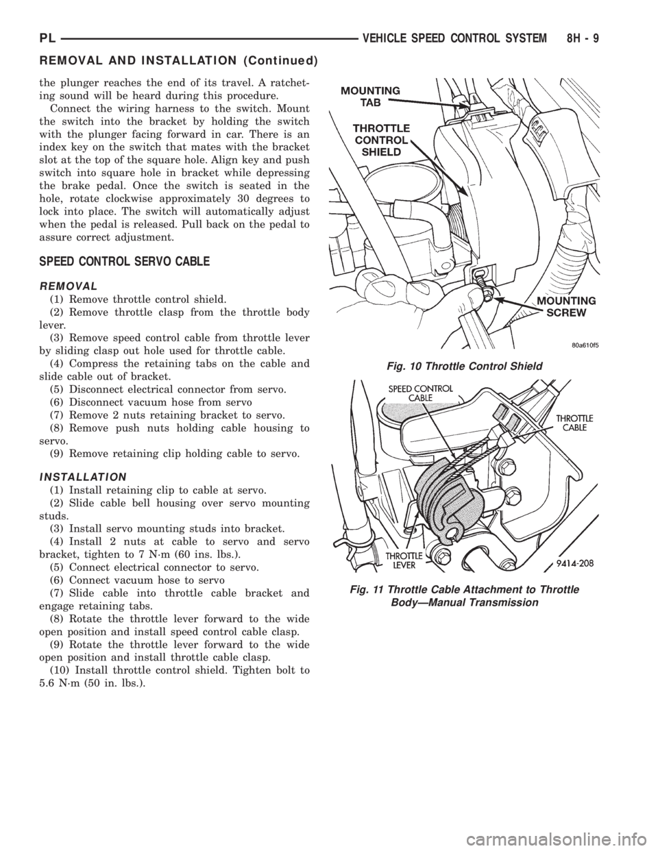
SPEED CONTROL SERVO CABLE
REMOVAL
(1) Remove throttle control shield.
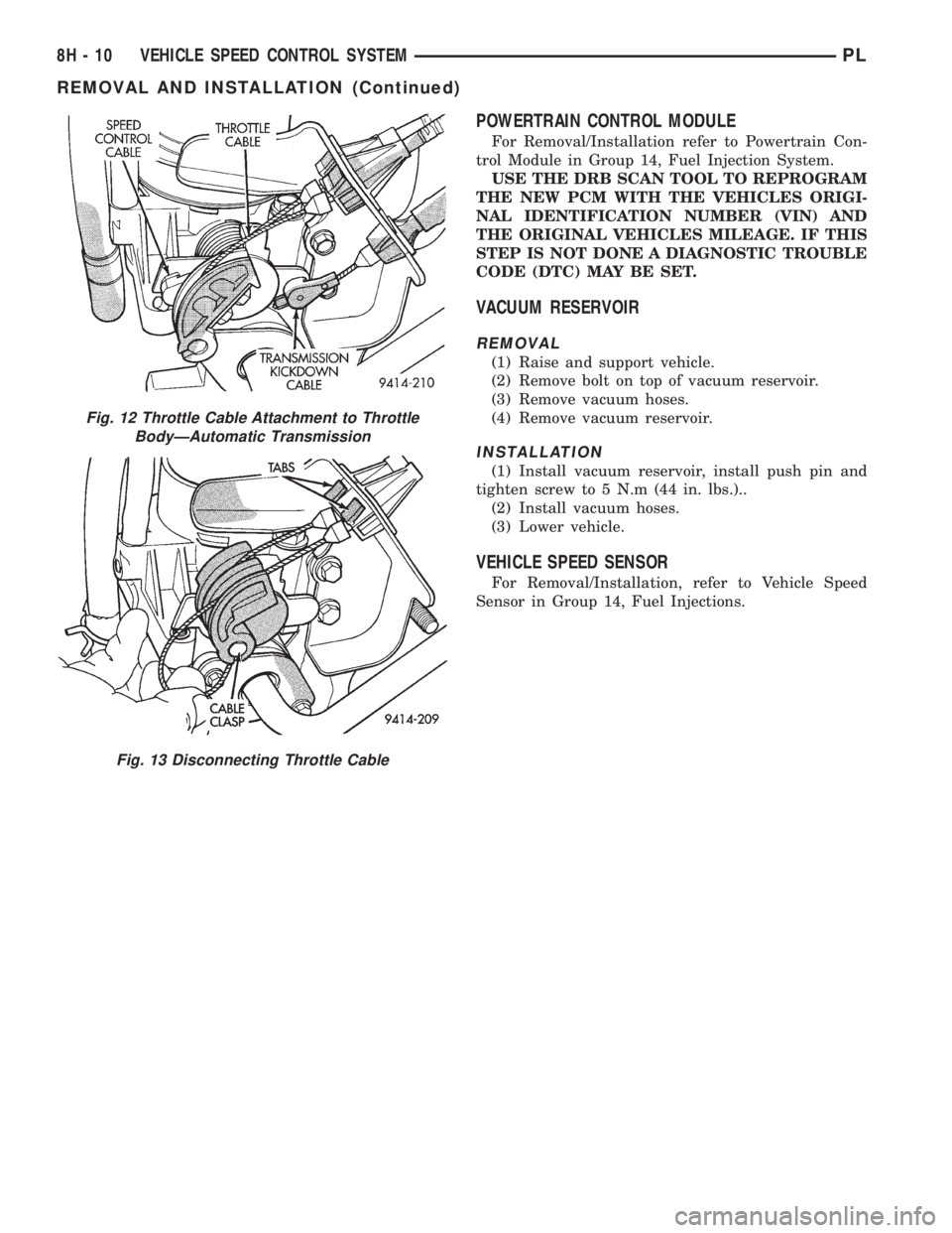
(2) Remove throttle clasp from the throttle body
lever.
(3) Remove speed control cable from throttle lever
by sliding clasp out hole used for throttle cable.
(4) Compress the retaining tabs on the cable and
slide cable out of bracket.
(5) Disconnect electrical connector from servo.
(6) Disconnect vacuum hose from servo
(7) Remove 2 nuts retaining bracket to servo.
(8) Remove push nuts holding cable housing to
servo.
(9) Remove retaining clip holding cable to servo.
INSTALLATION
(1) Install retaining clip to cable at servo.
(2) Slide cable bell housing over servo mounting
studs.
(3) Install servo mounting studs into bracket.
(4) Install 2 nuts at cable to servo and servo
bracket, tighten to 7 N´m (60 ins. lbs.).
(5) Connect electrical connector to servo.
(6) Connect vacuum hose to servo
(7) Slide cable into throttle cable bracket and
engage retaining tabs.
(8) Rotate the throttle lever forward to the wide
open position and install speed control cable clasp.
(9) Rotate the throttle lever forward to the wide
open position and install throttle cable clasp.
(10) Install throttle control shield. Tighten bolt to
5.6 N´m (50 in. lbs.).
Fig. 10 Throttle Control Shield
Fig. 11 Throttle Cable Attachment to Throttle
BodyÐManual Transmission
PLVEHICLE SPEED CONTROL SYSTEM 8H - 9
REMOVAL AND INSTALLATION (Continued)
Page 307 of 1200
POWERTRAIN CONTROL MODULE
For Removal/Installation refer to Powertrain Con-
trol Module in Group 14, Fuel Injection System.
USE THE DRB SCAN TOOL TO REPROGRAM
THE NEW PCM WITH THE VEHICLES ORIGI-
NAL IDENTIFICATION NUMBER (VIN) AND
THE ORIGINAL VEHICLES MILEAGE. IF THIS
STEP IS NOT DONE A DIAGNOSTIC TROUBLE
CODE (DTC) MAY BE SET.
VACUUM RESERVOIR
REMOVAL
(1) Raise and support vehicle.
(2) Remove bolt on top of vacuum reservoir.
(3) Remove vacuum hoses.
(4) Remove vacuum reservoir.
INSTALLATION
(1) Install vacuum reservoir, install push pin and
tighten screw to 5 N.m (44 in. lbs.)..
(2) Install vacuum hoses.
(3) Lower vehicle.
VEHICLE SPEED SENSOR
For Removal/Installation, refer to Vehicle Speed
Sensor in Group 14, Fuel Injections.
Fig. 12 Throttle Cable Attachment to Throttle
BodyÐAutomatic Transmission
Fig. 13 Disconnecting Throttle Cable
8H - 10 VEHICLE SPEED CONTROL SYSTEMPL
REMOVAL AND INSTALLATION (Continued)
Page 308 of 1200
VEHICLE SPEED CONTROL SYSTEM
CONTENTS
page
REMOVAL AND INSTALLATION
SPEED CONTROL SERVO................ 1
REMOVAL AND INSTALLATION
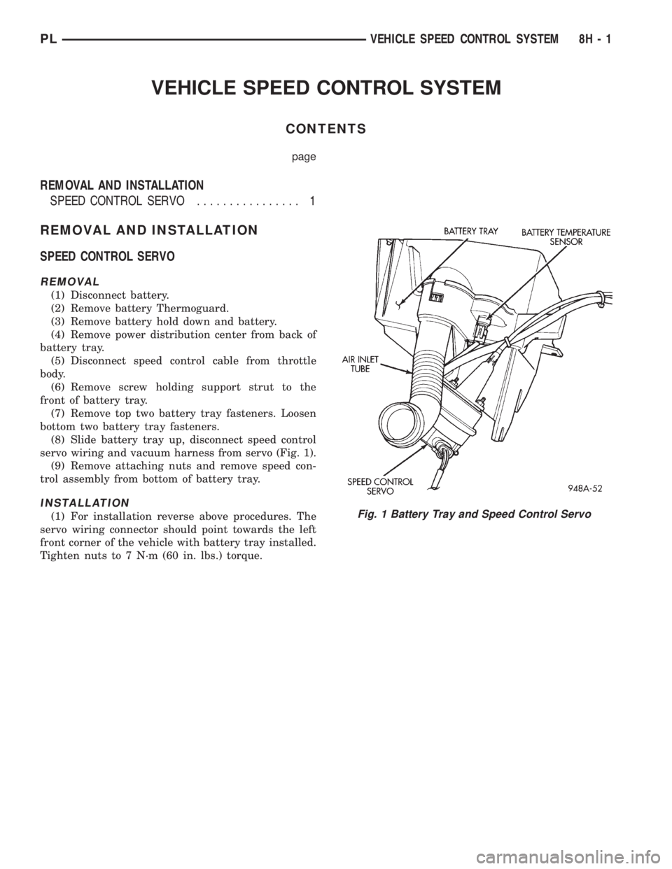
SPEED CONTROL SERVO
REMOVAL
(1) Disconnect battery.
(2) Remove battery Thermoguard.
(3) Remove battery hold down and battery.
(4) Remove power distribution center from back of
battery tray.
(5) Disconnect speed control cable from throttle
body.
(6) Remove screw holding support strut to the
front of battery tray.
(7) Remove top two battery tray fasteners. Loosen
bottom two battery tray fasteners.
(8) Slide battery tray up, disconnect speed control
servo wiring and vacuum harness from servo (Fig. 1).
(9) Remove attaching nuts and remove speed con-
trol assembly from bottom of battery tray.
INSTALLATION
(1) For installation reverse above procedures. The
servo wiring connector should point towards the left
front corner of the vehicle with battery tray installed.
Tighten nuts to 7 N´m (60 in. lbs.) torque.Fig. 1 Battery Tray and Speed Control Servo
PLVEHICLE SPEED CONTROL SYSTEM 8H - 1
Page 309 of 1200

Page 310 of 1200
TURN SIGNAL AND FLASHERS
CONTENTS
page page
GENERAL INFORMATION
INTRODUCTION......................... 1
DESCRIPTION AND OPERATION
COMBINATION FLASHER.................. 1
HAZARD WARNING SYSTEM............... 1DIAGNOSIS AND TESTING
MULTI-FUNCTION SWITCH................ 2
MULTI-FUNCTION SWITCH TEST............ 2
REMOVAL AND INSTALLATION
MULTI-FUNCTION SWITCH................ 4
GENERAL INFORMATION
INTRODUCTION
WARNING: ON VEHICLES EQUIPPED WITH AIR-
BAG, SEE GROUP 8M, RESTRAINT SYSTEMS FOR
AIRBAG REMOVAL PROCEDURES.
The turn signals are part of the multi-function
switch. Which contains:
²Electrical circuitry for turn signals
²Hazard warning switch
²Headlamp beam select switch
²Headlamp optical horn
The integrated switch assembly is mounted to the
left hand side of the steering column. When the
driver wishes to signal his intentions to change direc-
tion of travel, he moves the lever upward to cause
the right signals to flash and downward to cause the
left signals to flash. After completion of a turn the
system is deactivated automatically. As the steering
wheel returns to the straight ahead position, a can-
celing cam molded to the clockspring mechanism
comes in contact with the cancel actuator on the turn
signal multi-function switch assembly. The cam lobe,
pushing on the cancel actuator, returns the switch to
the off position.
If only momentary signaling such as indication of a
lane change is desired, the switch is actuated to a
left or right intermediate detent position. In this
position the signal lamps flash as described above,
but the switch returns to the OFF position as soon as
the lever is released.
When the system is activated, one of two indicator
lamps mounted in the instrument cluster flashes in
unison with the turn signal lamps, indicating to the
driver that the system is operating.
DESCRIPTION AND OPERATION
HAZARD WARNING SYSTEM
The hazard warning system is actuated by a slide
button located on the top of the steering column
between the steering wheel and the instrument
panel. The hazard switch is identified with a double
triangle on front of the button.
COMBINATION FLASHER
The turn signal flasher and the hazard warning
flasher are combined into one unit called a combina-
tion flasher (combo-flasher). The combo- flasher con-
trols the flashing of the hazard warning system and
the turn signal system. An inoperative bulb or incom-
plete turn signal circuit will cause the flasher rate to
double.
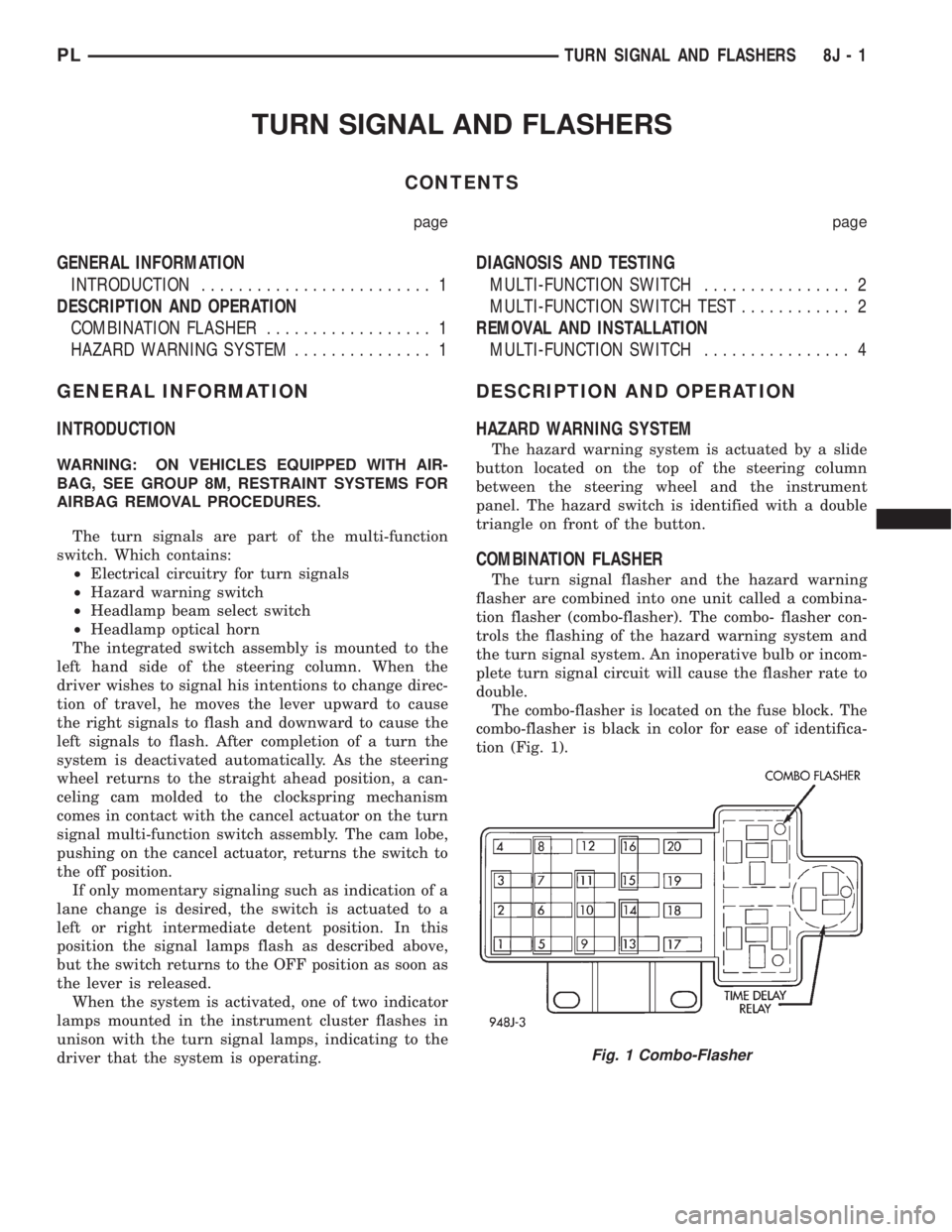
The combo-flasher is located on the fuse block. The
combo-flasher is black in color for ease of identifica-
tion (Fig. 1).
Fig. 1 Combo-Flasher
PLTURN SIGNAL AND FLASHERS 8J - 1