DODGE NEON 1999 Service Repair Manual
Manufacturer: DODGE, Model Year: 1999, Model line: NEON, Model: DODGE NEON 1999Pages: 1200, PDF Size: 35.29 MB
Page 281 of 1200
(6) Remove the screws attaching lens, dial and
gauge assembly to the housing. The bottom screws
attaching lens to the housing can be accessed without
removing the foam pad.
(7) Remove the lens, dial and gauge assembly from
housing.
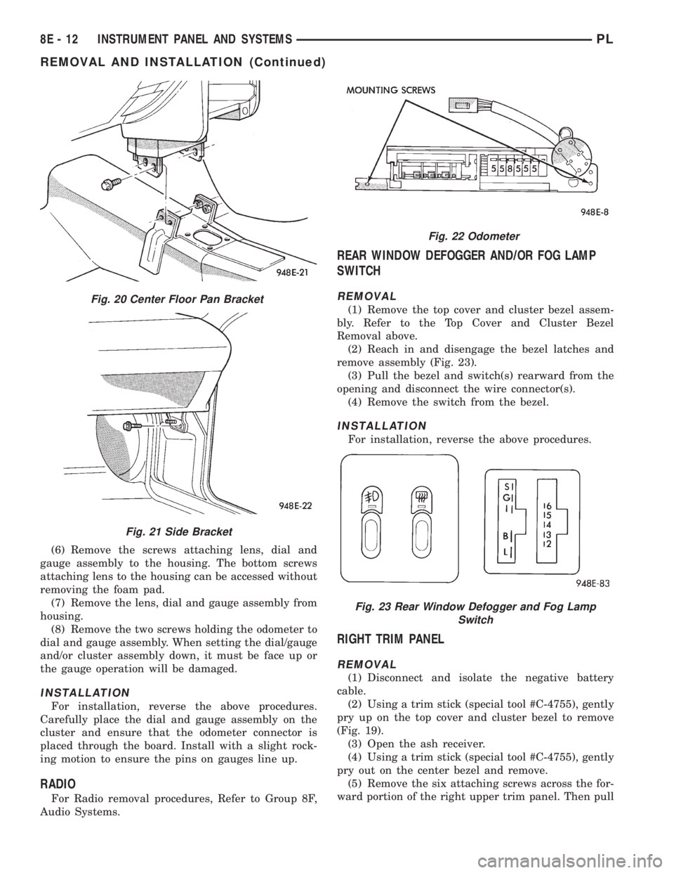
(8) Remove the two screws holding the odometer to
dial and gauge assembly. When setting the dial/gauge
and/or cluster assembly down, it must be face up or
the gauge operation will be damaged.
INSTALLATION
For installation, reverse the above procedures.
Carefully place the dial and gauge assembly on the
cluster and ensure that the odometer connector is
placed through the board. Install with a slight rock-
ing motion to ensure the pins on gauges line up.
RADIO
For Radio removal procedures, Refer to Group 8F,
Audio Systems.
REAR WINDOW DEFOGGER AND/OR FOG LAMP
SWITCH
REMOVAL
(1) Remove the top cover and cluster bezel assem-
bly. Refer to the Top Cover and Cluster Bezel
Removal above.
(2) Reach in and disengage the bezel latches and
remove assembly (Fig. 23).
(3) Pull the bezel and switch(s) rearward from the
opening and disconnect the wire connector(s).
(4) Remove the switch from the bezel.
INSTALLATION
For installation, reverse the above procedures.
RIGHT TRIM PANEL
REMOVAL
(1) Disconnect and isolate the negative battery
cable.
(2) Using a trim stick (special tool #C-4755), gently
pry up on the top cover and cluster bezel to remove
(Fig. 19).
(3) Open the ash receiver.
(4) Using a trim stick (special tool #C-4755), gently
pry out on the center bezel and remove.
(5) Remove the six attaching screws across the for-
ward portion of the right upper trim panel. Then pull
Fig. 20 Center Floor Pan Bracket
Fig. 21 Side Bracket
Fig. 22 Odometer
Fig. 23 Rear Window Defogger and Fog Lamp
Switch
8E - 12 INSTRUMENT PANEL AND SYSTEMSPL
REMOVAL AND INSTALLATION (Continued)
Page 282 of 1200
the panel rearward to disengage the three locator
pins and remove.
(6) Reach in and disconnect the wiring connector(s)
for the rear window defogger and/or fog lamp
switch(s) as required.
INSTALLATION
For installation, reverse the above procedures.
SHIFTER KNOB
AUTOMATIC TRANSMISSION SHIFTER
REMOVAL
(1) Loosen the set screw at the left side under the
button area.
(2) Pull up until the knob slides off the shifter
shaft.
INSTALLATION
For installation, reverse the above procedures.
MANUAL TRANSMISSION SHIFTER
REMOVAL
(1) Pull the top part of the boot down until the two
tabs at the bottom of the knob are exposed.
(2) Release the locking tabs from the pins on the
shifter shaft.
(3) Pull up until the knob slides off the shifter
shaft.INSTALLATION
For installation, reverse the above procedures.
STEERING COLUMN COVER
REMOVAL
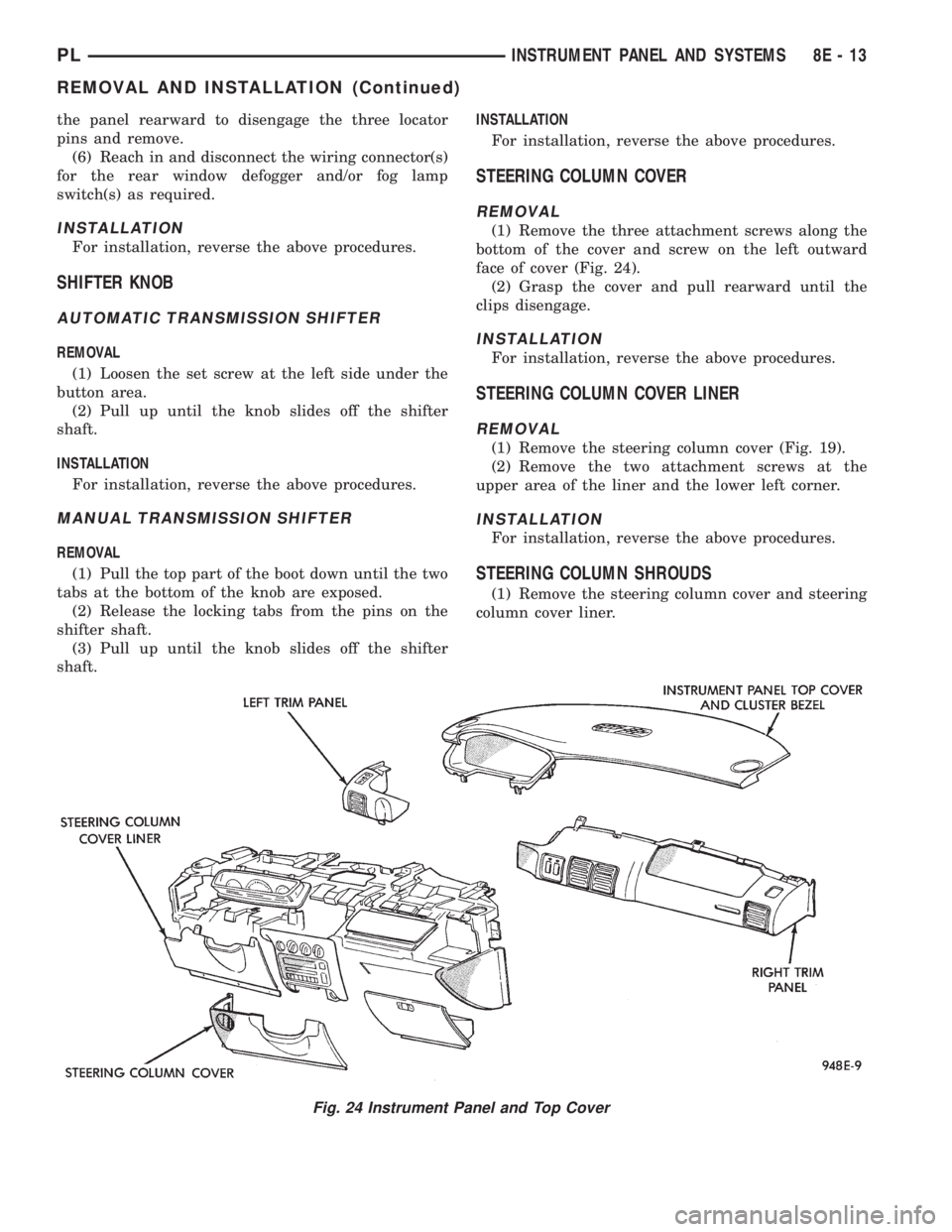
(1) Remove the three attachment screws along the
bottom of the cover and screw on the left outward
face of cover (Fig. 24).
(2) Grasp the cover and pull rearward until the
clips disengage.
INSTALLATION
For installation, reverse the above procedures.
STEERING COLUMN COVER LINER
REMOVAL
(1) Remove the steering column cover (Fig. 19).
(2) Remove the two attachment screws at the
upper area of the liner and the lower left corner.
INSTALLATION
For installation, reverse the above procedures.
STEERING COLUMN SHROUDS
(1) Remove the steering column cover and steering
column cover liner.
Fig. 24 Instrument Panel and Top Cover
PLINSTRUMENT PANEL AND SYSTEMS 8E - 13
REMOVAL AND INSTALLATION (Continued)
Page 283 of 1200
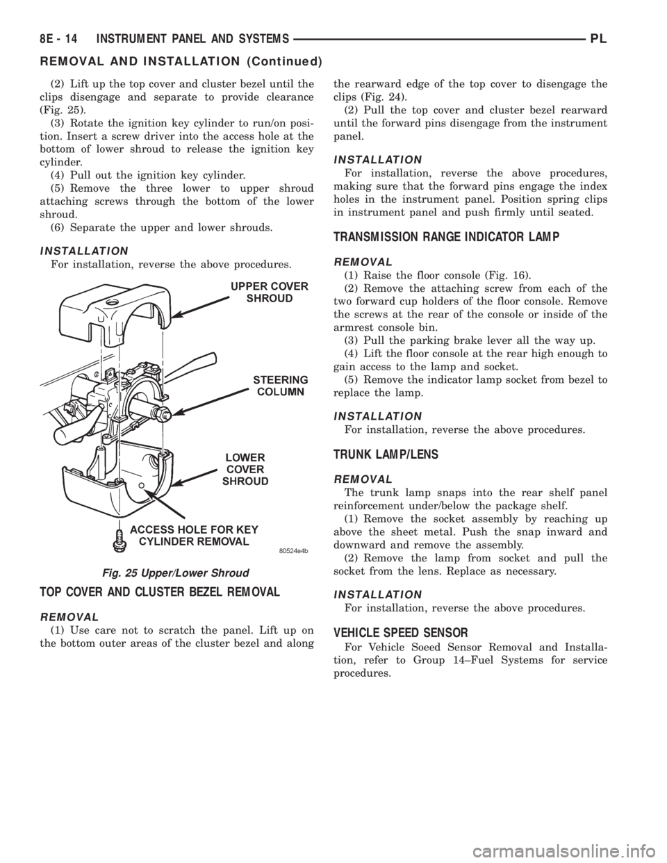
(2) Lift up the top cover and cluster bezel until the
clips disengage and separate to provide clearance
(Fig. 25).
(3) Rotate the ignition key cylinder to run/on posi-
tion. Insert a screw driver into the access hole at the
bottom of lower shroud to release the ignition key
cylinder.
(4) Pull out the ignition key cylinder.
(5) Remove the three lower to upper shroud
attaching screws through the bottom of the lower
shroud.
(6) Separate the upper and lower shrouds.
INSTALLATION
For installation, reverse the above procedures.
TOP COVER AND CLUSTER BEZEL REMOVAL
REMOVAL
(1) Use care not to scratch the panel. Lift up on
the bottom outer areas of the cluster bezel and alongthe rearward edge of the top cover to disengage the
clips (Fig. 24).
(2) Pull the top cover and cluster bezel rearward
until the forward pins disengage from the instrument
panel.
INSTALLATION
For installation, reverse the above procedures,
making sure that the forward pins engage the index
holes in the instrument panel. Position spring clips
in instrument panel and push firmly until seated.
TRANSMISSION RANGE INDICATOR LAMP
REMOVAL
(1) Raise the floor console (Fig. 16).
(2) Remove the attaching screw from each of the
two forward cup holders of the floor console. Remove
the screws at the rear of the console or inside of the
armrest console bin.
(3) Pull the parking brake lever all the way up.
(4) Lift the floor console at the rear high enough to
gain access to the lamp and socket.
(5) Remove the indicator lamp socket from bezel to
replace the lamp.
INSTALLATION
For installation, reverse the above procedures.
TRUNK LAMP/LENS
REMOVAL
The trunk lamp snaps into the rear shelf panel
reinforcement under/below the package shelf.
(1) Remove the socket assembly by reaching up
above the sheet metal. Push the snap inward and
downward and remove the assembly.
(2) Remove the lamp from socket and pull the
socket from the lens. Replace as necessary.
INSTALLATION
For installation, reverse the above procedures.
VEHICLE SPEED SENSOR
For Vehicle Soeed Sensor Removal and Installa-
tion, refer to Group 14±Fuel Systems for service
procedures.
Fig. 25 Upper/Lower Shroud
8E - 14 INSTRUMENT PANEL AND SYSTEMSPL
REMOVAL AND INSTALLATION (Continued)
Page 284 of 1200
INSTRUMENT PANEL AND SYSTEMS
CONTENTS
page page
DIAGNOSIS AND TESTING
FOG LAMP SWITCH TEST................ 1
HEADLAMP LEVELING SWITCH........... 1
INSTRUMENT PANEL AND COMPONENTS . . . 2
REMOVAL AND INSTALLATION
END CAP RHD ......................... 2FRONT FOG LAMP SWITCH.............. 2
HEADLAMP LEVELING SWITCH........... 3
REAR WINDOW DEFOGGER AND/OR REAR
FOG LAMP SWITCH................... 3
DIAGNOSIS AND TESTING
FOG LAMP SWITCH TEST
Refer to Group 8W, Wiring Diagrams for wiring or
circuit information.
FRONT
(1) Remove the fog lamp switch and disconnect the
connector at the center stack.
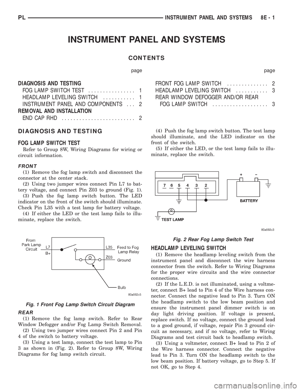
(2) Using two jumper wires connect Pin L7 to bat-
tery voltage, and connect Pin Z03 to ground (Fig. 1).
(3) Push the fog lamp switch button. The LED
indicator on the front of the switch should illuminate.
Check Pin L35 with a test lamp for battery voltage.
(4) If either the LED or the test lamp fails to illu-
minate, replace the switch.
REAR
(1) Remove the fog lamp switch. Refer to Rear
Window Defogger and/or Fog Lamp Switch Removal.
(2) Using two jumper wires connect Pin 2 and Pin
4 of the switch to battery voltage.
(3) Using a test lamp, connect the test lamp to Pin
3 as shown in (Fig. 2). Refer to Group 8W, Wiring
Diagrams for fog lamp switch circuit.(4) Push the fog lamp switch button. The test lamp
should illuminate, and the LED indicator on the
front of the switch.
(5) If either the LED, or the test lamp fails to illu-
minate, replace the switch.
HEADLAMP LEVELING SWITCH
(1) Remove the headlamp leveling switch from the
instrument panel and disconnect the wire harness
connector from the switch. Refer to Wiring Diagrams
for the proper wire circuits and the wire connector
connections.
(2) If the L.E.D. is not illuminated, using a voltme-
ter, connect B+ lead to Pin 4 of the Wire harness con-
nector. Connect the negative lead to Pin 3. Turn ON
the headlamp switch to the low beam position and
ensure the instrument panel dimmer switch is on
day light driving position. If voltage is present,
replace switch. If no voltage, connect the ground lead
to a good ground, if voltage, repair Pin 3 ground cir-
cuit as necessary, and if no voltage, refer to Wiring
Diagrams and test circuit back to headlamp switch.
(3) Using a voltmeter, connect B+ lead to Pin 2 of
the Wire harness connector. Connect the negative
lead to Pin 3. Turn ON the headlamp switch to the
low beam position. If battery voltage, go to Step 5. If
not OK, go to Step 4.
Fig. 1 Front Fog Lamp Switch Circuit Diagram
Fig. 2 Rear Fog Lamp Switch Test
PLINSTRUMENT PANEL AND SYSTEMS 8E - 1
Page 285 of 1200
(4) Connect the ground lead to a good ground, if no
voltage, refer to Wiring Diagrams and test circuit
back to headlamp switch. If battery voltage, repair
Pin 3 ground circuit as necessary.
(5) Turn headlamps OFF. Connect the wire har-
ness connector to the headlamp leveling switch. Turn
ON the headlamp switch to the low beam position.
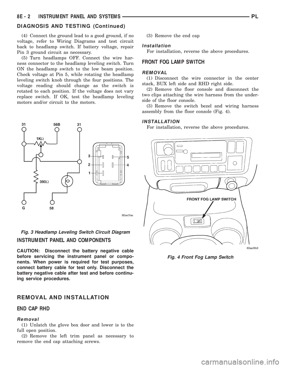
Check voltage at Pin 5, while rotating the headlamp
leveling switch knob through the four positions. The
voltage reading should change as the switch is
rotated to each position. If the voltage does not vary
replace switch. If OK, test the headlamp leveling
motors and/or circuit to the motors.
INSTRUMENT PANEL AND COMPONENTS
CAUTION: Disconnect the battery negative cable
before servicing the instrument panel or compo-
nents. When power is required for test purposes,
connect battery cable for test only. Disconnect the
battery negative cable after test and before continu-
ing service procedures.
REMOVAL AND INSTALLATION
END CAP RHD
Removal
(1) Unlatch the glove box door and lower is to the
full open position.
(2) Remove the left trim panel as necessary to
remove the end cap attaching screws.(3) Remove the end cap
Installation
For installation, reverse the above procedures.
FRONT FOG LAMP SWITCH
REMOVAL
(1) Disconnect the wire connector in the center
stack, BUX left side and RHD right side.
(2) Remove the floor console and disconnect the
two clips attaching the wire harness from the under-
side of the floor console.
(3) Remove the switch bezel and wiring harness
assembly from the floor console (Fig. 4).
INSTALLATION
For installation, reverse the above procedures.
Fig. 3 Headlamp Leveling Switch Circuit Diagram
Fig. 4 Front Fog Lamp Switch
8E - 2 INSTRUMENT PANEL AND SYSTEMSPL
DIAGNOSIS AND TESTING (Continued)
Page 286 of 1200
HEADLAMP LEVELING SWITCH
REMOVAL
(1) Remove the top cover and cluster bezel assem-
bly.
(2) Disengage the headlamp leveling switch bezel
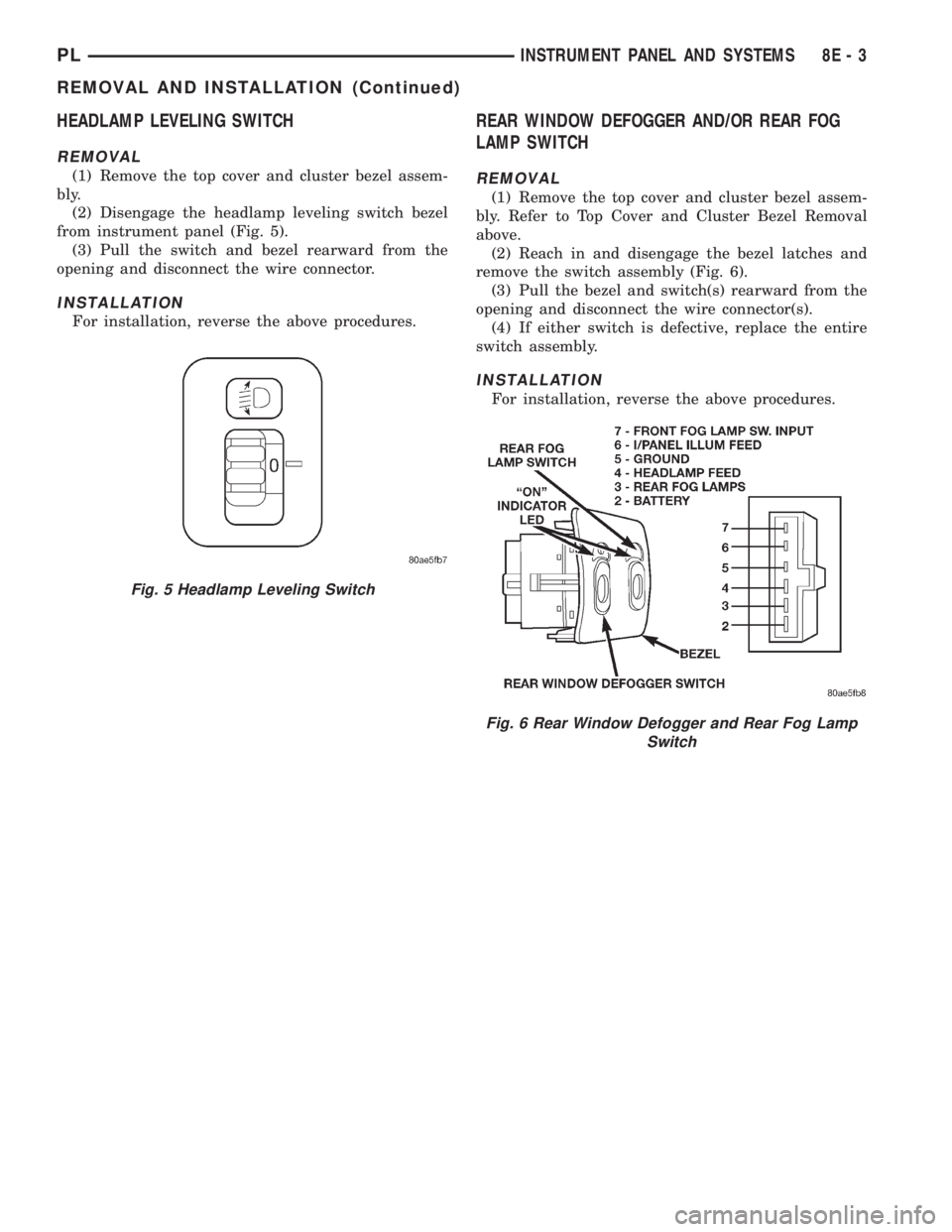
from instrument panel (Fig. 5).
(3) Pull the switch and bezel rearward from the
opening and disconnect the wire connector.
INSTALLATION
For installation, reverse the above procedures.
REAR WINDOW DEFOGGER AND/OR REAR FOG
LAMP SWITCH
REMOVAL
(1) Remove the top cover and cluster bezel assem-
bly. Refer to Top Cover and Cluster Bezel Removal
above.
(2) Reach in and disengage the bezel latches and
remove the switch assembly (Fig. 6).
(3) Pull the bezel and switch(s) rearward from the
opening and disconnect the wire connector(s).
(4) If either switch is defective, replace the entire
switch assembly.
INSTALLATION
For installation, reverse the above procedures.
Fig. 5 Headlamp Leveling Switch
Fig. 6 Rear Window Defogger and Rear Fog Lamp
Switch
PLINSTRUMENT PANEL AND SYSTEMS 8E - 3
REMOVAL AND INSTALLATION (Continued)
Page 287 of 1200

Page 288 of 1200
AUDIO SYSTEM
CONTENTS
page page
GENERAL INFORMATION
INTRODUCTION......................... 1
DESCRIPTION AND OPERATION
INTERFERENCE ELIMINATION.............. 1
DIAGNOSIS AND TESTING
ANTENNA.............................. 3
AUDIO DIAGNOSTIC TEST PROCEDURES..... 1BENCH TEST FOR ANTENNA MALFUNCTION . . 3
REMOVAL AND INSTALLATION
ANTENNA.............................. 3
FRONT DOOR SPEAKER................... 4
INSTRUMENT PANEL SPEAKER............. 4
RADIO................................. 4
REAR SHELF SPEAKER(S)................. 5
GENERAL INFORMATION
INTRODUCTION
Operating instructions for the factory installed
audio systems can be found in the Owner's Manual
provided with the vehicle.
The vehicles are equipped with an Interior (Igni-
tion Off Draw) fuse in the Power Distribution Center
located in the engine compartment. After the Interior
(IOD) fuse or battery has been disconnected the clock
will require resetting.
DESCRIPTION AND OPERATION
INTERFERENCE ELIMINATION
The radio utilizes a ground wire plugged on to a
blade terminal and is bolted to the radio chassis.
Both connector and terminal should be securely
attached. The engine has three separate ground
straps to suppress ignition noise which may interfere
with radio reception.
²Left engine mount clip on strap
²Engine to shock tower reinforcement
²Rear strut to body, clip-on strap
Inductive type spark plug cables in the high ten-
sion circuit of the ignition system complete the inter-
ference suppression. Faulty or deteriorated spark
plug wires should be replaced.
In addition, there is a capacitor mounted on the
cylinder head which also helps suppress ignition
noise.
DIAGNOSIS AND TESTING
AUDIO DIAGNOSTIC TEST PROCEDURES
CAUTION: The CD player will only operate between
approximate temperatures of -23ÉC and +65ÉC (-10ÉF
and +145ÉF).
Whenever a radio malfunction occurs;
(1) First check FUSES:
(a) Power Distribution Center (PDC), Interior
lamp fuse, M1 - Radio Memory Feed
(b) Fuse Block:
(I) Fuse 12, Illumination in the fuse block
(II) Fuse 16, Ignition feed in the fuse block
NOTE: The vehicles are shipped with the INTERIOR
LAMP fuse disconnected.
(2) Verify, the radio wire harness are properly con-
nected before starting normal diagnosis and repair
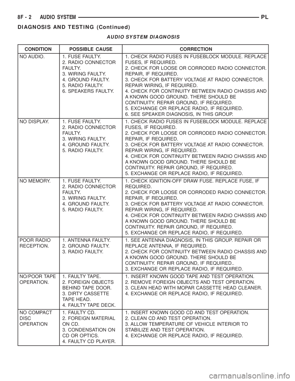
procedures. Refer to Audio Diagnosis table and/or
Group 8W, Wiring Diagrams, Radio Section.
PLAUDIO SYSTEM 8F - 1
Page 289 of 1200
AUDIO SYSTEM DIAGNOSIS
CONDITION POSSIBLE CAUSE CORRECTION
NO AUDIO. 1. FUSE FAULTY.
2. RADIO CONNECTOR
FAULTY.
3. WIRING FAULTY.
4. GROUND FAULTY.
5. RADIO FAULTY.
6. SPEAKERS FAULTY.1. CHECK RADIO FUSES IN FUSEBLOCK MODULE. REPLACE
FUSES, IF REQUIRED.
2. CHECK FOR LOOSE OR CORRODED RADIO CONNECTOR.
REPAIR, IF REQUIRED.
3. CHECK FOR BATTERY VOLTAGE AT RADIO CONNECTOR.
REPAIR WIRING, IF REQUIRED.
4. CHECK FOR CONTINUITY BETWEEN RADIO CHASSIS AND
A KNOWN GOOD GROUND. THERE SHOULD BE
CONTINUITY. REPAIR GROUND, IF REQUIRED.
5. EXCHANGE OR REPLACE RADIO, IF REQUIRED.
6. SEE SPEAKER DIAGNOSIS, IN THIS GROUP.
NO DISPLAY. 1. FUSE FAULTY.
2. RADIO CONNECTOR
FAULTY.
3. WIRING FAULTY.
4. GROUND FAULTY.
5. RADIO FAULTY.1. CHECK RADIO FUSES IN FUSEBLOCK MODULE. REPLACE
FUSES, IF REQUIRED.
2. CHECK FOR LOOSE OR CORRODED RADIO CONNECTOR.
REPAIR, IF REQUIRED.
3. CHECK FOR BATTERY VOLTAGE AT RADIO CONNECTOR.
REPAIR WIRING, IF REQUIRED.
4. CHECK FOR CONTINUITY BETWEEN RADIO CHASSIS AND
A KNOWN GOOD GROUND. THERE SHOULD BE
CONTINUITY. REPAIR GROUND, IF REQUIRED.
5. EXCHANGE OR REPLACE RADIO, IF REQUIRED.
NO MEMORY. 1. FUSE FAULTY.
2. RADIO CONNECTOR
FAULTY.
3. WIRING FAULTY.
4. GROUND FAULTY.
5. RADIO FAULTY.1. CHECK IGNITION-OFF DRAW FUSE. REPLACE FUSE, IF
REQUIRED.
2. CHECK FOR LOOSE OR CORRODED RADIO CONNECTOR.
REPAIR, IF REQUIRED.
3. CHECK FOR BATTERY VOLTAGE AT RADIO CONNECTOR.
REPAIR WIRING, IF REQUIRED.
4. CHECK FOR CONTINUITY BETWEEN RADIO CHASSIS AND
A KNOWN GOOD GROUND. THERE SHOULD BE
CONTINUITY. REPAIR GROUND, IF REQUIRED.
5. EXCHANGE OR REPLACE RADIO, IF REQUIRED.
POOR RADIO
RECEPTION.1. ANTENNA FAULTY.
2. GROUND FAULTY.
3. RADIO FAULTY.1. SEE ANTENNA DIAGNOSIS, IN THIS GROUP. REPAIR OR
REPLACE ANTENNA, IF REQUIRED.
2. CHECK FOR CONTINUITY BETWEEN RADIO CHASSIS AND
A KNOWN GOOD GROUND. THERE SHOULD BE
CONTINUITY. REPAIR GROUND, IF REQUIRED..
3. EXCHANGE OR REPLACE RADIO, IF REQUIRED.
NO/POOR TAPE
OPERATION.1. FAULTY TAPE.
2. FOREIGN OBJECTS
BEHIND TAPE DOOR.
3. DIRTY CASSETTE
TAPE HEAD.
4. FAULTY TAPE DECK.1. INSERT KNOWN GOOD TAPE AND TEST OPERATION.
2. REMOVE FOREIGN OBJECTS AND TEST OPERATION.
3. CLEAN HEAD WITH MOPAR CASSETTE HEAD CLEANER.
4. EXCHANGE OR REPLACE RADIO, IF REQUIRED.
NO COMPACT
DISC
OPERATION1. FAULTY CD.
2. FOREIGN MATERIAL
ON CD.
3. CONDENSATION ON
CD OR OPTICS.
4. FAULTY CD PLAYER.1. INSERT KNOWN GOOD CD AND TEST OPERATION.
2. CLEAN CD AND TEST OPERATION.
3. ALLOW TEMPERATURE OF VEHICLE INTERIOR TO
STABILIZE AND TEST OPERATION.
4. EXCHANGE OR REPLACE RADIO, IF REQUIRED.
8F - 2 AUDIO SYSTEMPL
DIAGNOSIS AND TESTING (Continued)
Page 290 of 1200
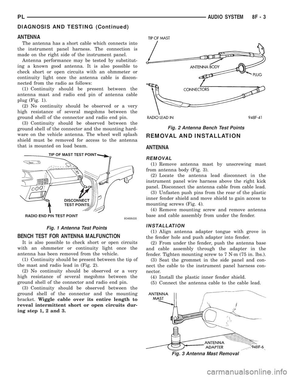
ANTENNA
The antenna has a short cable which connects into
the instrument panel harness. The connection is
made on the right side of the instrument panel.
Antenna performance may be tested by substitut-
ing a known good antenna. It is also possible to
check short or open circuits with an ohmmeter or
continuity light once the antenna cable is discon-
nected from the radio as follows:
(1) Continuity should be present between the
antenna mast and radio end pin of antenna cable
plug (Fig. 1).
(2) No continuity should be observed or a very
high resistance of several megohms between the
ground shell of the connector and radio end pin.
(3) Continuity should be observed between the
ground shell of the connector and the mounting hard-
ware on the vehicle antenna. The wheel well splash
shield must be removed for access to the antenna
that is mounted on load beam.
BENCH TEST FOR ANTENNA MALFUNCTION
It is also possible to check short or open circuits
with an ohmmeter or continuity light once the
antenna has been removed from the vehicle.
(1) Continuity should be present between the tip of
the mast and radio lead in (Fig. 2).
(2) No continuity should be observed or a very
high resistance of several megohms between the
ground shell of the connector and radio end pin.
(3) Continuity should be observed between the
ground shell of the connector and the mounting
bracket.Wiggle cable over its entire length to
reveal intermittent short or open circuits dur-
ing step 1, 2 and 3.
REMOVAL AND INSTALLATION
ANTENNA
REMOVAL
(1) Remove antenna mast by unscrewing mast
from antenna body (Fig. 3).
(2) Locate the antenna lead disconnect in the
instrument panel wire harness above the right kick
panel. Disconnect the antenna cable from cable lead.
(3) Unfasten push pins from the rear of the plastic
inner fender shield and move shield to gain access to
mounting screws (Fig. 4).
(4) Remove mounting screw and remove antenna
base and cable assembly from under the fender.
INSTALLATION
(1) Align antenna adapter tongue with grove in
the fender hole and push adapter into fender.
(2) From under the fender, push the antenna base
and cable assembly through the adapter in the
fender. Tighten mounting screw to 7 N´m (75 in. lbs.).
(3) Seat the grommet in the side panel and con-
nect the cable to the instrument panel harness con-
nector.
(4) Install the plastic inner fender shield.
(5) Connect the antenna cable to the cable lead.
Fig. 2 Antenna Bench Test Points
Fig. 3 Antenna Mast Removal
Fig. 1 Antenna Test Points
PLAUDIO SYSTEM 8F - 3
DIAGNOSIS AND TESTING (Continued)