DODGE NEON 2000 Service Repair Manual
Manufacturer: DODGE, Model Year: 2000, Model line: NEON, Model: DODGE NEON 2000Pages: 1285, PDF Size: 29.42 MB
Page 741 of 1285
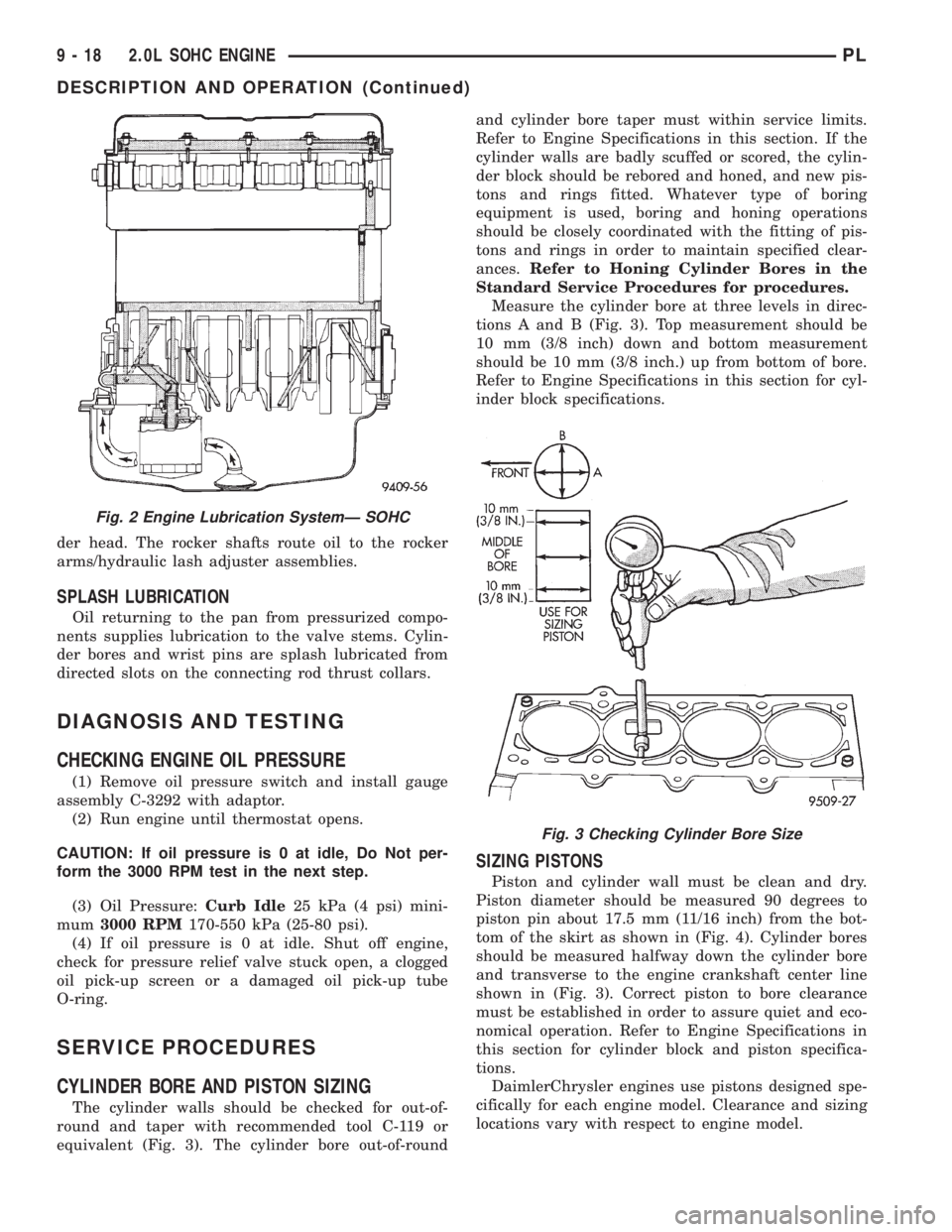
der head. The rocker shafts route oil to the rocker
arms/hydraulic lash adjuster assemblies.
SPLASH LUBRICATION
Oil returning to the pan from pressurized compo-
nents supplies lubrication to the valve stems. Cylin-
der bores and wrist pins are splash lubricated from
directed slots on the connecting rod thrust collars.
DIAGNOSIS AND TESTING
CHECKING ENGINE OIL PRESSURE
(1) Remove oil pressure switch and install gauge
assembly C-3292 with adaptor.
(2) Run engine until thermostat opens.
CAUTION: If oil pressure is 0 at idle, Do Not per-
form the 3000 RPM test in the next step.
(3) Oil Pressure:Curb Idle25 kPa (4 psi) mini-
mum3000 RPM170-550 kPa (25-80 psi).
(4) If oil pressure is 0 at idle. Shut off engine,
check for pressure relief valve stuck open, a clogged
oil pick-up screen or a damaged oil pick-up tube
O-ring.
SERVICE PROCEDURES
CYLINDER BORE AND PISTON SIZING
The cylinder walls should be checked for out-of-
round and taper with recommended tool C-119 or
equivalent (Fig. 3). The cylinder bore out-of-roundand cylinder bore taper must within service limits.
Refer to Engine Specifications in this section. If the
cylinder walls are badly scuffed or scored, the cylin-
der block should be rebored and honed, and new pis-
tons and rings fitted. Whatever type of boring
equipment is used, boring and honing operations
should be closely coordinated with the fitting of pis-
tons and rings in order to maintain specified clear-
ances.Refer to Honing Cylinder Bores in the
Standard Service Procedures for procedures.
Measure the cylinder bore at three levels in direc-
tions A and B (Fig. 3). Top measurement should be
10 mm (3/8 inch) down and bottom measurement
should be 10 mm (3/8 inch.) up from bottom of bore.
Refer to Engine Specifications in this section for cyl-
inder block specifications.
SIZING PISTONS
Piston and cylinder wall must be clean and dry.
Piston diameter should be measured 90 degrees to
piston pin about 17.5 mm (11/16 inch) from the bot-
tom of the skirt as shown in (Fig. 4). Cylinder bores
should be measured halfway down the cylinder bore
and transverse to the engine crankshaft center line
shown in (Fig. 3). Correct piston to bore clearance
must be established in order to assure quiet and eco-
nomical operation. Refer to Engine Specifications in
this section for cylinder block and piston specifica-
tions.
DaimlerChrysler engines use pistons designed spe-
cifically for each engine model. Clearance and sizing
locations vary with respect to engine model.
Fig. 2 Engine Lubrication SystemÐ SOHC
Fig. 3 Checking Cylinder Bore Size
9 - 18 2.0L SOHC ENGINEPL
DESCRIPTION AND OPERATION (Continued)
Page 742 of 1285
NOTE: Pistons and cylinder bores should be mea-
sured at normal room temperature, 21ÉC (70ÉF).
FITTING PISTON RINGS
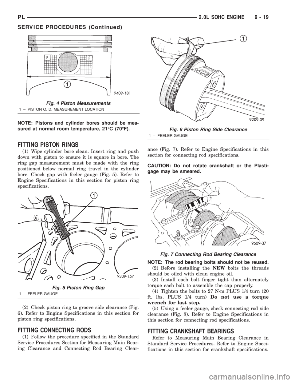
(1) Wipe cylinder bore clean. Insert ring and push
down with piston to ensure it is square in bore. The
ring gap measurement must be made with the ring
positioned below normal ring travel in the cylinder
bore. Check gap with feeler gauge (Fig. 5). Refer to
Engine Specifications in this section for piston ring
specifications.
(2) Check piston ring to groove side clearance (Fig.
6). Refer to Engine Specifications in this section for
piston ring specifications.
FITTING CONNECTING RODS
(1) Follow the procedure specified in the Standard
Service Procedures Section for Measuring Main Bear-
ing Clearance and Connecting Rod Bearing Clear-ance (Fig. 7). Refer to Engine Specifications in this
section for connecting rod specifications.
CAUTION: Do not rotate crankshaft or the Plasti-
gage may be smeared.
NOTE: The rod bearing bolts should not be reused.
(2) Before installing theNEWbolts the threads
should be oiled with clean engine oil.
(3) Install each bolt finger tight than alternately
torque each bolt to assemble the cap properly.
(4) Tighten the bolts to 27 N´m PLUS 1/4 turn (20
ft. lbs. PLUS 1/4 turn)Do not use a torque
wrench for last step.
(5) Using a feeler gauge, check connecting rod side
clearance (Fig. 8). Refer to Engine Specifications in
this section for connecting rod specifications.
FITTING CRANKSHAFT BEARINGS
Refer to Measuring Main Bearing Clearance in
Standard Service Procedures. Refer to Engine Speci-
fications in this section for crankshaft specifications.
Fig. 4 Piston Measurements
1 ± PISTON O. D. MEASUREMENT LOCATION
Fig. 5 Piston Ring Gap
1 ± FEELER GAUGE
Fig. 6 Piston Ring Side Clearance
1 ± FEELER GAUGE
Fig. 7 Connecting Rod Bearing Clearance
PL2.0L SOHC ENGINE 9 - 19
SERVICE PROCEDURES (Continued)
Page 743 of 1285
CRANKSHAFT END PLAY
DIAL INDICATOR METHOD
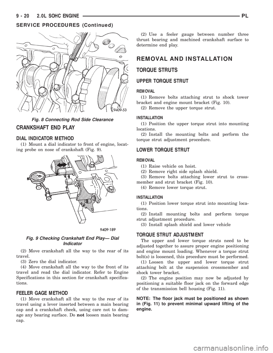
(1) Mount a dial indicator to front of engine, locat-
ing probe on nose of crankshaft (Fig. 9).
(2) Move crankshaft all the way to the rear of its
travel.
(3) Zero the dial indicator.
(4) Move crankshaft all the way to the front of its
travel and read the dial indicator. Refer to Engine
Specifications in this section for crankshaft specifica-
tions.
FEELER GAGE METHOD
(1) Move crankshaft all the way to the rear of its
travel using a lever inserted between a main bearing
cap and a crankshaft cheek, using care not to dam-
age any bearing surface. Donotloosen main bearing
cap.(2) Use a feeler gauge between number three
thrust bearing and machined crankshaft surface to
determine end play.
REMOVAL AND INSTALLATION
TORQUE STRUTS
UPPER TORQUE STRUT
REMOVAL
(1) Remove bolts attaching strut to shock tower
bracket and engine mount bracket (Fig. 10).
(2) Remove the upper torque strut.
INSTALLATION
(1) Position the upper torque strut into mounting
locations.
(2) Install the mounting bolts and perform the
torque strut adjustment procedure.
LOWER TORQUE STRUT
REMOVAL
(1) Raise vehicle on hoist.
(2) Remove right side splash shield.
(3) Remove bolts attaching lower strut to cross-
member and strut bracket (Fig. 10).
(4) Remove lower torque strut.
INSTALLATION
(1) Position lower torque strut into mounting loca-
tions.
(2) Install mounting bolts and perform torque
strut adjustment procedure.
(3) Install splash shield and lower vehicle
TORQUE STRUT ADJUSTMENT
The upper and lower torque struts need to be
adjusted together to assure proper engine positioning
and engine mount loading. Whenever a torque strut
bolt(s) is loosened, this procedure must be performed.
(1) Loosen the upper and lower torque strut
attaching bolt at the suspension crossmember and
shock tower bracket.
(2) The engine position may now be adjusted by
positioning a suitable floor jack on the forward edge
of the transmission bell housing (Fig. 11).
NOTE: The floor jack must be positioned as shown
in (Fig. 11) to prevent minimal upward lifting of the
engine.
Fig. 8 Connecting Rod Side Clearance
Fig. 9 Checking Crankshaft End PlayÐ Dial
Indicator
9 - 20 2.0L SOHC ENGINEPL
SERVICE PROCEDURES (Continued)
Page 744 of 1285
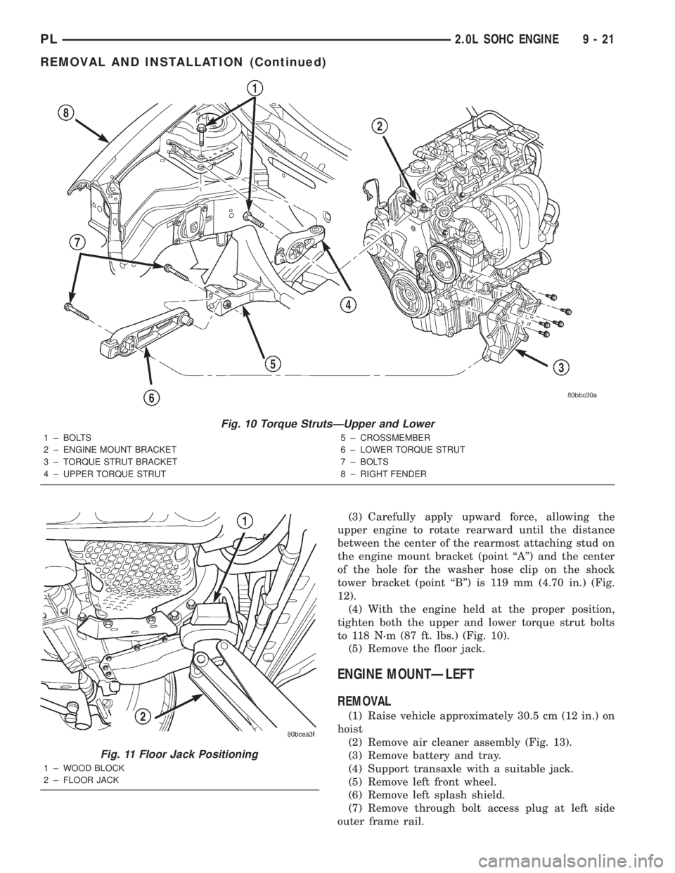
(3) Carefully apply upward force, allowing the
upper engine to rotate rearward until the distance
between the center of the rearmost attaching stud on
the engine mount bracket (point ªAº) and the center
of the hole for the washer hose clip on the shock
tower bracket (point ªBº) is 119 mm (4.70 in.) (Fig.
12).
(4) With the engine held at the proper position,
tighten both the upper and lower torque strut bolts
to 118 N´m (87 ft. lbs.) (Fig. 10).
(5) Remove the floor jack.
ENGINE MOUNTÐLEFT
REMOVAL
(1) Raise vehicle approximately 30.5 cm (12 in.) on
hoist
(2) Remove air cleaner assembly (Fig. 13).
(3) Remove battery and tray.
(4) Support transaxle with a suitable jack.
(5) Remove left front wheel.
(6) Remove left splash shield.
(7) Remove through bolt access plug at left side
outer frame rail.
Fig. 10 Torque StrutsÐUpper and Lower
1 ± BOLTS
2 ± ENGINE MOUNT BRACKET
3 ± TORQUE STRUT BRACKET
4 ± UPPER TORQUE STRUT5 ± CROSSMEMBER
6 ± LOWER TORQUE STRUT
7 ± BOLTS
8 ± RIGHT FENDER
Fig. 11 Floor Jack Positioning
1 ± WOOD BLOCK
2 ± FLOOR JACK
PL2.0L SOHC ENGINE 9 - 21
REMOVAL AND INSTALLATION (Continued)
Page 745 of 1285
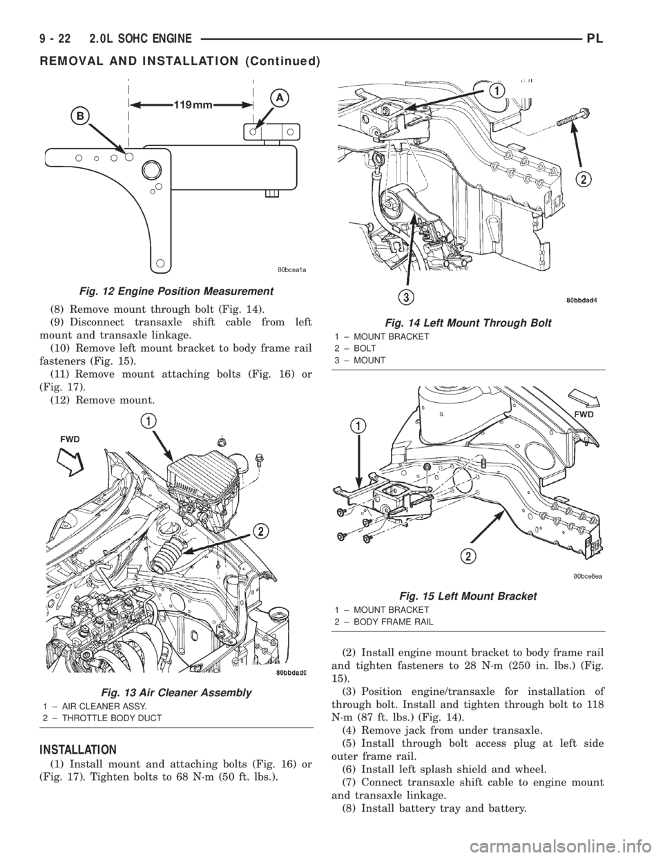
(8) Remove mount through bolt (Fig. 14).
(9) Disconnect transaxle shift cable from left
mount and transaxle linkage.
(10) Remove left mount bracket to body frame rail
fasteners (Fig. 15).
(11) Remove mount attaching bolts (Fig. 16) or
(Fig. 17).
(12) Remove mount.
INSTALLATION
(1) Install mount and attaching bolts (Fig. 16) or
(Fig. 17). Tighten bolts to 68 N´m (50 ft. lbs.).(2) Install engine mount bracket to body frame rail
and tighten fasteners to 28 N´m (250 in. lbs.) (Fig.
15).
(3) Position engine/transaxle for installation of
through bolt. Install and tighten through bolt to 118
N´m (87 ft. lbs.) (Fig. 14).
(4) Remove jack from under transaxle.
(5) Install through bolt access plug at left side
outer frame rail.
(6) Install left splash shield and wheel.
(7) Connect transaxle shift cable to engine mount
and transaxle linkage.
(8) Install battery tray and battery.
Fig. 12 Engine Position Measurement
Fig. 13 Air Cleaner Assembly
1 ± AIR CLEANER ASSY.
2 ± THROTTLE BODY DUCT
Fig. 14 Left Mount Through Bolt
1 ± MOUNT BRACKET
2 ± BOLT
3 ± MOUNT
Fig. 15 Left Mount Bracket
1 ± MOUNT BRACKET
2 ± BODY FRAME RAIL
9 - 22 2.0L SOHC ENGINEPL
REMOVAL AND INSTALLATION (Continued)
Page 746 of 1285
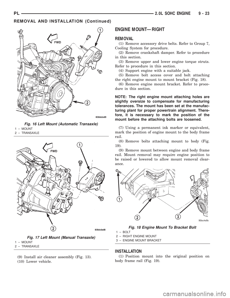
(9) Install air cleaner assembly (Fig. 13).
(10) Lower vehicle.
ENGINE MOUNTÐRIGHT
REMOVAL
(1) Remove accessory drive belts. Refer to Group 7,
Cooling System for procedure.
(2) Remove crankshaft damper. Refer to procedure
in this section.
(3) Remove upper and lower engine torque struts.
Refer to procedure in this section.
(4) Support engine with a suitable jack.
(5) Remove bolt access cover and bolt attaching
the right engine mount to mount bracket (Fig. 18).
(6) Remove engine mount bracket. Refer to proce-
dure in this section.
NOTE: The right engine mount attaching holes are
slightly oversize to compensate for manufacturing
tolerances. The mount has been set at the manufac-
turing plant for proper powertrain alignment. There-
fore, it is necessary to mark the position of the
mount before the attaching bolts are loosened.
(7) Using a permanent ink marker or equivalent,
mark the position of engine mount to the body frame
rail.
(8) Remove bolts attaching mount to body (Fig.
19).
(9) Remove mount between engine and body frame
rail. Mount removal may require engine position to
be raised or lowered to allow mount removal clear-
ance.
INSTALLATION
(1) Position mount into the original position on
body frame rail (Fig. 19).
Fig. 16 Left Mount (Automatic Transaxle)
1 ± MOUNT
2 ± TRANSAXLE
Fig. 17 Left Mount (Manual Transaxle)
1 ± MOUNT
2 ± TRANSAXLE
Fig. 18 Engine Mount To Bracket Bolt
1 ± BOLT
2 ± RIGHT ENGINE MOUNT
3 ± ENGINE MOUNT BRACKET
PL2.0L SOHC ENGINE 9 - 23
REMOVAL AND INSTALLATION (Continued)
Page 747 of 1285
NOTE: Engine mount must be installed in the orig-
inal position on body frame rail. If mount was not
marked or frame rail was replaced, perform the fol-
lowing procedure.
(2) Perform the following procedure if mount posi-
tion was not previously marked or the frame rail was
replaced:
a. Insert new mount loosely in frame rail.
b. Align the four holes in the mount with the mat-
ing holes in the rail such that the holes are concen-
tric (frame rail holes centered in the mount holes).
c. Using a permanent ink marker or equivalent,
mark the position of engine mount to the body frame
rail while maintaining mounting hole concentricity.
(3) Ensure the mount maintains originally marked
position and install mount bolts. Tighten bolts to 28
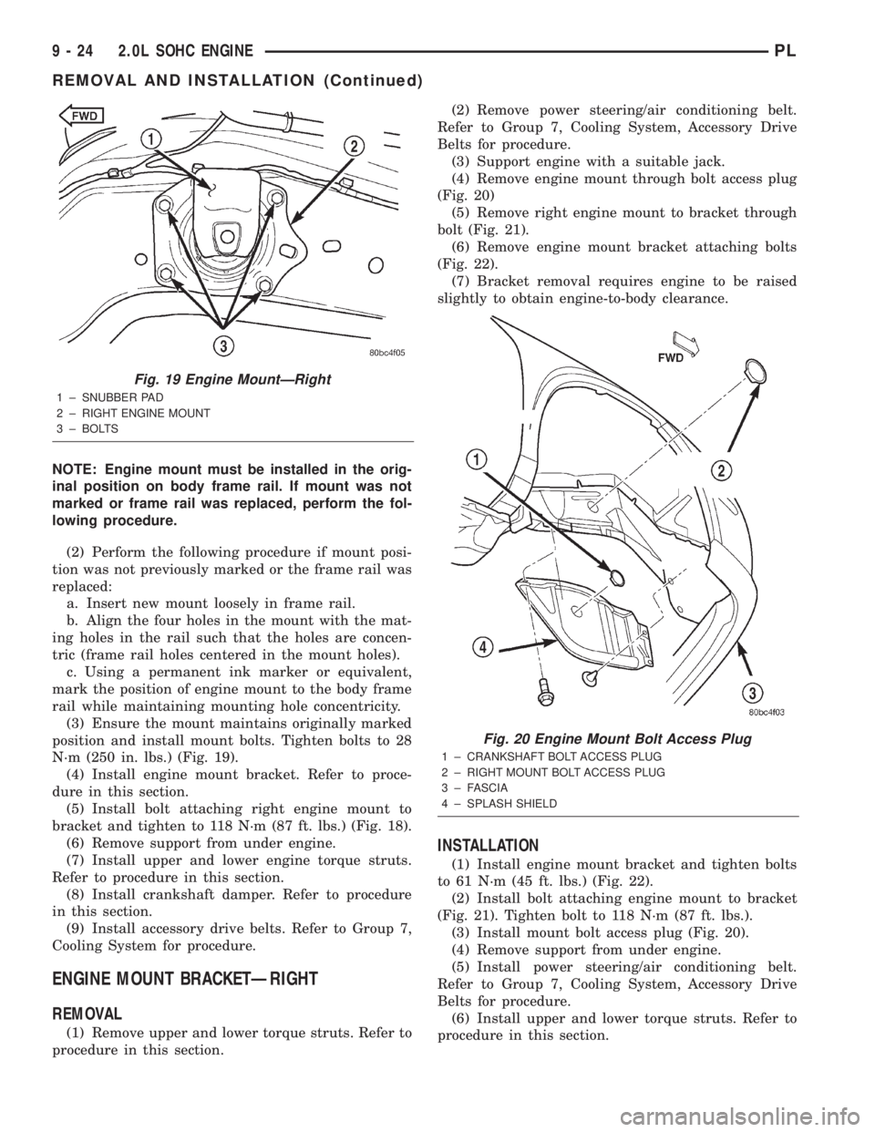
N´m (250 in. lbs.) (Fig. 19).
(4) Install engine mount bracket. Refer to proce-
dure in this section.
(5) Install bolt attaching right engine mount to
bracket and tighten to 118 N´m (87 ft. lbs.) (Fig. 18).
(6) Remove support from under engine.
(7) Install upper and lower engine torque struts.
Refer to procedure in this section.
(8) Install crankshaft damper. Refer to procedure
in this section.
(9) Install accessory drive belts. Refer to Group 7,
Cooling System for procedure.
ENGINE MOUNT BRACKETÐRIGHT
REMOVAL
(1) Remove upper and lower torque struts. Refer to
procedure in this section.(2) Remove power steering/air conditioning belt.
Refer to Group 7, Cooling System, Accessory Drive
Belts for procedure.
(3) Support engine with a suitable jack.
(4) Remove engine mount through bolt access plug
(Fig. 20)
(5) Remove right engine mount to bracket through
bolt (Fig. 21).
(6) Remove engine mount bracket attaching bolts
(Fig. 22).
(7) Bracket removal requires engine to be raised
slightly to obtain engine-to-body clearance.
INSTALLATION
(1) Install engine mount bracket and tighten bolts
to 61 N´m (45 ft. lbs.) (Fig. 22).
(2) Install bolt attaching engine mount to bracket
(Fig. 21). Tighten bolt to 118 N´m (87 ft. lbs.).
(3) Install mount bolt access plug (Fig. 20).
(4) Remove support from under engine.
(5) Install power steering/air conditioning belt.
Refer to Group 7, Cooling System, Accessory Drive
Belts for procedure.
(6) Install upper and lower torque struts. Refer to
procedure in this section.
Fig. 19 Engine MountÐRight
1 ± SNUBBER PAD
2 ± RIGHT ENGINE MOUNT
3 ± BOLTS
Fig. 20 Engine Mount Bolt Access Plug
1 ± CRANKSHAFT BOLT ACCESS PLUG
2 ± RIGHT MOUNT BOLT ACCESS PLUG
3 ± FASCIA
4 ± SPLASH SHIELD
9 - 24 2.0L SOHC ENGINEPL
REMOVAL AND INSTALLATION (Continued)
Page 748 of 1285
STRUCTURAL COLLAR
REMOVAL
(1) Raise vehicle on hoist.NOTE: To remove transaxle dust cover, the front
bending strut must be removed.
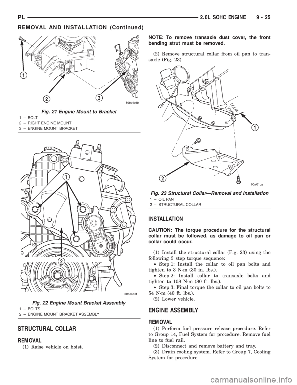
(2) Remove structural collar from oil pan to tran-
saxle (Fig. 23).
INSTALLATION
CAUTION: The torque procedure for the structural
collar must be followed, as damage to oil pan or
collar could occur.
(1) Install the structural collar (Fig. 23) using the
following 3 step torque sequence:
²Step 1: Install the collar to oil pan bolts and
tighten to 3 N´m (30 in. lbs.).
²Step 2: Install collar to transaxle bolts and
tighten to 108 N´m (80 ft. lbs.).
²Step 3: Final torque the collar to oil pan bolts to
54 N´m (40 ft. lbs.).
(2) Lower vehicle.
ENGINE ASSEMBLY
REMOVAL
(1) Perform fuel pressure release procedure. Refer
to Group 14, Fuel System for procedure. Remove fuel
line to fuel rail.
(2) Disconnect and remove battery and tray.
(3) Drain cooling system. Refer to Group 7, Cooling
System for procedure.
Fig. 21 Engine Mount to Bracket
1 ± BOLT
2 ± RIGHT ENGINE MOUNT
3 ± ENGINE MOUNT BRACKET
Fig. 22 Engine Mount Bracket Assembly
1 ± BOLTS
2 ± ENGINE MOUNT BRACKET ASSEMBLY
Fig. 23 Structural CollarÐRemoval and Installation
1 ± OIL PAN
2 ± STRUCTURAL COLLAR
PL2.0L SOHC ENGINE 9 - 25
REMOVAL AND INSTALLATION (Continued)
Page 749 of 1285
(4) Discharge air conditioning system, if equipped.
Refer to Group 24, Heating and Air Conditioning for
procedure.
(5) Disconnect the following: air intake duct at
intake manifold, throttle cables, electrical connectors
from throttle body and air cleaner housing.
(6) Remove air cleaner housing assembly.
(7) Remove upper radiator hose and fan module.
Refer to Group 7, Cooling System for procedure.
(8) Remove lower radiator hose.
(9) Disconnect automatic transmission cooler lines
and plug, if equipped.
(10) Disconnect shift linkage, electrical connectors,
and clutch cable, if equipped with manual transaxle.
(11) Disconnect engine wiring harness.
(12) Disconnect positive cable from Power Distri-
bution Center (PDC) and ground wire from vehicle
body.
(13) Disconnect ground wire from the vehicle body-
to-engine at the right side strut tower.
(14) Disconnect heater hoses.
(15) Disconnect vacuum hose from brake booster.
(16) Disconnect coolant reserve/recovery hose.
(17) Remove accessory drive belts. Refer to Group
7, Cooling System for procedure.
(18) Remove power steering pump and reservoir
and set them aside.
(19) Hoist vehicle and remove right inner splash
shield.
(20) Drain engine oil.
(21) Remove front wheels.
(22) Remove axle shafts. Refer to Group 3, Differ-
ential and Driveline for procedure.
(23) Disconnect exhaust system from manifold.
(24) Disconnect the downstream oxygen sensor
connector.
(25) Remove lower engine torque strut.
(26) Remove structural collar. Refer to procedure
in this section.
(27) Lower vehicle and remove A/C compressor.
(28) Raise vehicle enough to allow engine dolly
and cradle, Special Tools 6135 and 6710 to be
installed under vehicle.
(29) Loosen engine support posts to allow move-
ment for positioning onto engine locating holes and
flange on the engine bedplate. Lower vehicle and
position cradle until the engine is resting on support
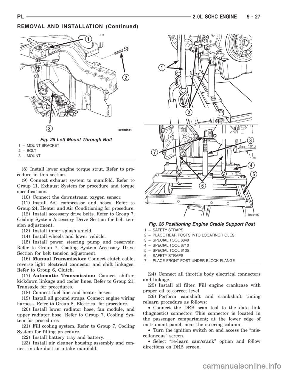
posts (Fig. 26). Tighten mounts to cradle frame. This
will keep support posts from moving when removing
or installing engine and transmission.
(30) Install safety straps around the engine to cra-
dle (Fig. 26). Tighten straps and lock them into posi-
tion.
WARNING: Safety straps MUST be used.(31) Raise vehicle enough to see if straps are tight
enough to hold cradle assembly to engine.
(32) Lower vehicle so weight of the engine and
transmission ONLY is on the cradle assembly.
(33) Remove the upper engine torque strut.
(34) Remove right and left engine and transaxle
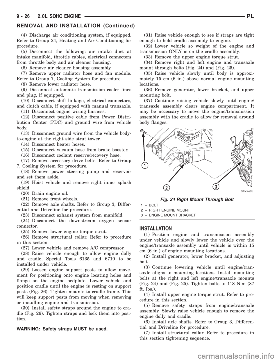
mount through bolts (Fig. 24) and (Fig. 25).
(35) Raise vehicle slowly until body is approxi-
mately 15 cm (6 in.) above normal engine mounting
locations.
(36) Remove generator, lower bracket, and upper
mounting bolt.
(37) Continue raising vehicle slowly until engine/
transaxle assembly clears engine compartment. It
may be necessary to move the engine/transmission
assembly with the cradle to allow for removal around
body flanges.
INSTALLATION
(1) Position engine and transmission assembly
under vehicle and slowly lower the vehicle over the
engine/transaxle assembly until vehicle is within 15
cm (6 in.) of engine mounting locations.
(2) Install generator, lower bracket, and adjusting
bolt.
(3) Continue lowering vehicle until engine/tran-
saxle aligns to mounting locations. Install mounting
bolts at the right and left engine/transaxle mounts
(Fig. 24) and (Fig. 25). Tighten bolts to 118 N´m (87
ft. lbs.).
(4) Install upper engine torque strut. Refer to pro-
cedure in this section.
(5) Remove safety straps from engine/transaxle
assembly. Slowly raise vehicle enough to remove the
engine dolly and cradle.
(6) Install axle shafts. Refer to Group 3, Differen-
tial and Driveline for procedure.
(7) Install structural collar. Refer to procedure in
this section tightening sequence.
Fig. 24 Right Mount Through Bolt
1 ± BOLT
2 ± RIGHT ENGINE MOUNT
3 ± ENGINE MOUNT BRACKET
9 - 26 2.0L SOHC ENGINEPL
REMOVAL AND INSTALLATION (Continued)
Page 750 of 1285
(8) Install lower engine torque strut. Refer to pro-
cedure in this section.
(9) Connect exhaust system to manifold. Refer to
Group 11, Exhaust System for procedure and torque
specifications.
(10) Connect the downstream oxygen sensor.
(11) Install A/C compressor and hoses. Refer to
Group 24, Heater and Air Conditioning for procedure.
(12) Install accessory drive belts. Refer to Group 7,
Cooling System Accessory Drive Section for belt ten-
sion adjustment.
(13) Install inner splash shield.
(14) Install wheels and lower vehicle.
(15) Install power steering pump and reservoir.
Refer to Group 7, Cooling System Accessory Drive
Section for belt tension adjustment.
(16)Manual Transmission:Connect clutch cable,
reverse light electrical connector and shift linkages.
Refer to Group 6, Clutch.
(17)Automatic Transmission:Connect shifter,
kickdown linkage and cooler lines. Refer to Group 21,
Transaxle for procedures.
(18) Connect fuel line and heater hoses.
(19)
Install all ground straps. Connect engine wiring
harness. Refer to Group 8, Electrical for procedure.
(20) Install lower radiator hose, fan module, and
upper radiator hose. Refer to Group 7, Cooling Sys-
tem for procedures
(21) Fill cooling system. Refer to Group 7, Cooling
System for filling procedure.
(22) Install battery tray and battery.
(23) Install air cleaner housing assembly and con-
nect intake duct to intake manifold.(24) Connect all throttle body electrical connectors
and linkage.
(25) Install oil filter. Fill engine crankcase with
proper oil to correct level.
(26) Perform camshaft and crankshaft timing
relearn procedure as follows:
²Connect the DRB scan tool to the data link
(diagnostic) connector. This connector is located in
the passenger compartment; at the lower edge of
instrument panel; near the steering column.
²Turn the ignition switch on and access the ªmis-
cellaneousº screen.
²Select ªre-learn cam/crankº option and follow
directions on DRB screen.
Fig. 25 Left Mount Through Bolt
1 ± MOUNT BRACKET
2 ± BOLT
3 ± MOUNT
Fig. 26 Positioning Engine Cradle Support Post
1 ± SAFETY STRAPS
2 ± PLACE REAR POSTS INTO LOCATING HOLES
3 ± SPECIAL TOOL 6848
4 ± SPECIAL TOOL 6710
5 ± SPECIAL TOOL 6135
6 ± SAFETY STRAPS
7 ± PLACE FRONT POST UNDER BLOCK FLANGE
PL2.0L SOHC ENGINE 9 - 27
REMOVAL AND INSTALLATION (Continued)