DODGE RAM 2001 Service Repair Manual
Manufacturer: DODGE, Model Year: 2001, Model line: RAM, Model: DODGE RAM 2001Pages: 2889, PDF Size: 68.07 MB
Page 2341 of 2889
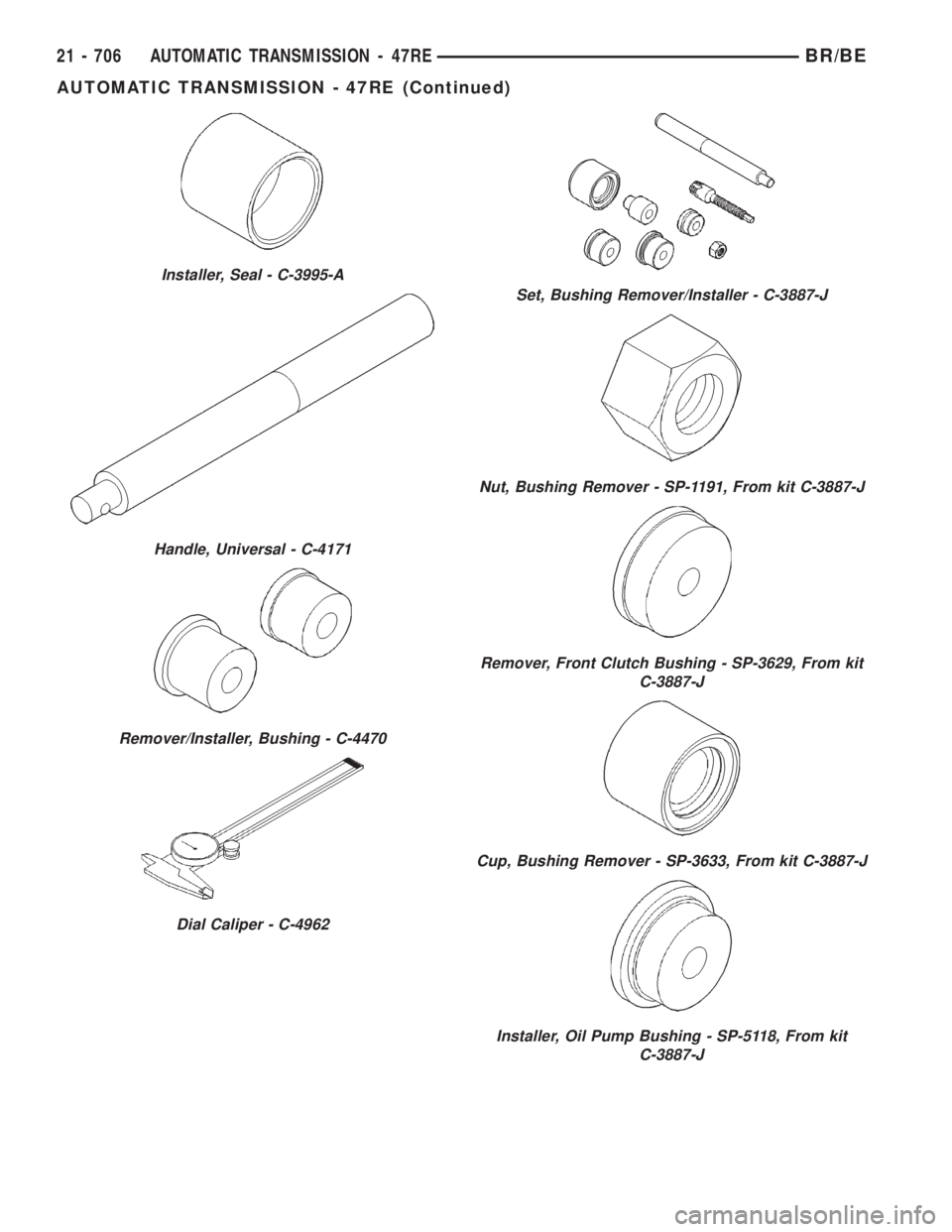
Installer, Seal - C-3995-A
Handle, Universal - C-4171
Remover/Installer, Bushing - C-4470
Dial Caliper - C-4962
Set, Bushing Remover/Installer - C-3887-J
Nut, Bushing Remover - SP-1191, From kit C-3887-J
Remover, Front Clutch Bushing - SP-3629, From kit
C-3887-J
Cup, Bushing Remover - SP-3633, From kit C-3887-J
Installer, Oil Pump Bushing - SP-5118, From kit
C-3887-J
21 - 706 AUTOMATIC TRANSMISSION - 47REBR/BE
AUTOMATIC TRANSMISSION - 47RE (Continued)
Page 2342 of 2889
ACCUMULATOR
DESCRIPTION
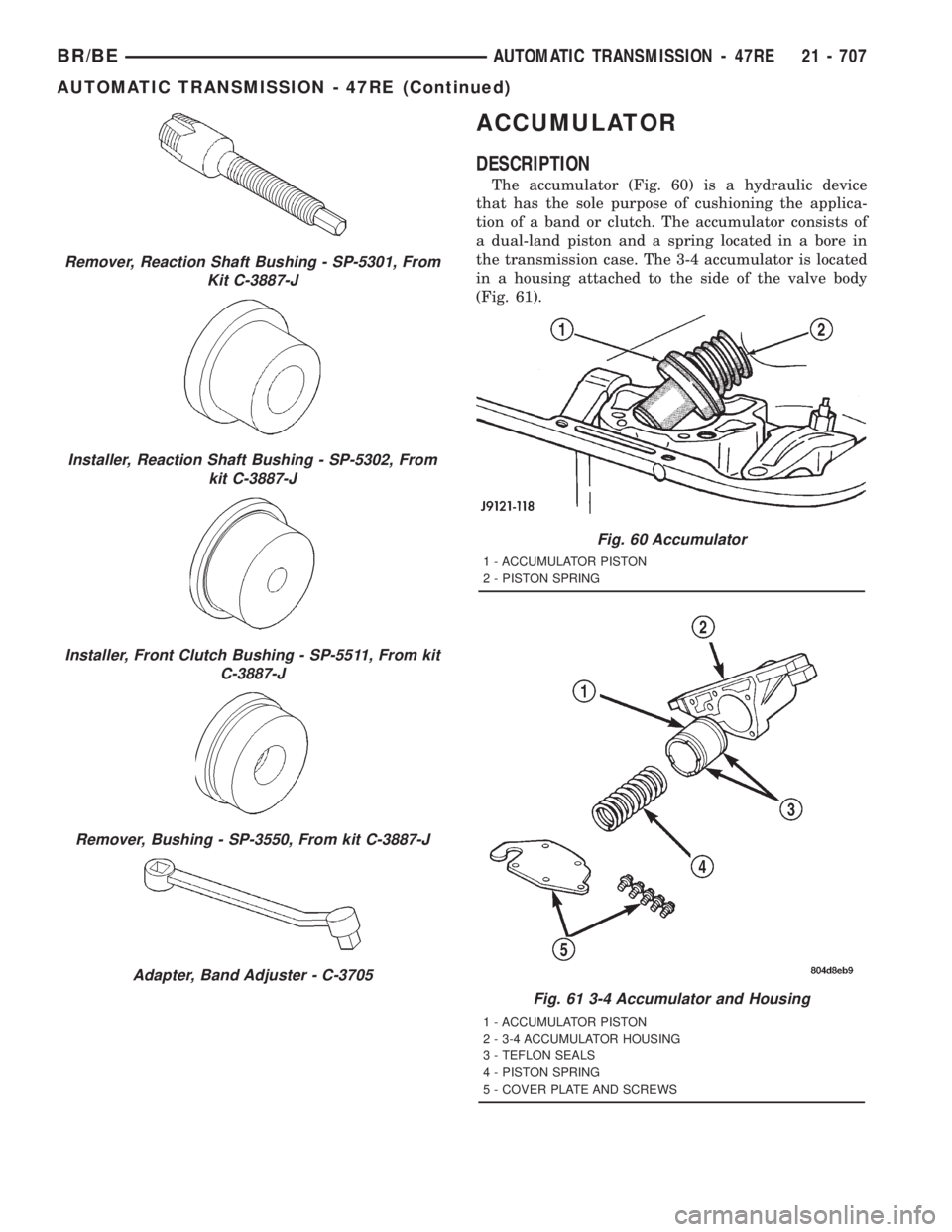
The accumulator (Fig. 60) is a hydraulic device
that has the sole purpose of cushioning the applica-
tion of a band or clutch. The accumulator consists of
a dual-land piston and a spring located in a bore in
the transmission case. The 3-4 accumulator is located
in a housing attached to the side of the valve body
(Fig. 61).
Remover, Reaction Shaft Bushing - SP-5301, From
Kit C-3887-J
Installer, Reaction Shaft Bushing - SP-5302, From
kit C-3887-J
Installer, Front Clutch Bushing - SP-5511, From kit
C-3887-J
Remover, Bushing - SP-3550, From kit C-3887-J
Adapter, Band Adjuster - C-3705
Fig. 60 Accumulator
1 - ACCUMULATOR PISTON
2 - PISTON SPRING
Fig. 61 3-4 Accumulator and Housing
1 - ACCUMULATOR PISTON
2 - 3-4 ACCUMULATOR HOUSING
3 - TEFLON SEALS
4 - PISTON SPRING
5 - COVER PLATE AND SCREWS
BR/BEAUTOMATIC TRANSMISSION - 47RE 21 - 707
AUTOMATIC TRANSMISSION - 47RE (Continued)
Page 2343 of 2889
OPERATION
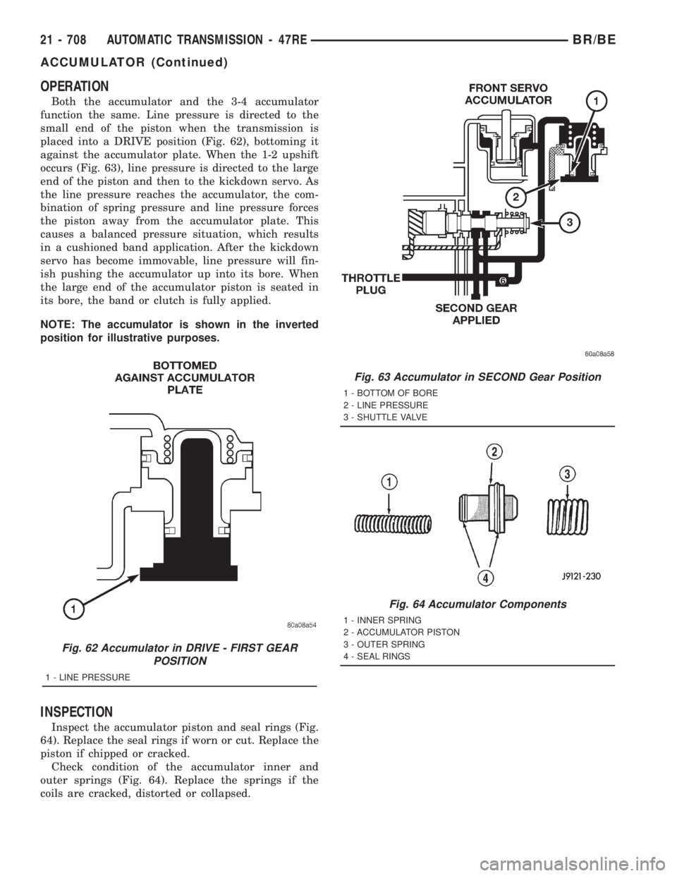
Both the accumulator and the 3-4 accumulator
function the same. Line pressure is directed to the
small end of the piston when the transmission is
placed into a DRIVE position (Fig. 62), bottoming it
against the accumulator plate. When the 1-2 upshift
occurs (Fig. 63), line pressure is directed to the large
end of the piston and then to the kickdown servo. As
the line pressure reaches the accumulator, the com-
bination of spring pressure and line pressure forces
the piston away from the accumulator plate. This
causes a balanced pressure situation, which results
in a cushioned band application. After the kickdown
servo has become immovable, line pressure will fin-
ish pushing the accumulator up into its bore. When
the large end of the accumulator piston is seated in
its bore, the band or clutch is fully applied.
NOTE: The accumulator is shown in the inverted
position for illustrative purposes.
INSPECTION
Inspect the accumulator piston and seal rings (Fig.
64). Replace the seal rings if worn or cut. Replace the
piston if chipped or cracked.
Check condition of the accumulator inner and
outer springs (Fig. 64). Replace the springs if the
coils are cracked, distorted or collapsed.
Fig. 62 Accumulator in DRIVE - FIRST GEAR
POSITION
1 - LINE PRESSURE
Fig. 63 Accumulator in SECOND Gear Position
1 - BOTTOM OF BORE
2 - LINE PRESSURE
3 - SHUTTLE VALVE
Fig. 64 Accumulator Components
1 - INNER SPRING
2 - ACCUMULATOR PISTON
3 - OUTER SPRING
4 - SEAL RINGS
21 - 708 AUTOMATIC TRANSMISSION - 47REBR/BE
ACCUMULATOR (Continued)
Page 2344 of 2889
BANDS
DESCRIPTION
KICKDOWN (FRONT) BAND
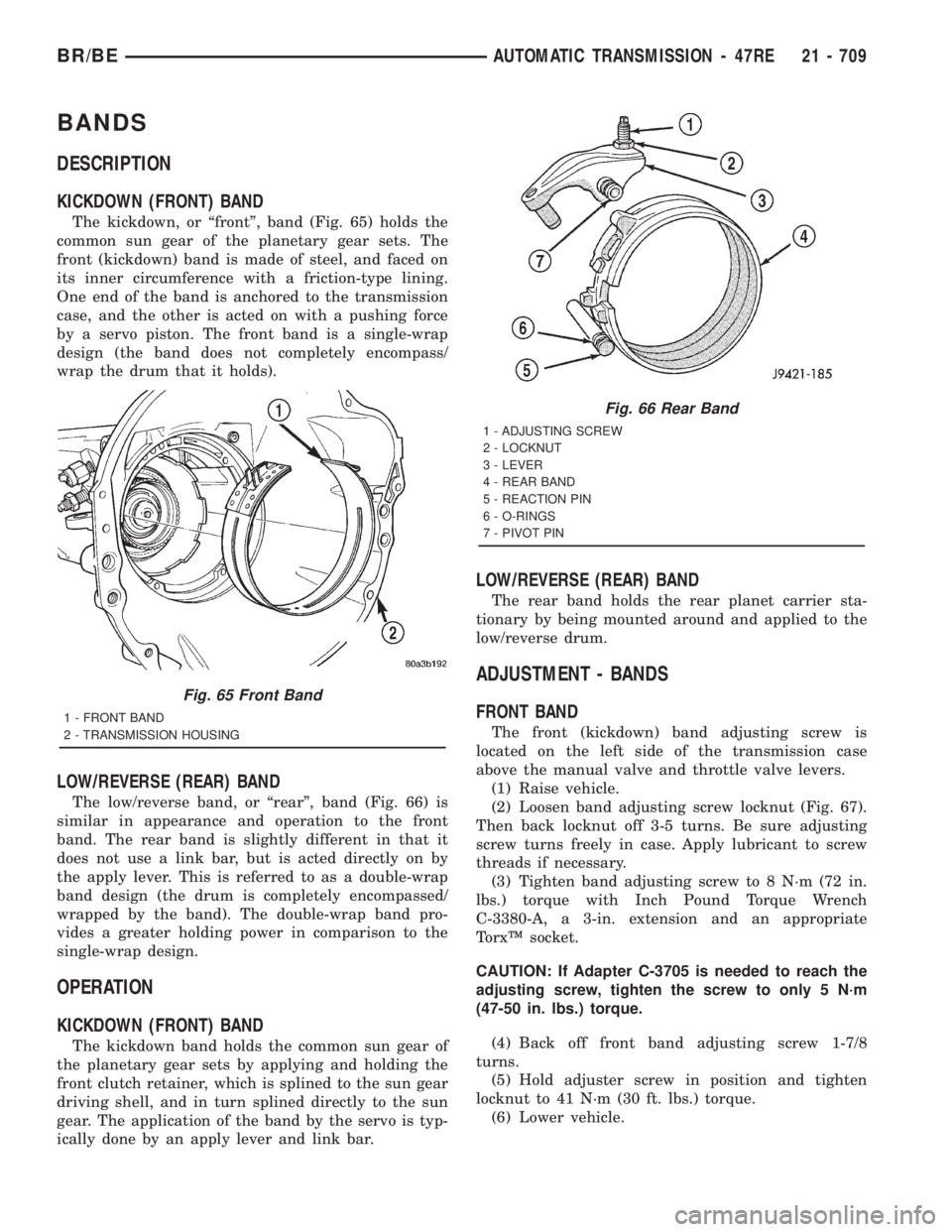
The kickdown, or ªfrontº, band (Fig. 65) holds the
common sun gear of the planetary gear sets. The
front (kickdown) band is made of steel, and faced on
its inner circumference with a friction-type lining.
One end of the band is anchored to the transmission
case, and the other is acted on with a pushing force
by a servo piston. The front band is a single-wrap
design (the band does not completely encompass/
wrap the drum that it holds).
LOW/REVERSE (REAR) BAND
The low/reverse band, or ªrearº, band (Fig. 66) is
similar in appearance and operation to the front
band. The rear band is slightly different in that it
does not use a link bar, but is acted directly on by
the apply lever. This is referred to as a double-wrap
band design (the drum is completely encompassed/
wrapped by the band). The double-wrap band pro-
vides a greater holding power in comparison to the
single-wrap design.
OPERATION
KICKDOWN (FRONT) BAND
The kickdown band holds the common sun gear of
the planetary gear sets by applying and holding the
front clutch retainer, which is splined to the sun gear
driving shell, and in turn splined directly to the sun
gear. The application of the band by the servo is typ-
ically done by an apply lever and link bar.
LOW/REVERSE (REAR) BAND
The rear band holds the rear planet carrier sta-
tionary by being mounted around and applied to the
low/reverse drum.
ADJUSTMENT - BANDS
FRONT BAND
The front (kickdown) band adjusting screw is
located on the left side of the transmission case
above the manual valve and throttle valve levers.
(1) Raise vehicle.
(2) Loosen band adjusting screw locknut (Fig. 67).
Then back locknut off 3-5 turns. Be sure adjusting
screw turns freely in case. Apply lubricant to screw
threads if necessary.
(3) Tighten band adjusting screw to 8 N´m (72 in.
lbs.) torque with Inch Pound Torque Wrench
C-3380-A, a 3-in. extension and an appropriate
TorxŸ socket.
CAUTION: If Adapter C-3705 is needed to reach the
adjusting screw, tighten the screw to only 5 N´m
(47-50 in. lbs.) torque.
(4) Back off front band adjusting screw 1-7/8
turns.
(5) Hold adjuster screw in position and tighten
locknut to 41 N´m (30 ft. lbs.) torque.
(6) Lower vehicle.
Fig. 65 Front Band
1 - FRONT BAND
2 - TRANSMISSION HOUSING
Fig. 66 Rear Band
1 - ADJUSTING SCREW
2 - LOCKNUT
3 - LEVER
4 - REAR BAND
5 - REACTION PIN
6 - O-RINGS
7 - PIVOT PIN
BR/BEAUTOMATIC TRANSMISSION - 47RE 21 - 709
Page 2345 of 2889
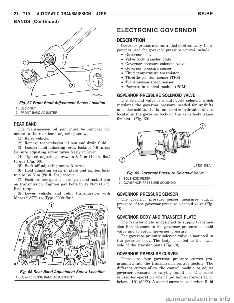
REAR BAND
The transmission oil pan must be removed for
access to the rear band adjusting screw.
(1) Raise vehicle.
(2) Remove transmission oil pan and drain fluid.
(3) Loosen band adjusting screw locknut 5-6 turns.
Be sure adjusting screw turns freely in lever.
(4) Tighten adjusting screw to 8 N´m (72 in. lbs.)
torque (Fig. 68).
(5) Back off adjusting screw 3 turns.
(6) Hold adjusting screw in place and tighten lock-
nut to 34 N´m (25 ft. lbs.) torque.
(7) Position new gasket on oil pan and install pan
on transmission. Tighten pan bolts to 17 N´m (13 ft.
lbs.) torque.
(8) Lower vehicle and refill transmission with
MopartATF +4, Type 9602 fluid.
ELECTRONIC GOVERNOR
DESCRIPTION
Governor pressure is controlled electronically. Com-
ponents used for governor pressure control include:
²Governor body
²Valve body transfer plate
²Governor pressure solenoid valve
²Governor pressure sensor
²Fluid temperature thermistor
²Throttle position sensor (TPS)
²Transmission speed sensor
²Powertrain control module (PCM)
GOVERNOR PRESSURE SOLENOID VALVE
The solenoid valve is a duty-cycle solenoid which
regulates the governor pressure needed for upshifts
and downshifts. It is an electro-hydraulic device
located in the governor body on the valve body trans-
fer plate (Fig. 69).
GOVERNOR PRESSURE SENSOR
The governor pressure sensor measures output
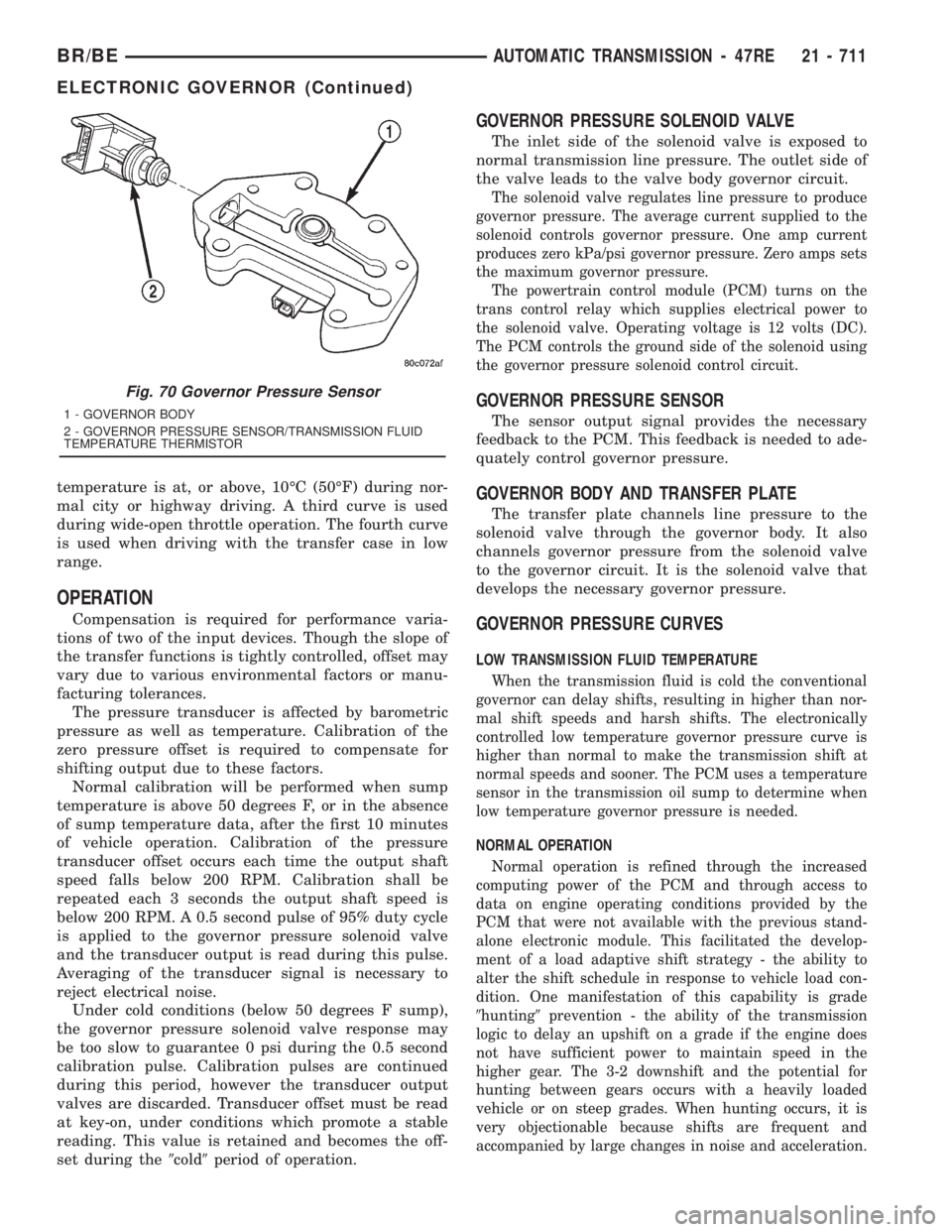
pressure of the governor pressure solenoid valve (Fig.
70).
GOVERNOR BODY AND TRANSFER PLATE
The transfer plate is designed to supply transmis-
sion line pressure to the governor pressure solenoid
valve and to return governor pressure.
The governor pressure solenoid valve is mounted in
the governor body. The body is bolted to the lower
side of the transfer plate (Fig. 70).
GOVERNOR PRESSURE CURVES
There are four governor pressure curves pro-
grammed into the transmission control module. The
different curves allow the control module to adjust
governor pressure for varying conditions. One curve
is used for operation when fluid temperature is at, or
below, ±1ÉC (30ÉF). A second curve is used when fluid
Fig. 67 Front Band Adjustment Screw Location
1 - LOCK-NUT
2 - FRONT BAND ADJUSTER
Fig. 68 Rear Band Adjustment Screw Location
1 - LOW-REVERSE BAND ADJUSTMENT
Fig. 69 Governor Pressure Solenoid Valve
1 - SOLENOID FILTER
2 - GOVERNOR PRESSURE SOLENOID
21 - 710 AUTOMATIC TRANSMISSION - 47REBR/BE
BANDS (Continued)
Page 2346 of 2889
temperature is at, or above, 10ÉC (50ÉF) during nor-
mal city or highway driving. A third curve is used
during wide-open throttle operation. The fourth curve
is used when driving with the transfer case in low
range.
OPERATION
Compensation is required for performance varia-
tions of two of the input devices. Though the slope of
the transfer functions is tightly controlled, offset may
vary due to various environmental factors or manu-
facturing tolerances.
The pressure transducer is affected by barometric
pressure as well as temperature. Calibration of the
zero pressure offset is required to compensate for
shifting output due to these factors.
Normal calibration will be performed when sump
temperature is above 50 degrees F, or in the absence
of sump temperature data, after the first 10 minutes
of vehicle operation. Calibration of the pressure
transducer offset occurs each time the output shaft
speed falls below 200 RPM. Calibration shall be
repeated each 3 seconds the output shaft speed is
below 200 RPM. A 0.5 second pulse of 95% duty cycle
is applied to the governor pressure solenoid valve
and the transducer output is read during this pulse.
Averaging of the transducer signal is necessary to
reject electrical noise.
Under cold conditions (below 50 degrees F sump),
the governor pressure solenoid valve response may
be too slow to guarantee 0 psi during the 0.5 second
calibration pulse. Calibration pulses are continued
during this period, however the transducer output
valves are discarded. Transducer offset must be read
at key-on, under conditions which promote a stable
reading. This value is retained and becomes the off-
set during the9cold9period of operation.
GOVERNOR PRESSURE SOLENOID VALVE
The inlet side of the solenoid valve is exposed to
normal transmission line pressure. The outlet side of
the valve leads to the valve body governor circuit.
The solenoid valve regulates line pressure to produce
governor pressure. The average current supplied to the
solenoid controls governor pressure. One amp current
produces zero kPa/psi governor pressure. Zero amps sets
the maximum governor pressure.
The powertrain control module (PCM) turns on the
trans control relay which supplies electrical power to
the solenoid valve. Operating voltage is 12 volts (DC).
The PCM controls the ground side of the solenoid using
the governor pressure solenoid control circuit.
GOVERNOR PRESSURE SENSOR
The sensor output signal provides the necessary
feedback to the PCM. This feedback is needed to ade-
quately control governor pressure.
GOVERNOR BODY AND TRANSFER PLATE
The transfer plate channels line pressure to the
solenoid valve through the governor body. It also
channels governor pressure from the solenoid valve
to the governor circuit. It is the solenoid valve that
develops the necessary governor pressure.
GOVERNOR PRESSURE CURVES
LOW TRANSMISSION FLUID TEMPERATURE
When the transmission fluid is cold the conventional
governor can delay shifts, resulting in higher than nor-
mal shift speeds and harsh shifts. The electronically
controlled low temperature governor pressure curve is
higher than normal to make the transmission shift at
normal speeds and sooner. The PCM uses a temperature
sensor in the transmission oil sump to determine when
low temperature governor pressure is needed.
NORMAL OPERATION
Normal operation is refined through the increased
computing power of the PCM and through access to
data on engine operating conditions provided by the
PCM that were not available with the previous stand-
alone electronic module. This facilitated the develop-
ment of a load adaptive shift strategy - the ability to
alter the shift schedule in response to vehicle load con-
dition. One manifestation of this capability is grade
9hunting9prevention - the ability of the transmission
logic to delay an upshift on a grade if the engine does
not have sufficient power to maintain speed in the
higher gear. The 3-2 downshift and the potential for
hunting between gears occurs with a heavily loaded
vehicle or on steep grades. When hunting occurs, it is
very objectionable because shifts are frequent and
accompanied by large changes in noise and acceleration.
Fig. 70 Governor Pressure Sensor
1 - GOVERNOR BODY
2 - GOVERNOR PRESSURE SENSOR/TRANSMISSION FLUID
TEMPERATURE THERMISTOR
BR/BEAUTOMATIC TRANSMISSION - 47RE 21 - 711
ELECTRONIC GOVERNOR (Continued)
Page 2347 of 2889
WIDE OPEN THROTTLE OPERATION
In wide-open throttle (WOT) mode, adaptive memory
in the PCM assures that up-shifts occur at the prepro-
grammed optimum speed. WOT operation is determined
from the throttle position sensor, which is also a part of
the emission control system. The initial setting for the
WOT upshift is below the optimum engine speed. As
WOT shifts are repeated, the PCM learns the time
required to complete the shifts by comparing the engine
speed when the shifts occur to the optimum speed. After
each shift, the PCM adjusts the shift point until the
optimum speed is reached. The PCM also considers
vehicle loading, grade and engine performance changes
due to high altitude in determining when to make WOT
shifts. It does this by measuring vehicle and engine
acceleration and then factoring in the shift time.
TRANSFER CASE LOW RANGE OPERATION
On four-wheel drive vehicles operating in low
range, the engine can accelerate to its peak more
rapidly than in Normal range, resulting in delayed
shifts and undesirable engine9flare.9The low range
governor pressure curve is also higher than normal
to initiate upshifts sooner. The PCM compares elec-
tronic vehicle speed signal used by the speedometer
to the transmission output shaft speed signal to
determine when the transfer case is in low range.
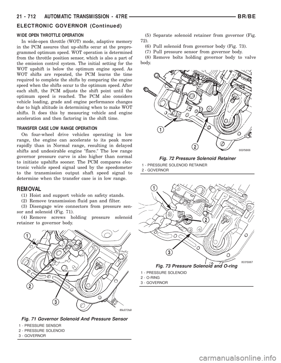
REMOVAL
(1) Hoist and support vehicle on safety stands.
(2) Remove transmission fluid pan and filter.
(3) Disengage wire connectors from pressure sen-
sor and solenoid (Fig. 71).
(4) Remove screws holding pressure solenoid
retainer to governor body.(5) Separate solenoid retainer from governor (Fig.
72).
(6) Pull solenoid from governor body (Fig. 73).
(7) Pull pressure sensor from governor body.
(8) Remove bolts holding governor body to valve
body.
Fig. 71 Governor Solenoid And Pressure Sensor
1 - PRESSURE SENSOR
2 - PRESSURE SOLENOID
3 - GOVERNOR
Fig. 72 Pressure Solenoid Retainer
1 - PRESSURE SOLENOID RETAINER
2 - GOVERNOR
Fig. 73 Pressure Solenoid and O-ring
1 - PRESSURE SOLENOID
2 - O-RING
3 - GOVERNOR
21 - 712 AUTOMATIC TRANSMISSION - 47REBR/BE
ELECTRONIC GOVERNOR (Continued)
Page 2348 of 2889
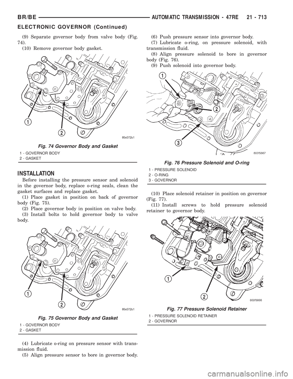
(9) Separate governor body from valve body (Fig.
74).
(10) Remove governor body gasket.
INSTALLATION
Before installing the pressure sensor and solenoid
in the governor body, replace o-ring seals, clean the
gasket surfaces and replace gasket.
(1) Place gasket in position on back of governor
body (Fig. 75).
(2) Place governor body in position on valve body.
(3) Install bolts to hold governor body to valve
body.
(4) Lubricate o-ring on pressure sensor with trans-
mission fluid.
(5) Align pressure sensor to bore in governor body.(6) Push pressure sensor into governor body.
(7) Lubricate o-ring, on pressure solenoid, with
transmission fluid.
(8) Align pressure solenoid to bore in governor
body (Fig. 76).
(9) Push solenoid into governor body.
(10) Place solenoid retainer in position on governor
(Fig. 77).
(11) Install screws to hold pressure solenoid
retainer to governor body.
Fig. 74 Governor Body and Gasket
1 - GOVERNOR BODY
2 - GASKET
Fig. 75 Governor Body and Gasket
1 - GOVERNOR BODY
2 - GASKET
Fig. 76 Pressure Solenoid and O-ring
1 - PRESSURE SOLENOID
2 - O-RING
3 - GOVERNOR
Fig. 77 Pressure Solenoid Retainer
1 - PRESSURE SOLENOID RETAINER
2 - GOVERNOR
BR/BEAUTOMATIC TRANSMISSION - 47RE 21 - 713
ELECTRONIC GOVERNOR (Continued)
Page 2349 of 2889
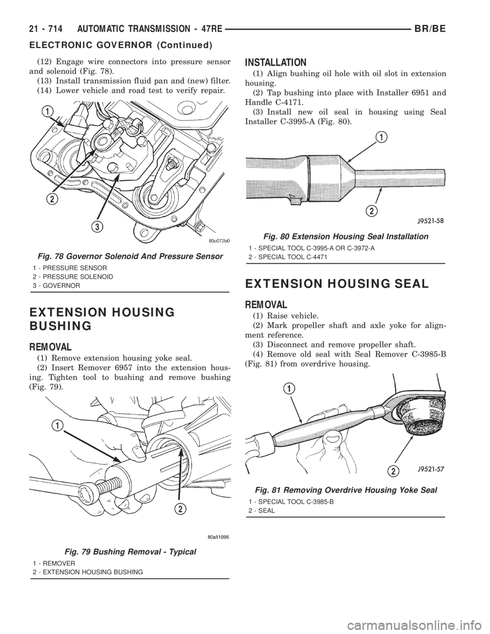
(12) Engage wire connectors into pressure sensor
and solenoid (Fig. 78).
(13) Install transmission fluid pan and (new) filter.
(14) Lower vehicle and road test to verify repair.
EXTENSION HOUSING
BUSHING
REMOVAL
(1) Remove extension housing yoke seal.
(2) Insert Remover 6957 into the extension hous-
ing. Tighten tool to bushing and remove bushing
(Fig. 79).
INSTALLATION
(1) Align bushing oil hole with oil slot in extension
housing.
(2) Tap bushing into place with Installer 6951 and
Handle C-4171.
(3) Install new oil seal in housing using Seal
Installer C-3995-A (Fig. 80).
EXTENSION HOUSING SEAL
REMOVAL
(1) Raise vehicle.
(2) Mark propeller shaft and axle yoke for align-
ment reference.
(3) Disconnect and remove propeller shaft.
(4) Remove old seal with Seal Remover C-3985-B
(Fig. 81) from overdrive housing.
Fig. 78 Governor Solenoid And Pressure Sensor
1 - PRESSURE SENSOR
2 - PRESSURE SOLENOID
3 - GOVERNOR
Fig. 79 Bushing Removal - Typical
1 - REMOVER
2 - EXTENSION HOUSING BUSHING
Fig. 80 Extension Housing Seal Installation
1 - SPECIAL TOOL C-3995-A OR C-3972-A
2 - SPECIAL TOOL C-4471
Fig. 81 Removing Overdrive Housing Yoke Seal
1 - SPECIAL TOOL C-3985-B
2 - SEAL
21 - 714 AUTOMATIC TRANSMISSION - 47REBR/BE
ELECTRONIC GOVERNOR (Continued)
Page 2350 of 2889
INSTALLATION
(1) Place seal in position on overdrive housing.
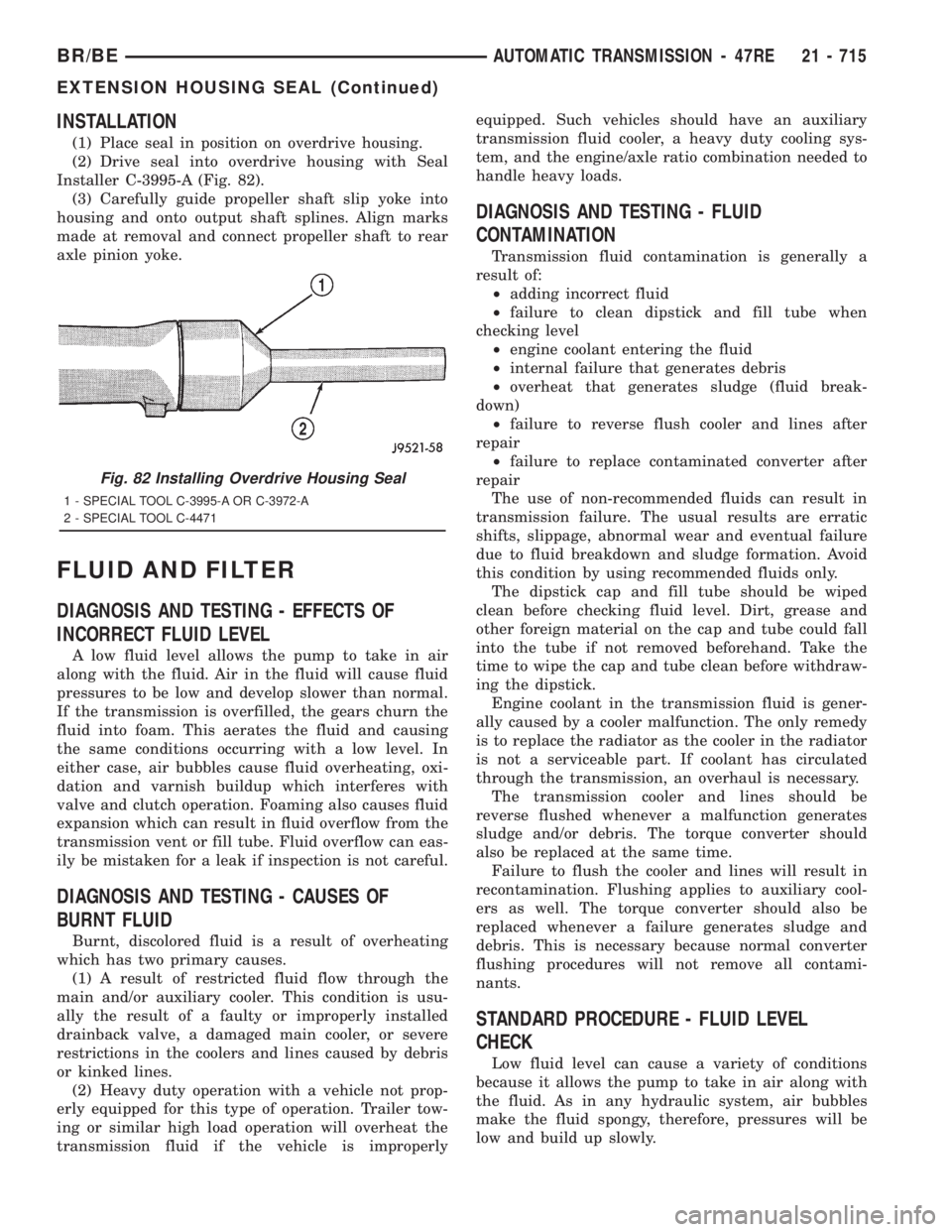
(2) Drive seal into overdrive housing with Seal
Installer C-3995-A (Fig. 82).
(3) Carefully guide propeller shaft slip yoke into
housing and onto output shaft splines. Align marks
made at removal and connect propeller shaft to rear
axle pinion yoke.
FLUID AND FILTER
DIAGNOSIS AND TESTING - EFFECTS OF
INCORRECT FLUID LEVEL
A low fluid level allows the pump to take in air
along with the fluid. Air in the fluid will cause fluid
pressures to be low and develop slower than normal.
If the transmission is overfilled, the gears churn the
fluid into foam. This aerates the fluid and causing
the same conditions occurring with a low level. In
either case, air bubbles cause fluid overheating, oxi-
dation and varnish buildup which interferes with
valve and clutch operation. Foaming also causes fluid
expansion which can result in fluid overflow from the
transmission vent or fill tube. Fluid overflow can eas-
ily be mistaken for a leak if inspection is not careful.
DIAGNOSIS AND TESTING - CAUSES OF
BURNT FLUID
Burnt, discolored fluid is a result of overheating
which has two primary causes.
(1) A result of restricted fluid flow through the
main and/or auxiliary cooler. This condition is usu-
ally the result of a faulty or improperly installed
drainback valve, a damaged main cooler, or severe
restrictions in the coolers and lines caused by debris
or kinked lines.
(2) Heavy duty operation with a vehicle not prop-
erly equipped for this type of operation. Trailer tow-
ing or similar high load operation will overheat the
transmission fluid if the vehicle is improperlyequipped. Such vehicles should have an auxiliary
transmission fluid cooler, a heavy duty cooling sys-
tem, and the engine/axle ratio combination needed to
handle heavy loads.
DIAGNOSIS AND TESTING - FLUID
CONTAMINATION
Transmission fluid contamination is generally a
result of:
²adding incorrect fluid
²failure to clean dipstick and fill tube when
checking level
²engine coolant entering the fluid
²internal failure that generates debris
²overheat that generates sludge (fluid break-
down)
²failure to reverse flush cooler and lines after
repair
²failure to replace contaminated converter after
repair
The use of non-recommended fluids can result in
transmission failure. The usual results are erratic
shifts, slippage, abnormal wear and eventual failure
due to fluid breakdown and sludge formation. Avoid
this condition by using recommended fluids only.
The dipstick cap and fill tube should be wiped
clean before checking fluid level. Dirt, grease and
other foreign material on the cap and tube could fall
into the tube if not removed beforehand. Take the
time to wipe the cap and tube clean before withdraw-
ing the dipstick.
Engine coolant in the transmission fluid is gener-
ally caused by a cooler malfunction. The only remedy
is to replace the radiator as the cooler in the radiator
is not a serviceable part. If coolant has circulated
through the transmission, an overhaul is necessary.
The transmission cooler and lines should be
reverse flushed whenever a malfunction generates
sludge and/or debris. The torque converter should
also be replaced at the same time.
Failure to flush the cooler and lines will result in
recontamination. Flushing applies to auxiliary cool-
ers as well. The torque converter should also be
replaced whenever a failure generates sludge and
debris. This is necessary because normal converter
flushing procedures will not remove all contami-
nants.
STANDARD PROCEDURE - FLUID LEVEL
CHECK
Low fluid level can cause a variety of conditions
because it allows the pump to take in air along with
the fluid. As in any hydraulic system, air bubbles
make the fluid spongy, therefore, pressures will be
low and build up slowly.
Fig. 82 Installing Overdrive Housing Seal
1 - SPECIAL TOOL C-3995-A OR C-3972-A
2 - SPECIAL TOOL C-4471
BR/BEAUTOMATIC TRANSMISSION - 47RE 21 - 715
EXTENSION HOUSING SEAL (Continued)