DODGE RAM 2001 Service Repair Manual
Manufacturer: DODGE, Model Year: 2001, Model line: RAM, Model: DODGE RAM 2001Pages: 2889, PDF Size: 68.07 MB
Page 2381 of 2889
WARNING: THE NEXT STEP IN GEARTRAIN
ASSEMBLY INVOLVES COMPRESSING THE DIRECT
CLUTCH HUB AND SPRING. IT IS EXTREMELY
IMPORTANT THAT PROPER EQUIPMENT BE USED
TO COMPRESS THE SPRING AS SPRING FORCE IS
APPROXIMATELY 830 POUNDS. USE COMPRES-
SOR TOOL C-6227-1 AND A HYDRAULIC-TYPE
SHOP PRESS WITH A MINIMUM RAM TRAVEL OF 6
INCHES. THE PRESS MUST ALSO HAVE A BED
THAT CAN BE ADJUSTED UP OR DOWN AS
REQUIRED. RELEASE CLUTCH SPRING TENSION
SLOWLY AND COMPLETELY TO AVOID PERSONAL
INJURY.
(20) Position Compressor Tool 6227-1 on clutch
hub.
(21) Compress clutch hub and spring just enough
to place tension on hub and hold it in place.
(22) Slowly compress clutch hub and spring. Com-
press spring and hub only enough to expose ring
grooves for clutch pack snap-ring and clutch hub
retaining ring.
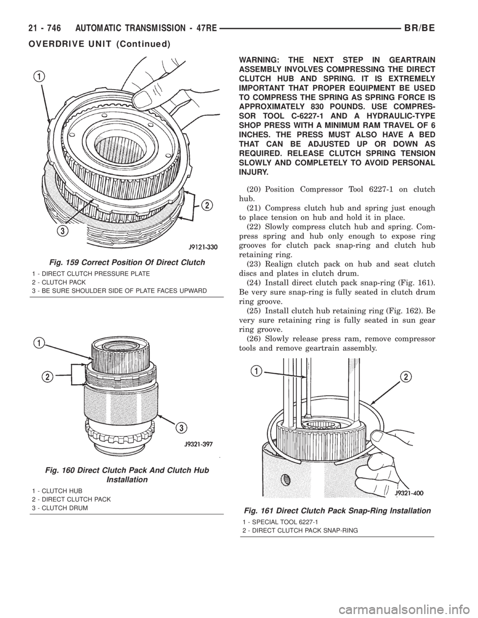
(23) Realign clutch pack on hub and seat clutch
discs and plates in clutch drum.
(24) Install direct clutch pack snap-ring (Fig. 161).
Be very sure snap-ring is fully seated in clutch drum
ring groove.
(25) Install clutch hub retaining ring (Fig. 162). Be
very sure retaining ring is fully seated in sun gear
ring groove.
(26) Slowly release press ram, remove compressor
tools and remove geartrain assembly.
Fig. 159 Correct Position Of Direct Clutch
1 - DIRECT CLUTCH PRESSURE PLATE
2 - CLUTCH PACK
3 - BE SURE SHOULDER SIDE OF PLATE FACES UPWARD
Fig. 160 Direct Clutch Pack And Clutch Hub
Installation
1 - CLUTCH HUB
2 - DIRECT CLUTCH PACK
3 - CLUTCH DRUM
Fig. 161 Direct Clutch Pack Snap-Ring Installation
1 - SPECIAL TOOL 6227-1
2 - DIRECT CLUTCH PACK SNAP-RING
21 - 746 AUTOMATIC TRANSMISSION - 47REBR/BE
OVERDRIVE UNIT (Continued)
Page 2382 of 2889
GEAR CASE
(1) Position park pawl and spring in case and
install park pawl shaft. Verify that end of spring
with 90É bend is hooked to pawl and straight end of
spring is seated against case.
(2) Install pawl shaft retaining bolt. Tighten bolt
to 27 N´m (20 ft. lbs.) torque.
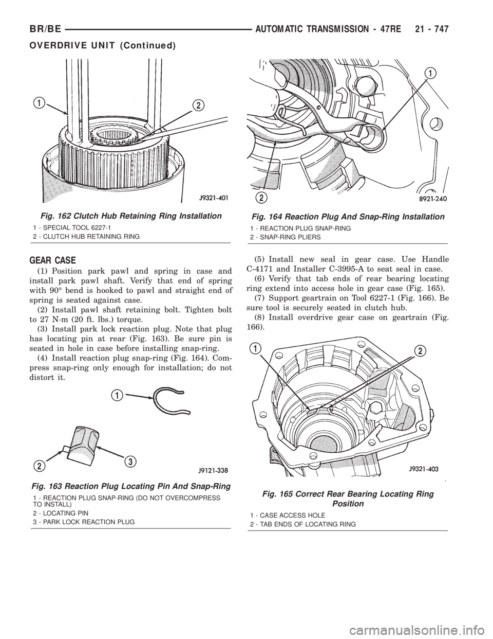
(3) Install park lock reaction plug. Note that plug
has locating pin at rear (Fig. 163). Be sure pin is
seated in hole in case before installing snap-ring.
(4) Install reaction plug snap-ring (Fig. 164). Com-
press snap-ring only enough for installation; do not
distort it.(5) Install new seal in gear case. Use Handle
C-4171 and Installer C-3995-A to seat seal in case.
(6) Verify that tab ends of rear bearing locating
ring extend into access hole in gear case (Fig. 165).
(7) Support geartrain on Tool 6227-1 (Fig. 166). Be
sure tool is securely seated in clutch hub.
(8) Install overdrive gear case on geartrain (Fig.
166).
Fig. 162 Clutch Hub Retaining Ring Installation
1 - SPECIAL TOOL 6227-1
2 - CLUTCH HUB RETAINING RING
Fig. 163 Reaction Plug Locating Pin And Snap-Ring
1 - REACTION PLUG SNAP-RING (DO NOT OVERCOMPRESS
TO INSTALL)
2 - LOCATING PIN
3 - PARK LOCK REACTION PLUG
Fig. 164 Reaction Plug And Snap-Ring Installation
1 - REACTION PLUG SNAP-RING
2 - SNAP-RING PLIERS
Fig. 165 Correct Rear Bearing Locating Ring
Position
1 - CASE ACCESS HOLE
2 - TAB ENDS OF LOCATING RING
BR/BEAUTOMATIC TRANSMISSION - 47RE 21 - 747
OVERDRIVE UNIT (Continued)
Page 2383 of 2889
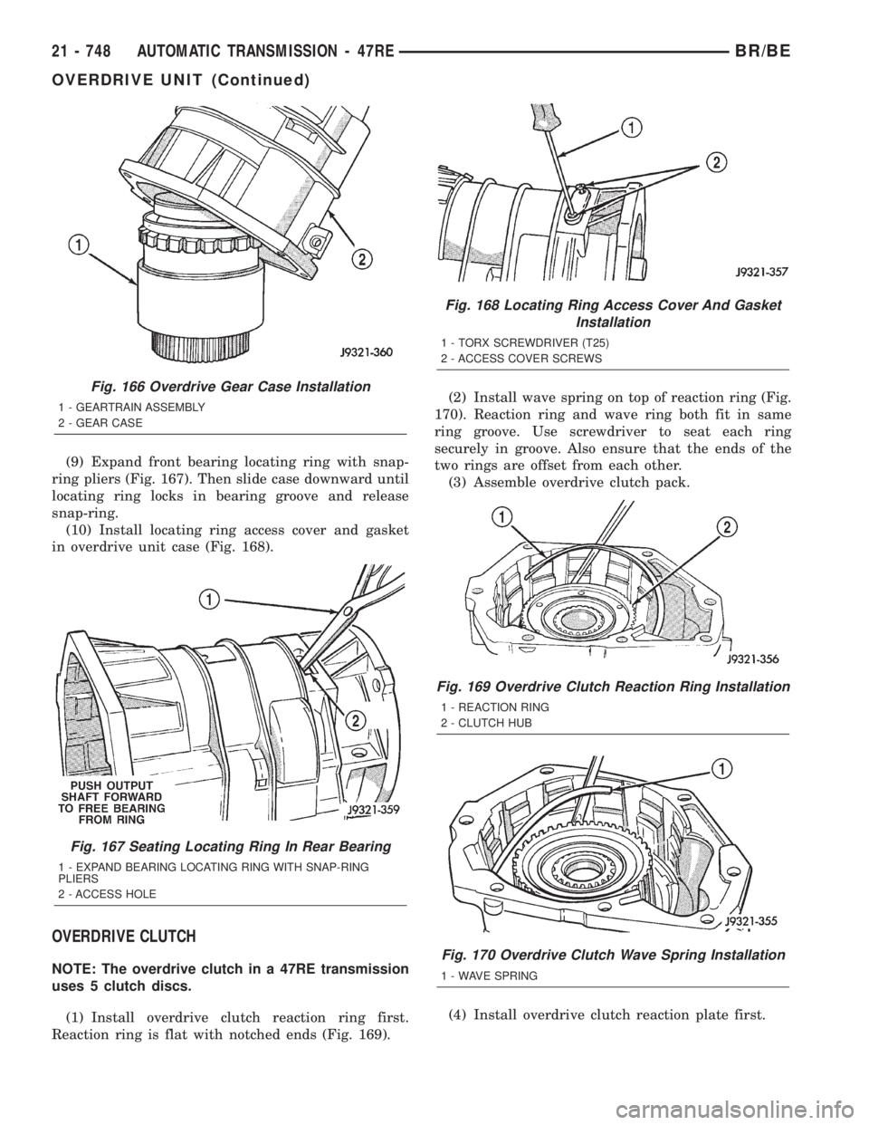
(9) Expand front bearing locating ring with snap-
ring pliers (Fig. 167). Then slide case downward until
locating ring locks in bearing groove and release
snap-ring.
(10) Install locating ring access cover and gasket
in overdrive unit case (Fig. 168).
OVERDRIVE CLUTCH
NOTE: The overdrive clutch in a 47RE transmission
uses 5 clutch discs.
(1) Install overdrive clutch reaction ring first.
Reaction ring is flat with notched ends (Fig. 169).(2) Install wave spring on top of reaction ring (Fig.
170). Reaction ring and wave ring both fit in same
ring groove. Use screwdriver to seat each ring
securely in groove. Also ensure that the ends of the
two rings are offset from each other.
(3) Assemble overdrive clutch pack.
(4) Install overdrive clutch reaction plate first.
Fig. 166 Overdrive Gear Case Installation
1 - GEARTRAIN ASSEMBLY
2 - GEAR CASE
Fig. 167 Seating Locating Ring In Rear Bearing
1 - EXPAND BEARING LOCATING RING WITH SNAP-RING
PLIERS
2 - ACCESS HOLE
Fig. 168 Locating Ring Access Cover And Gasket
Installation
1 - TORX SCREWDRIVER (T25)
2 - ACCESS COVER SCREWS
Fig. 169 Overdrive Clutch Reaction Ring Installation
1 - REACTION RING
2 - CLUTCH HUB
Fig. 170 Overdrive Clutch Wave Spring Installation
1 - WAVE SPRING
21 - 748 AUTOMATIC TRANSMISSION - 47REBR/BE
OVERDRIVE UNIT (Continued)
Page 2384 of 2889
NOTE: The reaction plate is thicker than the pres-
sure plate in a 47RE transmission.
(5) Install first clutch disc followed by first clutch
plate. Then install remaining clutch discs and plates
in same order.
(6) Install clutch pack pressure plate.
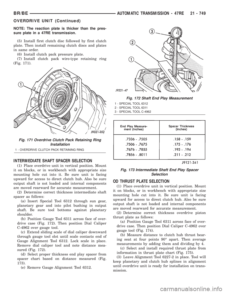
(7) Install clutch pack wire-type retaining ring
(Fig. 171).
INTERMEDIATE SHAFT SPACER SELECTION
(1) Place overdrive unit in vertical position. Mount
it on blocks, or in workbench with appropriate size
mounting hole cut into it. Be sure unit is facing
upward for access to direct clutch hub. Also be sure
output shaft is not loaded and internal components
are moved rearward for accurate measurement.
(2) Determine correct thickness intermediate shaft
spacer as follows:
(a) Insert Special Tool 6312 through sun gear,
planetary gear and into pilot bushing in output
shaft. Be sure tool bottoms against planetary
shoulder.
(b) Position Gauge Tool 6311 across face of over-
drive case (Fig. 172). Then position Dial Caliper
C-4962 over gauge tool.
(c) Extend sliding scale of dial caliper downward
through gauge tool slot until scale contacts end of
Gauge Alignment Tool 6312. Lock scale in place.
Remove dial caliper tool and note distance mea-
sured (Fig. 172).
(d) Select proper thickness end play spacer from
spacer chart based on distance measured (Fig.
173).
(e) Remove Gauge Alignment Tool 6312.
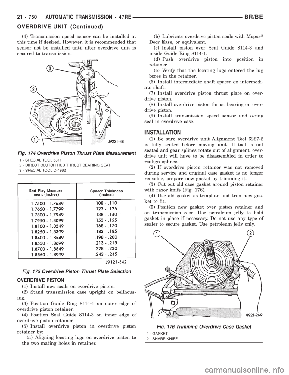
OD THRUST PLATE SELECTION
(1) Place overdrive unit in vertical position. Mount
it on blocks, or in workbench with appropriate size
mounting hole cut into it. Be sure unit is facing
upward for access to direct clutch hub. Also be sure
output shaft is not loaded and internal components
are moved rearward for accurate measurement.
(2) Determine correct thickness overdrive piston
thrust plate as follows:
(a) Position Gauge Tool 6311 across face of over-
drive case. Then position Dial Caliper C-4962 over
gauge tool (Fig. 174).
(b) Measure distance to clutch hub thrust bear-
ing seat at four points 90É apart. Then average
measurements by adding them and dividing by 4.
(c) Select and install required thrust plate from
information in thrust plate chart (Fig. 175).
(3) Leave Alignment Tool 6227-2 in place. Tool will
keep planetary and clutch hub splines in alignment
until overdrive unit is ready for installation on trans-
mission.
Fig. 171 Overdrive Clutch Pack Retaining Ring
Installation
1 - OVERDRIVE CLUTCH PACK RETAINING RING
Fig. 172 Shaft End Play Measurement
1 - SPECIAL TOOL 6312
2 - SPECIAL TOOL 6311
3 - SPECIAL TOOL C-4962
Fig. 173 Intermediate Shaft End Play Spacer
Selection
BR/BEAUTOMATIC TRANSMISSION - 47RE 21 - 749
OVERDRIVE UNIT (Continued)
Page 2385 of 2889
(4) Transmission speed sensor can be installed at
this time if desired. However, it is recommended that
sensor not be installed until after overdrive unit is
secured to transmission.
OVERDRIVE PISTON
(1) Install new seals on overdrive piston.
(2) Stand transmission case upright on bellhous-
ing.
(3) Position Guide Ring 8114-1 on outer edge of
overdrive piston retainer.
(4) Position Seal Guide 8114-3 on inner edge of
overdrive piston retainer.
(5) Install overdrive piston in overdrive piston
retainer by:
(a) Aligning locating lugs on overdrive piston to
the two mating holes in retainer.(b) Lubricate overdrive piston seals with Mopart
Door Ease, or equivalent.
(c) Install piston over Seal Guide 8114-3 and
inside Guide Ring 8114-1.
(d) Push overdrive piston into position in
retainer.
(e) Verify that the locating lugs entered the lug
bores in the retainer.
(6) Install intermediate shaft spacer on intermedi-
ate shaft.
(7) Install overdrive piston thrust plate on over-
drive piston.
(8) Install overdrive piston thrust bearing on over-
drive piston.
(9) Install transmission speed sensor and o-ring
seal in overdrive case.
INSTALLATION
(1) Be sure overdrive unit Alignment Tool 6227-2
is fully seated before moving unit. If tool is not
seated and gear splines rotate out of alignment, over-
drive unit will have to be disassembled in order to
realign splines.
(2) If overdrive piston retainer was not removed
during service and original case gasket is no longer
reusable, prepare new gasket by trimming it.
(3) Cut out old case gasket around piston retainer
with razor knife (Fig. 176).
(4) Use old gasket as template and trim new gas-
ket to fit.
(5) Position new gasket over piston retainer and
on transmission case. Use petroleum jelly to hold
gasket in place if necessary. Do not use any type of
sealer to secure gasket. Use petroleum jelly only.
Fig. 174 Overdrive Piston Thrust Plate Measurement
1 - SPECIAL TOOL 6311
2 - DIRECT CLUTCH HUB THRUST BEARING SEAT
3 - SPECIAL TOOL C-4962
Fig. 175 Overdrive Piston Thrust Plate Selection
Fig. 176 Trimming Overdrive Case Gasket
1 - GASKET
2 - SHARP KNIFE
21 - 750 AUTOMATIC TRANSMISSION - 47REBR/BE
OVERDRIVE UNIT (Continued)
Page 2386 of 2889
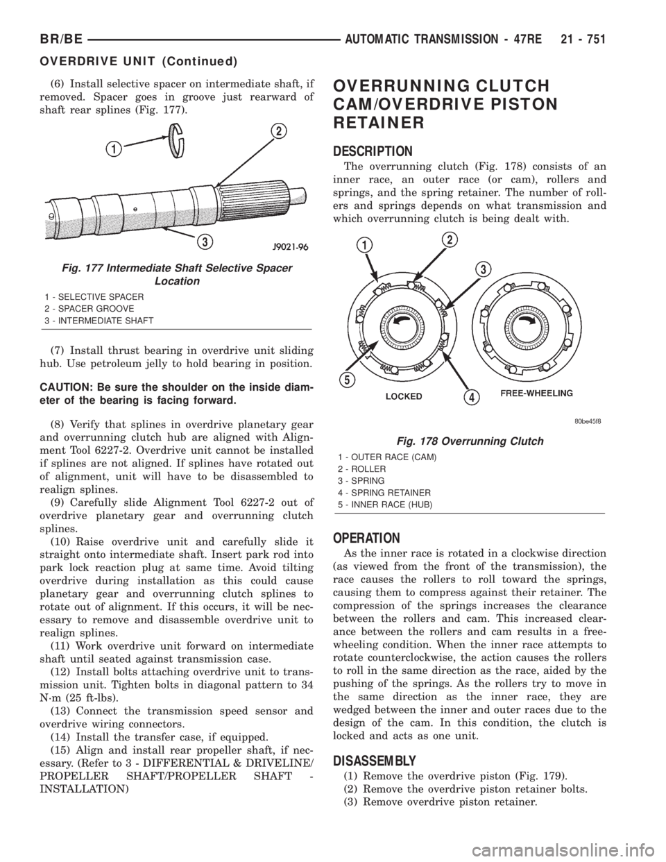
(6) Install selective spacer on intermediate shaft, if
removed. Spacer goes in groove just rearward of
shaft rear splines (Fig. 177).
(7) Install thrust bearing in overdrive unit sliding
hub. Use petroleum jelly to hold bearing in position.
CAUTION: Be sure the shoulder on the inside diam-
eter of the bearing is facing forward.
(8) Verify that splines in overdrive planetary gear
and overrunning clutch hub are aligned with Align-
ment Tool 6227-2. Overdrive unit cannot be installed
if splines are not aligned. If splines have rotated out
of alignment, unit will have to be disassembled to
realign splines.
(9) Carefully slide Alignment Tool 6227-2 out of
overdrive planetary gear and overrunning clutch
splines.
(10) Raise overdrive unit and carefully slide it
straight onto intermediate shaft. Insert park rod into
park lock reaction plug at same time. Avoid tilting
overdrive during installation as this could cause
planetary gear and overrunning clutch splines to
rotate out of alignment. If this occurs, it will be nec-
essary to remove and disassemble overdrive unit to
realign splines.
(11) Work overdrive unit forward on intermediate
shaft until seated against transmission case.
(12) Install bolts attaching overdrive unit to trans-
mission unit. Tighten bolts in diagonal pattern to 34
N´m (25 ft-lbs).
(13) Connect the transmission speed sensor and
overdrive wiring connectors.
(14) Install the transfer case, if equipped.
(15) Align and install rear propeller shaft, if nec-
essary. (Refer to 3 - DIFFERENTIAL & DRIVELINE/
PROPELLER SHAFT/PROPELLER SHAFT -
INSTALLATION)OVERRUNNING CLUTCH
CAM/OVERDRIVE PISTON
RETAINER
DESCRIPTION
The overrunning clutch (Fig. 178) consists of an
inner race, an outer race (or cam), rollers and
springs, and the spring retainer. The number of roll-
ers and springs depends on what transmission and
which overrunning clutch is being dealt with.
OPERATION
As the inner race is rotated in a clockwise direction
(as viewed from the front of the transmission), the
race causes the rollers to roll toward the springs,
causing them to compress against their retainer. The
compression of the springs increases the clearance
between the rollers and cam. This increased clear-
ance between the rollers and cam results in a free-
wheeling condition. When the inner race attempts to
rotate counterclockwise, the action causes the rollers
to roll in the same direction as the race, aided by the
pushing of the springs. As the rollers try to move in
the same direction as the inner race, they are
wedged between the inner and outer races due to the
design of the cam. In this condition, the clutch is
locked and acts as one unit.
DISASSEMBLY
(1) Remove the overdrive piston (Fig. 179).
(2) Remove the overdrive piston retainer bolts.
(3) Remove overdrive piston retainer.
Fig. 177 Intermediate Shaft Selective Spacer
Location
1 - SELECTIVE SPACER
2 - SPACER GROOVE
3 - INTERMEDIATE SHAFT
Fig. 178 Overrunning Clutch
1 - OUTER RACE (CAM)
2 - ROLLER
3 - SPRING
4 - SPRING RETAINER
5 - INNER RACE (HUB)
BR/BEAUTOMATIC TRANSMISSION - 47RE 21 - 751
OVERDRIVE UNIT (Continued)
Page 2387 of 2889
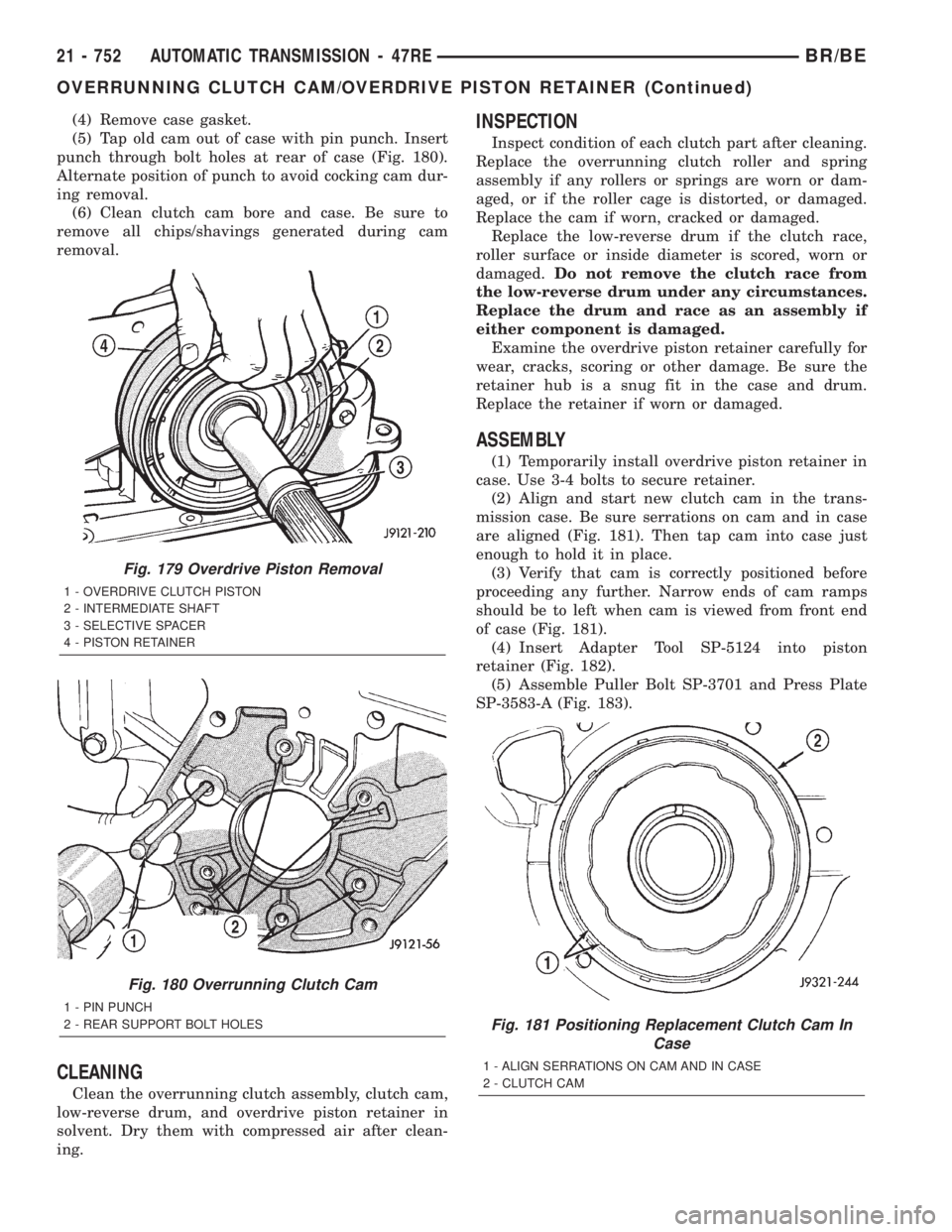
(4) Remove case gasket.
(5) Tap old cam out of case with pin punch. Insert
punch through bolt holes at rear of case (Fig. 180).
Alternate position of punch to avoid cocking cam dur-
ing removal.
(6) Clean clutch cam bore and case. Be sure to
remove all chips/shavings generated during cam
removal.
CLEANING
Clean the overrunning clutch assembly, clutch cam,
low-reverse drum, and overdrive piston retainer in
solvent. Dry them with compressed air after clean-
ing.
INSPECTION
Inspect condition of each clutch part after cleaning.
Replace the overrunning clutch roller and spring
assembly if any rollers or springs are worn or dam-
aged, or if the roller cage is distorted, or damaged.
Replace the cam if worn, cracked or damaged.
Replace the low-reverse drum if the clutch race,
roller surface or inside diameter is scored, worn or
damaged.Do not remove the clutch race from
the low-reverse drum under any circumstances.
Replace the drum and race as an assembly if
either component is damaged.
Examine the overdrive piston retainer carefully for
wear, cracks, scoring or other damage. Be sure the
retainer hub is a snug fit in the case and drum.
Replace the retainer if worn or damaged.
ASSEMBLY
(1) Temporarily install overdrive piston retainer in
case. Use 3-4 bolts to secure retainer.
(2) Align and start new clutch cam in the trans-
mission case. Be sure serrations on cam and in case
are aligned (Fig. 181). Then tap cam into case just
enough to hold it in place.
(3) Verify that cam is correctly positioned before
proceeding any further. Narrow ends of cam ramps
should be to left when cam is viewed from front end
of case (Fig. 181).
(4) Insert Adapter Tool SP-5124 into piston
retainer (Fig. 182).
(5) Assemble Puller Bolt SP-3701 and Press Plate
SP-3583-A (Fig. 183).
Fig. 179 Overdrive Piston Removal
1 - OVERDRIVE CLUTCH PISTON
2 - INTERMEDIATE SHAFT
3 - SELECTIVE SPACER
4 - PISTON RETAINER
Fig. 180 Overrunning Clutch Cam
1 - PIN PUNCH
2 - REAR SUPPORT BOLT HOLES
Fig. 181 Positioning Replacement Clutch Cam In
Case
1 - ALIGN SERRATIONS ON CAM AND IN CASE
2 - CLUTCH CAM
21 - 752 AUTOMATIC TRANSMISSION - 47REBR/BE
OVERRUNNING CLUTCH CAM/OVERDRIVE PISTON RETAINER (Continued)
Page 2388 of 2889
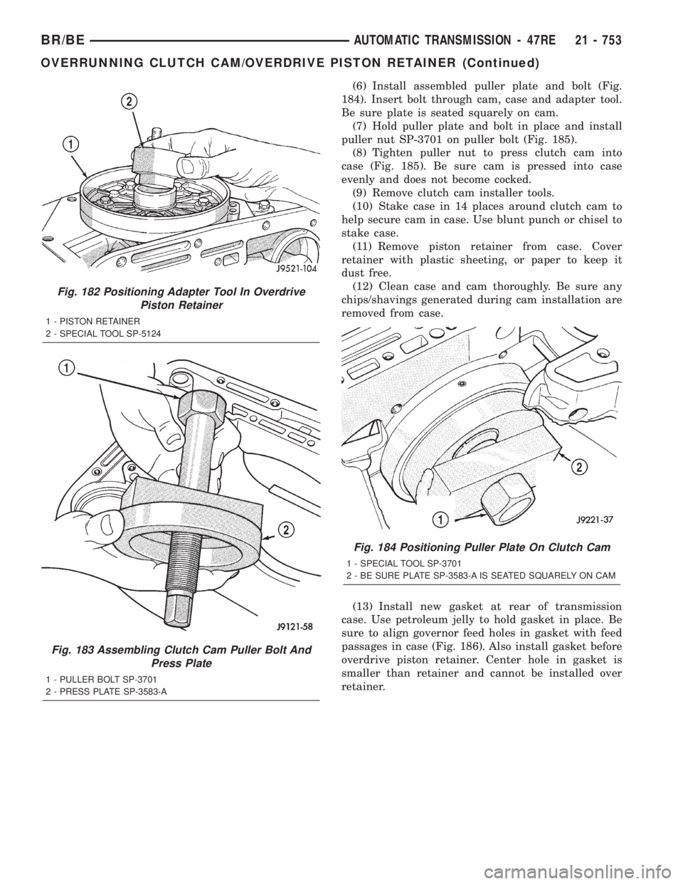
(6) Install assembled puller plate and bolt (Fig.
184). Insert bolt through cam, case and adapter tool.
Be sure plate is seated squarely on cam.
(7) Hold puller plate and bolt in place and install
puller nut SP-3701 on puller bolt (Fig. 185).
(8) Tighten puller nut to press clutch cam into
case (Fig. 185). Be sure cam is pressed into case
evenly and does not become cocked.
(9) Remove clutch cam installer tools.
(10) Stake case in 14 places around clutch cam to
help secure cam in case. Use blunt punch or chisel to
stake case.
(11) Remove piston retainer from case. Cover
retainer with plastic sheeting, or paper to keep it
dust free.
(12) Clean case and cam thoroughly. Be sure any
chips/shavings generated during cam installation are
removed from case.
(13) Install new gasket at rear of transmission
case. Use petroleum jelly to hold gasket in place. Be
sure to align governor feed holes in gasket with feed
passages in case (Fig. 186). Also install gasket before
overdrive piston retainer. Center hole in gasket is
smaller than retainer and cannot be installed over
retainer.
Fig. 182 Positioning Adapter Tool In Overdrive
Piston Retainer
1 - PISTON RETAINER
2 - SPECIAL TOOL SP-5124
Fig. 183 Assembling Clutch Cam Puller Bolt And
Press Plate
1 - PULLER BOLT SP-3701
2 - PRESS PLATE SP-3583-A
Fig. 184 Positioning Puller Plate On Clutch Cam
1 - SPECIAL TOOL SP-3701
2 - BE SURE PLATE SP-3583-A IS SEATED SQUARELY ON CAM
BR/BEAUTOMATIC TRANSMISSION - 47RE 21 - 753
OVERRUNNING CLUTCH CAM/OVERDRIVE PISTON RETAINER (Continued)
Page 2389 of 2889
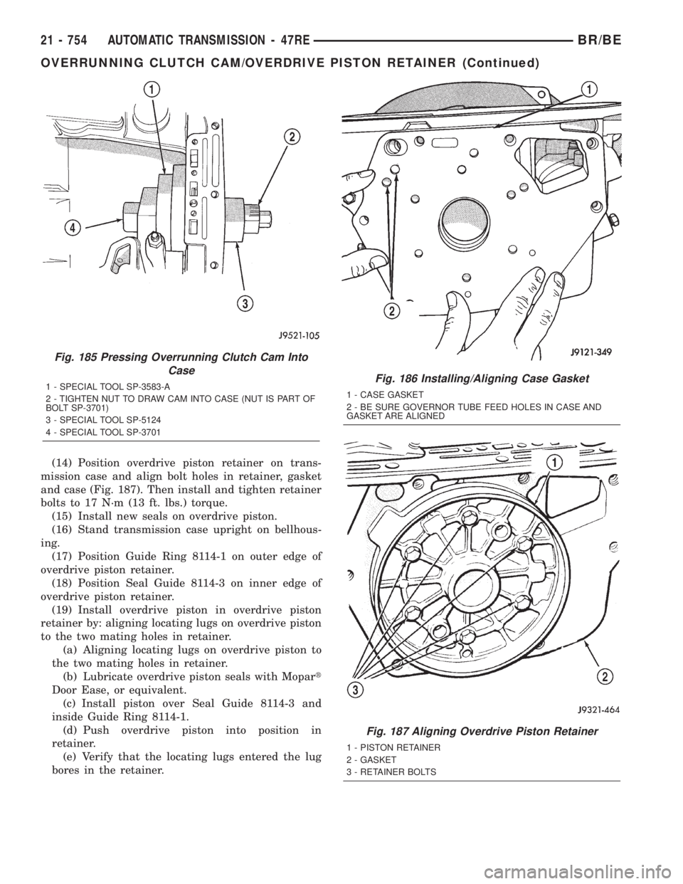
(14) Position overdrive piston retainer on trans-
mission case and align bolt holes in retainer, gasket
and case (Fig. 187). Then install and tighten retainer
bolts to 17 N´m (13 ft. lbs.) torque.
(15) Install new seals on overdrive piston.
(16) Stand transmission case upright on bellhous-
ing.
(17) Position Guide Ring 8114-1 on outer edge of
overdrive piston retainer.
(18) Position Seal Guide 8114-3 on inner edge of
overdrive piston retainer.
(19) Install overdrive piston in overdrive piston
retainer by: aligning locating lugs on overdrive piston
to the two mating holes in retainer.
(a) Aligning locating lugs on overdrive piston to
the two mating holes in retainer.
(b) Lubricate overdrive piston seals with Mopart
Door Ease, or equivalent.
(c) Install piston over Seal Guide 8114-3 and
inside Guide Ring 8114-1.
(d) Push overdrive piston into position in
retainer.
(e) Verify that the locating lugs entered the lug
bores in the retainer.
Fig. 185 Pressing Overrunning Clutch Cam Into
Case
1 - SPECIAL TOOL SP-3583-A
2 - TIGHTEN NUT TO DRAW CAM INTO CASE (NUT IS PART OF
BOLT SP-3701)
3 - SPECIAL TOOL SP-5124
4 - SPECIAL TOOL SP-3701Fig. 186 Installing/Aligning Case Gasket
1 - CASE GASKET
2 - BE SURE GOVERNOR TUBE FEED HOLES IN CASE AND
GASKET ARE ALIGNED
Fig. 187 Aligning Overdrive Piston Retainer
1 - PISTON RETAINER
2 - GASKET
3 - RETAINER BOLTS
21 - 754 AUTOMATIC TRANSMISSION - 47REBR/BE
OVERRUNNING CLUTCH CAM/OVERDRIVE PISTON RETAINER (Continued)
Page 2390 of 2889
PARK/NEUTRAL POSITION
SWITCH
DIAGNOSIS AND TESTING - PARK/NEUTRAL
POSITION SWITCH
The center terminal of the park/neutral position
switch is the starter-circuit terminal. It provides the
ground for the starter solenoid circuit through the
selector lever in PARK and NEUTRAL positions only.
The outer terminals on the switch are for the backup
lamp circuit.
SWITCH TEST
To test the switch, remove the wiring connector.
Test for continuity between the center terminal and
the transmission case. Continuity should exist only
when the transmission is in PARK or NEUTRAL.
Shift the transmission into REVERSE and test
continuity at the switch outer terminals. Continuity
should exist only when the transmission is in
REVERSE. Continuity should not exist between the
outer terminals and the case.
Check gearshift linkage adjustment before replac-
ing a switch that tests faulty.
REMOVAL
(1) Raise vehicle and position drain pan under
switch.
(2) Disconnect switch wires.
(3) Remove switch from case.
INSTALLATION
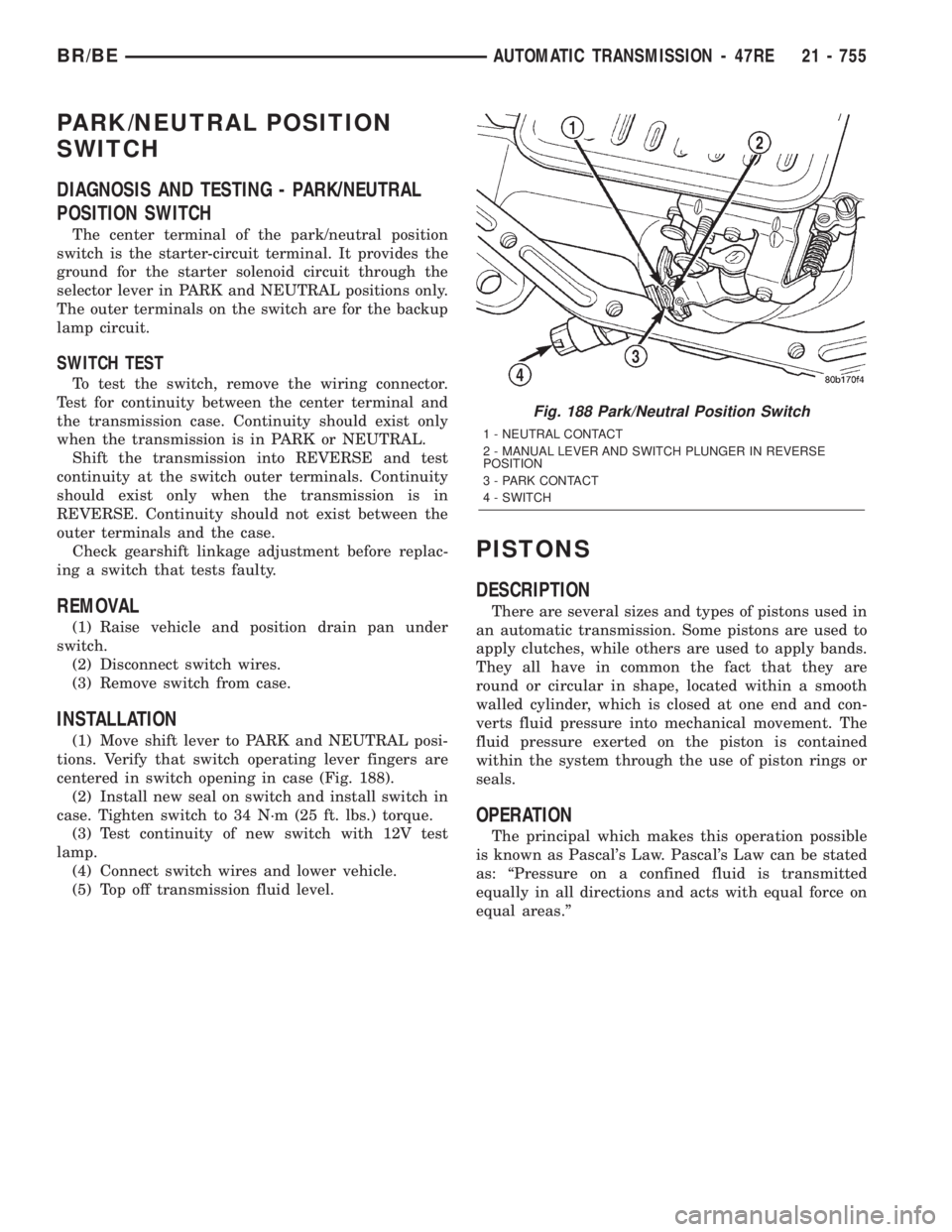
(1) Move shift lever to PARK and NEUTRAL posi-
tions. Verify that switch operating lever fingers are
centered in switch opening in case (Fig. 188).
(2) Install new seal on switch and install switch in
case. Tighten switch to 34 N´m (25 ft. lbs.) torque.
(3) Test continuity of new switch with 12V test
lamp.
(4) Connect switch wires and lower vehicle.
(5) Top off transmission fluid level.
PISTONS
DESCRIPTION
There are several sizes and types of pistons used in
an automatic transmission. Some pistons are used to
apply clutches, while others are used to apply bands.
They all have in common the fact that they are
round or circular in shape, located within a smooth
walled cylinder, which is closed at one end and con-
verts fluid pressure into mechanical movement. The
fluid pressure exerted on the piston is contained
within the system through the use of piston rings or
seals.
OPERATION
The principal which makes this operation possible
is known as Pascal's Law. Pascal's Law can be stated
as: ªPressure on a confined fluid is transmitted
equally in all directions and acts with equal force on
equal areas.º
Fig. 188 Park/Neutral Position Switch
1 - NEUTRAL CONTACT
2 - MANUAL LEVER AND SWITCH PLUNGER IN REVERSE
POSITION
3 - PARK CONTACT
4 - SWITCH
BR/BEAUTOMATIC TRANSMISSION - 47RE 21 - 755