DODGE RAM 2001 Service Repair Manual
Manufacturer: DODGE, Model Year: 2001, Model line: RAM, Model: DODGE RAM 2001Pages: 2889, PDF Size: 68.07 MB
Page 2411 of 2889
STATOR
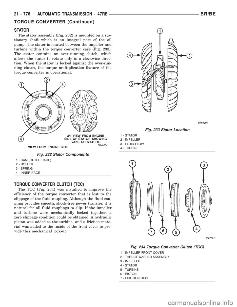
The stator assembly (Fig. 232) is mounted on a sta-
tionary shaft which is an integral part of the oil
pump. The stator is located between the impeller and
turbine within the torque converter case (Fig. 233).
The stator contains an over-running clutch, which
allows the stator to rotate only in a clockwise direc-
tion. When the stator is locked against the over-run-
ning clutch, the torque multiplication feature of the
torque converter is operational.
TORQUE CONVERTER CLUTCH (TCC)
The TCC (Fig. 234) was installed to improve the
efficiency of the torque converter that is lost to the
slippage of the fluid coupling. Although the fluid cou-
pling provides smooth, shock-free power transfer, it is
natural for all fluid couplings to slip. If the impeller
and turbine were mechanically locked together, a
zero slippage condition could be obtained. A hydraulic
piston was added to the turbine, and a friction mate-
rial was added to the inside of the front cover to pro-
vide this mechanical lock-up.
Fig. 232 Stator Components
1 - CAM (OUTER RACE)
2 - ROLLER
3 - SPRING
4 - INNER RACE
Fig. 233 Stator Location
1-STATOR
2 - IMPELLER
3 - FLUID FLOW
4 - TURBINE
Fig. 234 Torque Converter Clutch (TCC)
1 - IMPELLER FRONT COVER
2 - THRUST WASHER ASSEMBLY
3 - IMPELLER
4-STATOR
5 - TURBINE
6 - PISTON
7 - FRICTION DISC
21 - 776 AUTOMATIC TRANSMISSION - 47REBR/BE
TORQUE CONVERTER (Continued)
Page 2412 of 2889
OPERATION
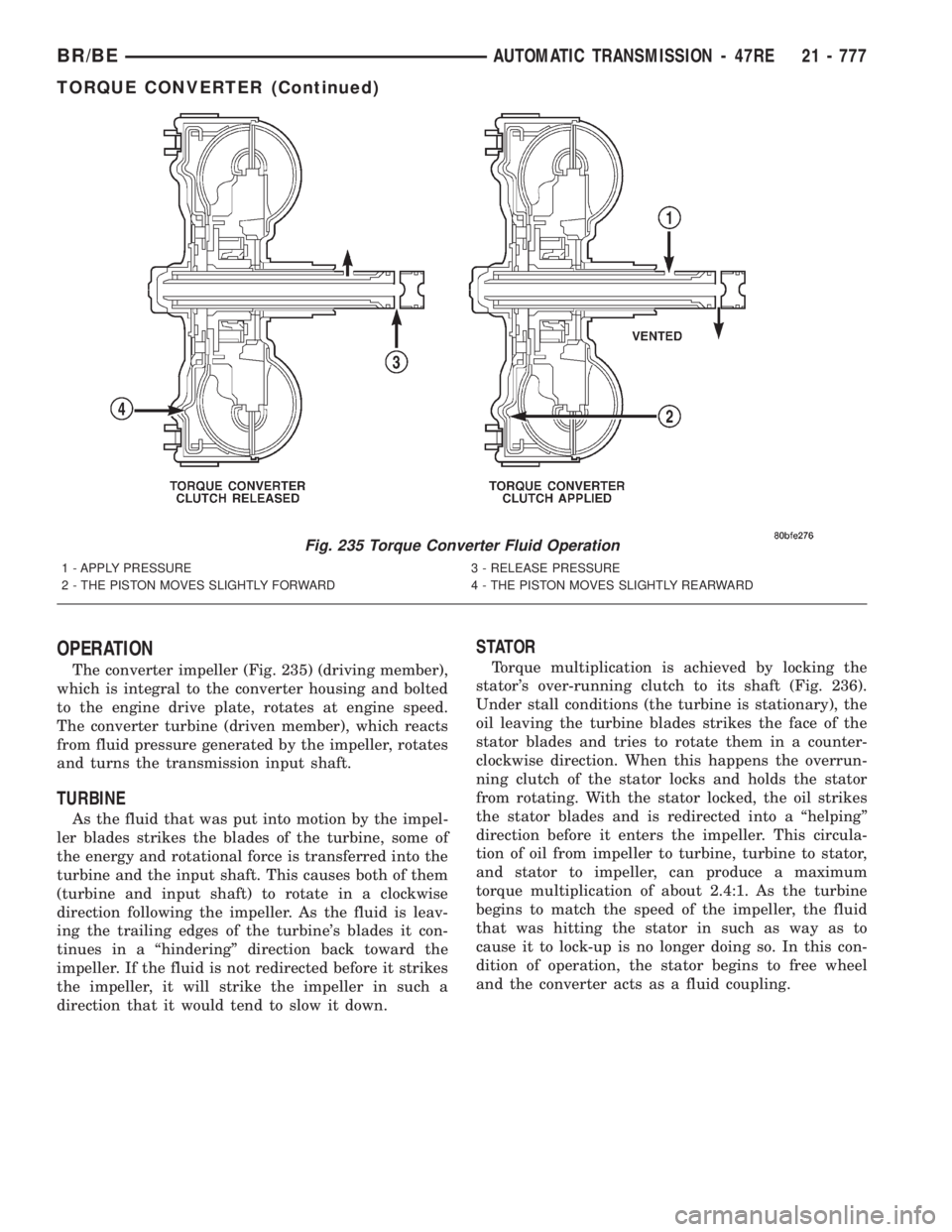
The converter impeller (Fig. 235) (driving member),
which is integral to the converter housing and bolted
to the engine drive plate, rotates at engine speed.
The converter turbine (driven member), which reacts
from fluid pressure generated by the impeller, rotates
and turns the transmission input shaft.
TURBINE
As the fluid that was put into motion by the impel-
ler blades strikes the blades of the turbine, some of
the energy and rotational force is transferred into the
turbine and the input shaft. This causes both of them
(turbine and input shaft) to rotate in a clockwise
direction following the impeller. As the fluid is leav-
ing the trailing edges of the turbine's blades it con-
tinues in a ªhinderingº direction back toward the
impeller. If the fluid is not redirected before it strikes
the impeller, it will strike the impeller in such a
direction that it would tend to slow it down.
STATOR
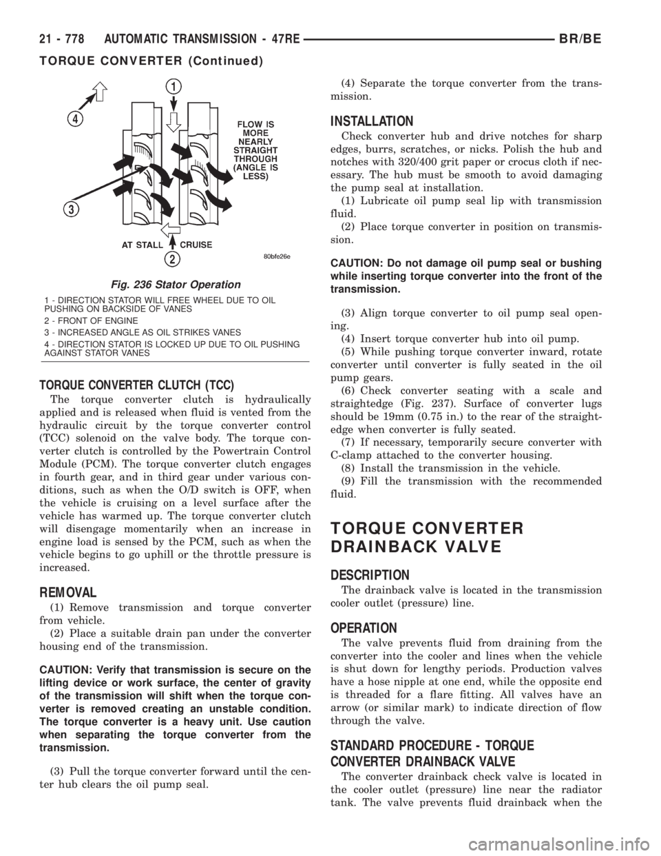
Torque multiplication is achieved by locking the
stator's over-running clutch to its shaft (Fig. 236).
Under stall conditions (the turbine is stationary), the
oil leaving the turbine blades strikes the face of the
stator blades and tries to rotate them in a counter-
clockwise direction. When this happens the overrun-
ning clutch of the stator locks and holds the stator
from rotating. With the stator locked, the oil strikes
the stator blades and is redirected into a ªhelpingº
direction before it enters the impeller. This circula-
tion of oil from impeller to turbine, turbine to stator,
and stator to impeller, can produce a maximum
torque multiplication of about 2.4:1. As the turbine
begins to match the speed of the impeller, the fluid
that was hitting the stator in such as way as to
cause it to lock-up is no longer doing so. In this con-
dition of operation, the stator begins to free wheel
and the converter acts as a fluid coupling.
Fig. 235 Torque Converter Fluid Operation
1 - APPLY PRESSURE 3 - RELEASE PRESSURE
2 - THE PISTON MOVES SLIGHTLY FORWARD 4 - THE PISTON MOVES SLIGHTLY REARWARD
BR/BEAUTOMATIC TRANSMISSION - 47RE 21 - 777
TORQUE CONVERTER (Continued)
Page 2413 of 2889
TORQUE CONVERTER CLUTCH (TCC)
The torque converter clutch is hydraulically
applied and is released when fluid is vented from the
hydraulic circuit by the torque converter control
(TCC) solenoid on the valve body. The torque con-
verter clutch is controlled by the Powertrain Control
Module (PCM). The torque converter clutch engages
in fourth gear, and in third gear under various con-
ditions, such as when the O/D switch is OFF, when
the vehicle is cruising on a level surface after the
vehicle has warmed up. The torque converter clutch
will disengage momentarily when an increase in
engine load is sensed by the PCM, such as when the
vehicle begins to go uphill or the throttle pressure is
increased.
REMOVAL
(1) Remove transmission and torque converter
from vehicle.
(2) Place a suitable drain pan under the converter
housing end of the transmission.
CAUTION: Verify that transmission is secure on the
lifting device or work surface, the center of gravity
of the transmission will shift when the torque con-
verter is removed creating an unstable condition.
The torque converter is a heavy unit. Use caution
when separating the torque converter from the
transmission.
(3) Pull the torque converter forward until the cen-
ter hub clears the oil pump seal.(4) Separate the torque converter from the trans-
mission.
INSTALLATION
Check converter hub and drive notches for sharp
edges, burrs, scratches, or nicks. Polish the hub and
notches with 320/400 grit paper or crocus cloth if nec-
essary. The hub must be smooth to avoid damaging
the pump seal at installation.
(1) Lubricate oil pump seal lip with transmission
fluid.
(2) Place torque converter in position on transmis-
sion.
CAUTION: Do not damage oil pump seal or bushing
while inserting torque converter into the front of the
transmission.
(3) Align torque converter to oil pump seal open-
ing.
(4) Insert torque converter hub into oil pump.
(5) While pushing torque converter inward, rotate
converter until converter is fully seated in the oil
pump gears.
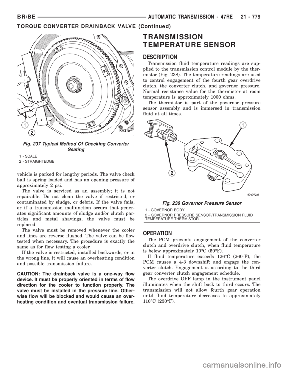
(6) Check converter seating with a scale and
straightedge (Fig. 237). Surface of converter lugs
should be 19mm (0.75 in.) to the rear of the straight-
edge when converter is fully seated.
(7) If necessary, temporarily secure converter with
C-clamp attached to the converter housing.
(8) Install the transmission in the vehicle.
(9) Fill the transmission with the recommended
fluid.
TORQUE CONVERTER
DRAINBACK VALVE
DESCRIPTION
The drainback valve is located in the transmission
cooler outlet (pressure) line.
OPERATION
The valve prevents fluid from draining from the
converter into the cooler and lines when the vehicle
is shut down for lengthy periods. Production valves
have a hose nipple at one end, while the opposite end
is threaded for a flare fitting. All valves have an
arrow (or similar mark) to indicate direction of flow
through the valve.
STANDARD PROCEDURE - TORQUE
CONVERTER DRAINBACK VALVE
The converter drainback check valve is located in
the cooler outlet (pressure) line near the radiator
tank. The valve prevents fluid drainback when the
Fig. 236 Stator Operation
1 - DIRECTION STATOR WILL FREE WHEEL DUE TO OIL
PUSHING ON BACKSIDE OF VANES
2 - FRONT OF ENGINE
3 - INCREASED ANGLE AS OIL STRIKES VANES
4 - DIRECTION STATOR IS LOCKED UP DUE TO OIL PUSHING
AGAINST STATOR VANES
21 - 778 AUTOMATIC TRANSMISSION - 47REBR/BE
TORQUE CONVERTER (Continued)
Page 2414 of 2889
vehicle is parked for lengthy periods. The valve check
ball is spring loaded and has an opening pressure of
approximately 2 psi.
The valve is serviced as an assembly; it is not
repairable. Do not clean the valve if restricted, or
contaminated by sludge, or debris. If the valve fails,
or if a transmission malfunction occurs that gener-
ates significant amounts of sludge and/or clutch par-
ticles and metal shavings, the valve must be
replaced.
The valve must be removed whenever the cooler
and lines are reverse flushed. The valve can be flow
tested when necessary. The procedure is exactly the
same as for flow testing a cooler.
If the valve is restricted, installed backwards, or in
the wrong line, it will cause an overheating condition
and possible transmission failure.
CAUTION: The drainback valve is a one-way flow
device. It must be properly oriented in terms of flow
direction for the cooler to function properly. The
valve must be installed in the pressure line. Other-
wise flow will be blocked and would cause an over-
heating condition and eventual transmission failure.
TRANSMISSION
TEMPERATURE SENSOR
DESCRIPTION
Transmission fluid temperature readings are sup-
plied to the transmission control module by the ther-
mistor (Fig. 238). The temperature readings are used
to control engagement of the fourth gear overdrive
clutch, the converter clutch, and governor pressure.
Normal resistance value for the thermistor at room
temperature is approximately 1000 ohms.
The thermistor is part of the governor pressure
sensor assembly and is immersed in transmission
fluid at all times.
OPERATION
The PCM prevents engagement of the converter
clutch and overdrive clutch, when fluid temperature
is below approximately 10ÉC (50ÉF).
If fluid temperature exceeds 126ÉC (260ÉF), the
PCM causes a 4-3 downshift and engage the con-
verter clutch. Engagement is according to the third
gear converter clutch engagement schedule.
The overdrive OFF lamp in the instrument panel
illuminates when the shift back to third occurs. The
transmission will not allow fourth gear operation
until fluid temperature decreases to approximately
110ÉC (230ÉF).
Fig. 237 Typical Method Of Checking Converter
Seating
1 - SCALE
2 - STRAIGHTEDGE
Fig. 238 Governor Pressure Sensor
1 - GOVERNOR BODY
2 - GOVERNOR PRESSURE SENSOR/TRANSMISSION FLUID
TEMPERATURE THERMISTOR
BR/BEAUTOMATIC TRANSMISSION - 47RE 21 - 779
TORQUE CONVERTER DRAINBACK VALVE (Continued)
Page 2415 of 2889
VALVE BODY
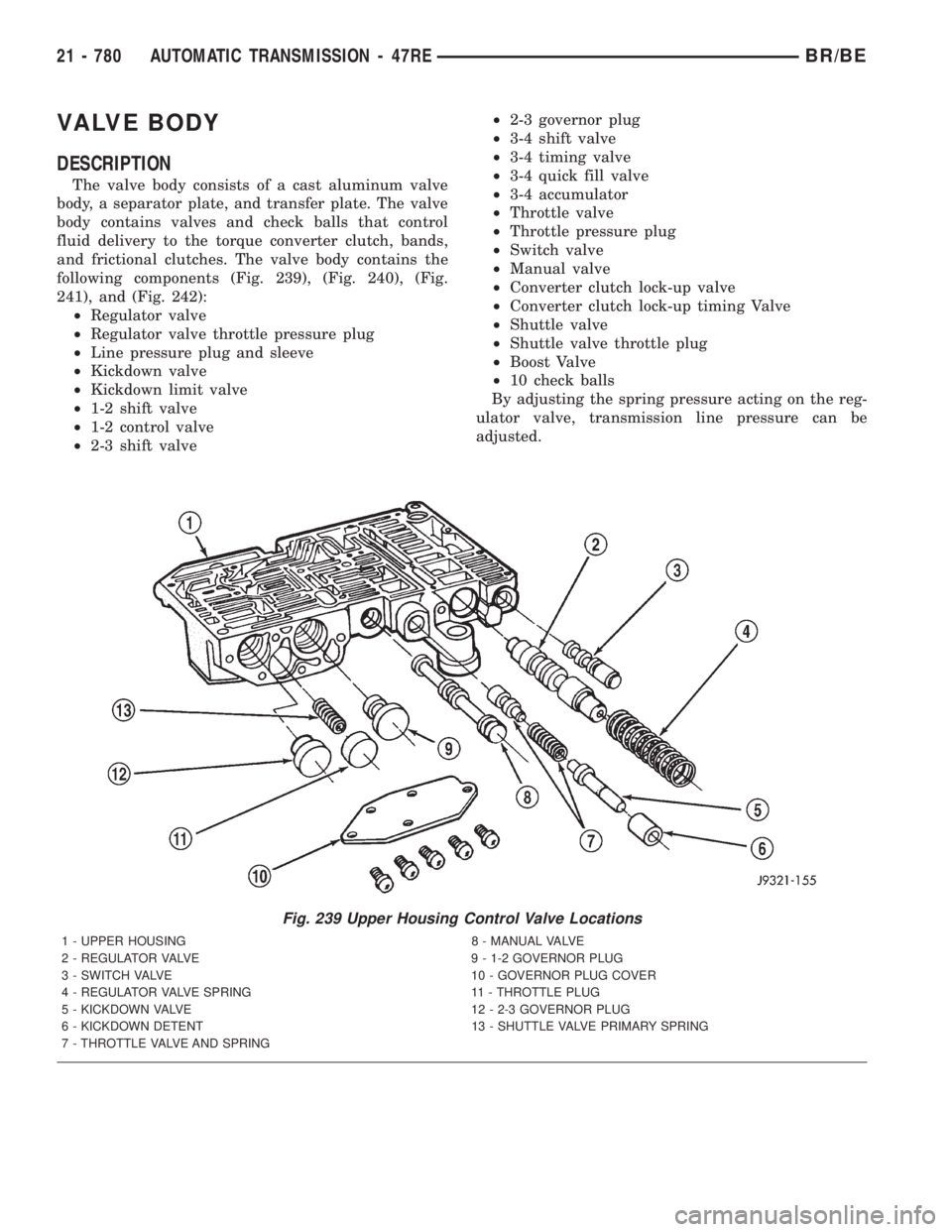
DESCRIPTION
The valve body consists of a cast aluminum valve
body, a separator plate, and transfer plate. The valve
body contains valves and check balls that control
fluid delivery to the torque converter clutch, bands,
and frictional clutches. The valve body contains the
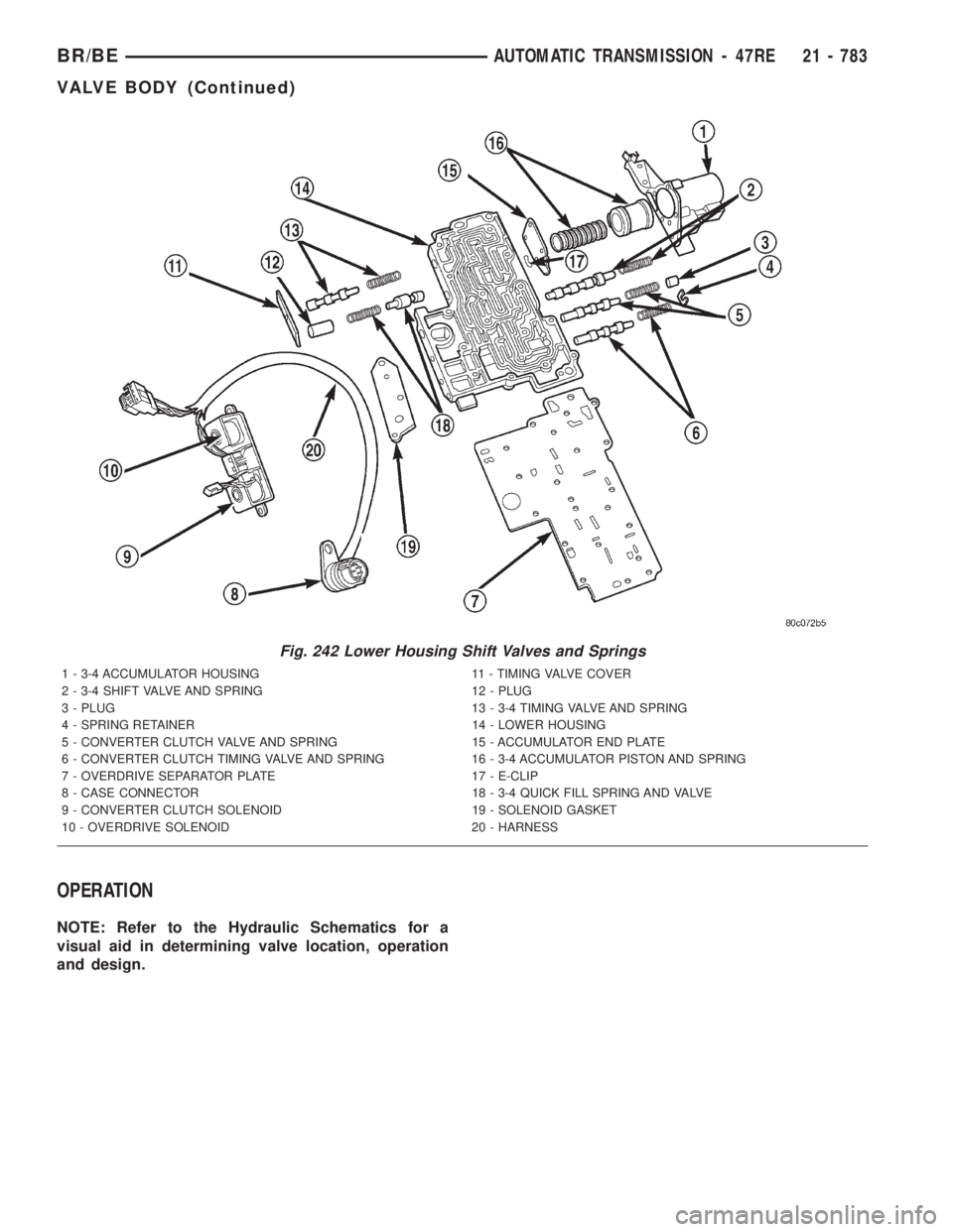
following components (Fig. 239), (Fig. 240), (Fig.
241), and (Fig. 242):
²Regulator valve
²Regulator valve throttle pressure plug
²Line pressure plug and sleeve
²Kickdown valve
²Kickdown limit valve
²1-2 shift valve
²1-2 control valve
²2-3 shift valve²2-3 governor plug
²3-4 shift valve
²3-4 timing valve
²3-4 quick fill valve
²3-4 accumulator
²Throttle valve
²Throttle pressure plug
²Switch valve
²Manual valve
²Converter clutch lock-up valve
²Converter clutch lock-up timing Valve
²Shuttle valve
²Shuttle valve throttle plug
²Boost Valve
²10 check balls
By adjusting the spring pressure acting on the reg-
ulator valve, transmission line pressure can be
adjusted.
Fig. 239 Upper Housing Control Valve Locations
1 - UPPER HOUSING 8 - MANUAL VALVE
2 - REGULATOR VALVE 9 - 1-2 GOVERNOR PLUG
3 - SWITCH VALVE 10 - GOVERNOR PLUG COVER
4 - REGULATOR VALVE SPRING 11 - THROTTLE PLUG
5 - KICKDOWN VALVE 12 - 2-3 GOVERNOR PLUG
6 - KICKDOWN DETENT 13 - SHUTTLE VALVE PRIMARY SPRING
7 - THROTTLE VALVE AND SPRING
21 - 780 AUTOMATIC TRANSMISSION - 47REBR/BE
Page 2416 of 2889
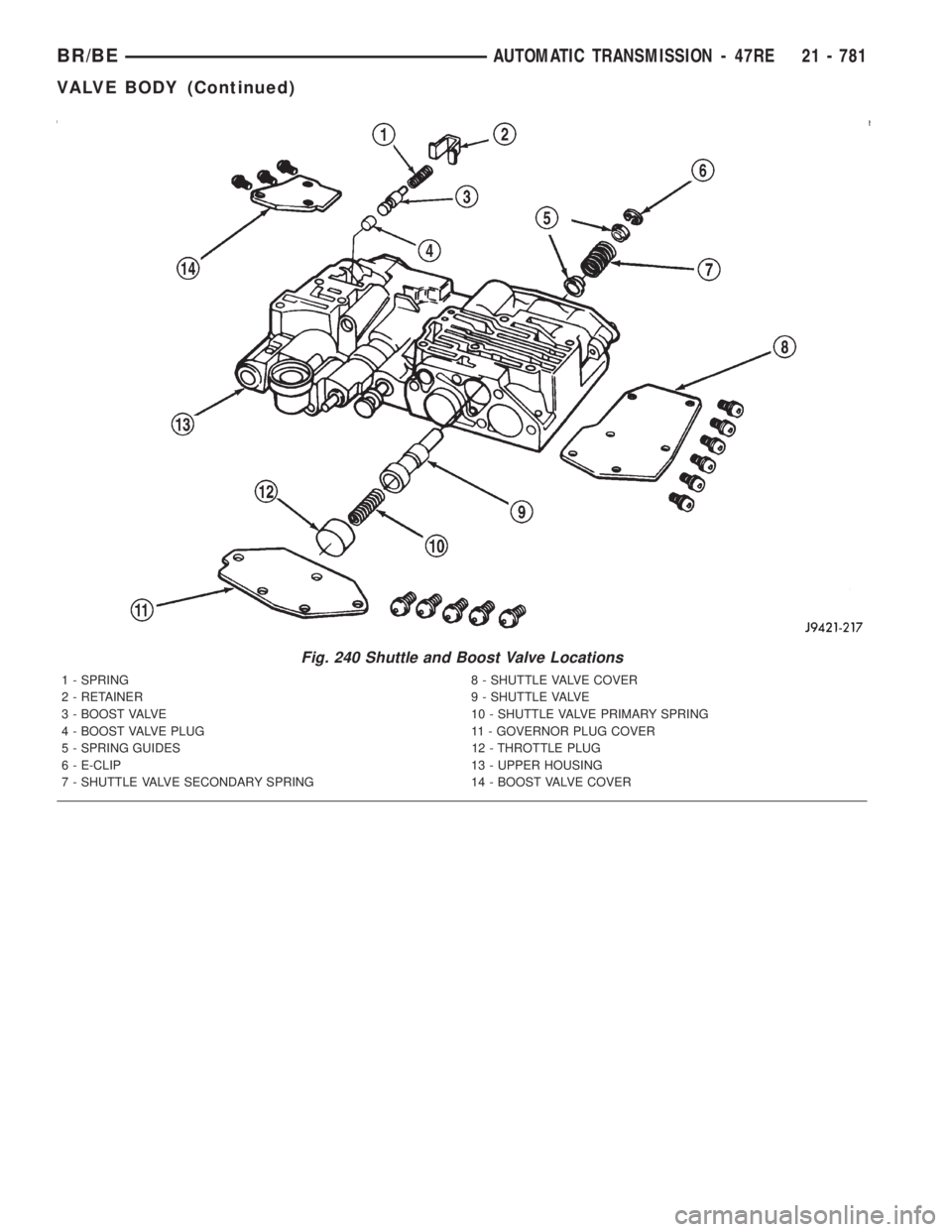
Fig. 240 Shuttle and Boost Valve Locations
1 - SPRING 8 - SHUTTLE VALVE COVER
2 - RETAINER 9 - SHUTTLE VALVE
3 - BOOST VALVE 10 - SHUTTLE VALVE PRIMARY SPRING
4 - BOOST VALVE PLUG 11 - GOVERNOR PLUG COVER
5 - SPRING GUIDES 12 - THROTTLE PLUG
6 - E-CLIP 13 - UPPER HOUSING
7 - SHUTTLE VALVE SECONDARY SPRING 14 - BOOST VALVE COVER
BR/BEAUTOMATIC TRANSMISSION - 47RE 21 - 781
VALVE BODY (Continued)
Page 2417 of 2889
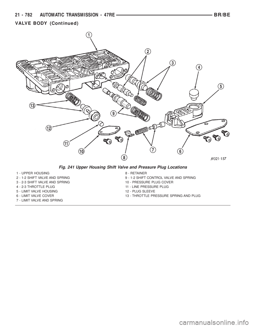
Fig. 241 Upper Housing Shift Valve and Pressure Plug Locations
1 - UPPER HOUSING 8 - RETAINER
2 - 1-2 SHIFT VALVE AND SPRING 9 - 1-2 SHIFT CONTROL VALVE AND SPRING
3 - 2-3 SHIFT VALVE AND SPRING 10 - PRESSURE PLUG COVER
4 - 2-3 THROTTLE PLUG 11 - LINE PRESSURE PLUG
5 - LIMIT VALVE HOUSING 12 - PLUG SLEEVE
6 - LIMIT VALVE COVER 13 - THROTTLE PRESSURE SPRING AND PLUG
7 - LIMIT VALVE AND SPRING
21 - 782 AUTOMATIC TRANSMISSION - 47REBR/BE
VALVE BODY (Continued)
Page 2418 of 2889
OPERATION
NOTE: Refer to the Hydraulic Schematics for a
visual aid in determining valve location, operation
and design.
Fig. 242 Lower Housing Shift Valves and Springs
1 - 3-4 ACCUMULATOR HOUSING 11 - TIMING VALVE COVER
2 - 3-4 SHIFT VALVE AND SPRING 12 - PLUG
3 - PLUG 13 - 3-4 TIMING VALVE AND SPRING
4 - SPRING RETAINER 14 - LOWER HOUSING
5 - CONVERTER CLUTCH VALVE AND SPRING 15 - ACCUMULATOR END PLATE
6 - CONVERTER CLUTCH TIMING VALVE AND SPRING 16 - 3-4 ACCUMULATOR PISTON AND SPRING
7 - OVERDRIVE SEPARATOR PLATE 17 - E-CLIP
8 - CASE CONNECTOR 18 - 3-4 QUICK FILL SPRING AND VALVE
9 - CONVERTER CLUTCH SOLENOID 19 - SOLENOID GASKET
10 - OVERDRIVE SOLENOID 20 - HARNESS
BR/BEAUTOMATIC TRANSMISSION - 47RE 21 - 783
VALVE BODY (Continued)
Page 2419 of 2889
CHECK BALLS
CHECK BALL NUMBER DESCRIPTION
1 Allows either the manual valve to put line pressure on the 1-2 governor plug or
the KD Valve to put WOT line pressure on the 1-2 governor plug.
2 Allows either the manual valve to put line pressure on the 2-3 governor plug or
the KD Valve to put WOT line pressure on the 2-3 governor plug.
3 Allows either the Reverse circuit or the 3rd gear circuit to pressurize the front
clutch.
4 Allows either the Manual Low circuit from the Manual Valve or the Reverse
from the Manual Valve circuit to pressurize the rear servo.
5 Directs line pressure to the spring end of the 2-3 shift valve in either Manual
Low or Manual 2nd, forcing the downshift to 2nd gear regardless of governor
pressure.
6 Provides a by-pass around the front servo orifice so that the servo can release
quickly.
7 Provides a by-pass around the rear clutch orifice so that the clutch can release
quickly.
8 Directs reverse line pressure through an orifice to the throttle valve eliminating
the extra leakage and insuring that Reverse line pressure pressure will be
sufficient.
9 Provides a by-pass around the rear servo orifice so that the servo can release
quickly.
ECE (10) Allows the lockup clutch to used at WOT in 3rd gear by putting line pressure
from the 3-4 Timing Valve on the interlock area of the 2-3 shift valve, thereby
preventing a 3rd gear Lock-up to 2nd gear kickdown.
REGULATOR VALVE
The pressure regulator valve is needed to control
the hydraulic pressure within the system and reduce
the amount of heat produced in the fluid. The pres-
sure regulator valve is located in the valve body near
the manual valve. The pressure regulator valve train
controls the maximum pressure in the lines by
metering the dumping of fluid back into the sump.
Regulated pressure is referred to as ªline pressure.º
The regulator valve (Fig. 243) has a spring on one
end that pushes the valve to the left. This closes a
dump (vent) that is used to lower pressure. The clos-
ing of the dump will cause the oil pressure to
increase. Oil pressure on the opposite end of the
valve pushes the valve to the right, opening the
dump and lowering oil pressure. The result is spring
pressure working against oil pressure to maintain
the oil at specific pressures. With the engine run-
ning, fluid flows from the pump to the pressure reg-
ulator valve, manual valve, and the interconnected
circuits. As fluid is sent through passages to the reg-
ulator valve, the pressure pushes the valve to the
right against the large spring. It is also sent to the
reaction areas on the left side of the throttle pressure
plug and the line pressure plug. With the gear selec-tor in the PARK position, fluid recirculates through
the regulator and manual valves back to the sump.
Meanwhile, the torque converter is filled slowly. In
all other gear positions (Fig. 244), fluid flows
between two right side lands to the switch valve and
torque converter. At low pump speeds, the flow is
controlled by the pressure valve groove to reduce
pressure to the torque converter. After the torque
converter and switch valve fill with fluid, the switch
valve becomes the controlling metering device for
torque converter pressure. The regulator valve then
begins to control the line pressure for the other
transmission circuits. The balance of the fluid pres-
sure pushing the valve to the right and the spring
pressure pushing to the left determines the size of
the metering passage at land #2 (land #1 being at
the far right of the valve in the diagram). As fluid
leaks past the land, it moves into a groove connected
to the filter or sump. As the land meters the fluid to
the sump, it causes the pressure to reduce and the
spring decreases the size of the metering passage.
When the size of the metering passage is reduced,
the pressure rises again and the size of the land is
increased again. Pressure is regulated by this con-
stant balance of hydraulic and spring pressure.
21 - 784 AUTOMATIC TRANSMISSION - 47REBR/BE
VALVE BODY (Continued)
Page 2420 of 2889
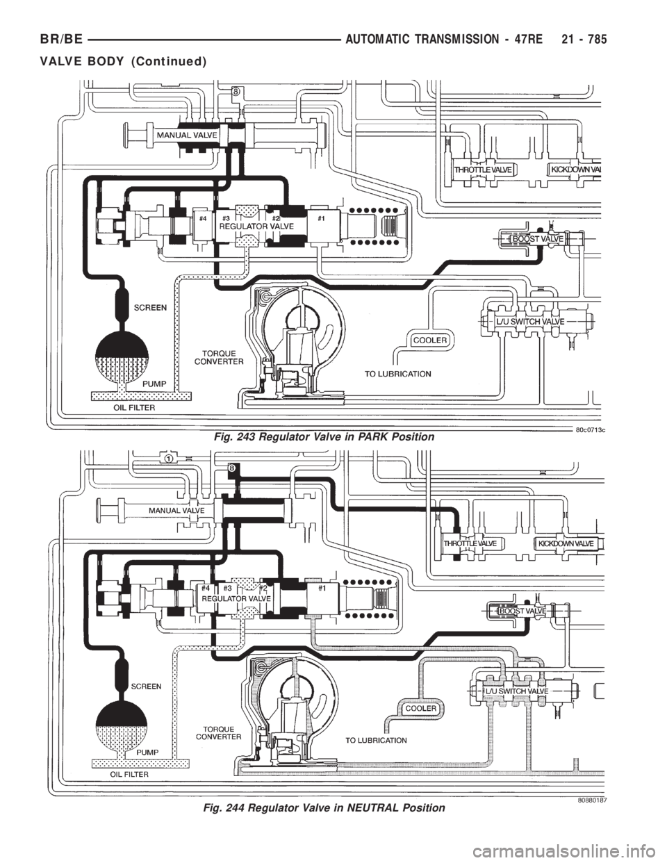
Fig. 243 Regulator Valve in PARK Position
Fig. 244 Regulator Valve in NEUTRAL Position
BR/BEAUTOMATIC TRANSMISSION - 47RE 21 - 785
VALVE BODY (Continued)