DODGE RAM SRT-10 2006 Service Repair Manual
Manufacturer: DODGE, Model Year: 2006, Model line: RAM SRT-10, Model: DODGE RAM SRT-10 2006Pages: 5267, PDF Size: 68.7 MB
Page 891 of 5267
*IN-TANK FUEL LIFT PUMP FLOW/DIAGNOSTIC TEST PROCEDURE
Diagnostic Test
Page 892 of 5267
1.
1. Using the Scan tool, check for DTCs. Troubleshoot any active DTCs beforeperforming this test.
2. Disconnect the wiring harness from the lift pump at the fuel tank module connector and inspect the pins for
damage. Fix or replace any damaged component.
3. Connect a voltmeter between the fuel lift pump supply and return pins at the fuel tank module connector.
4. Turn the ignition to the on position. Use the Scan tool to actuate the fuellift pump, record the voltage on the
voltmeter.
5. If the voltage is greater than 11.5 volts, go to step 14. If the voltage is lessthan11.5volts,gotostep6
6. Using a voltmeter, measure the battery voltage to determine that the voltage is greater than 11.5 volts. If the
voltage is greater than 11.5 volts, go to step 7. If the voltage is not greater than 11.5 volts, troubleshoot for low
battery voltage.
7. Remove the fuel lift pump relay from the PDC. Use a voltmeter to measure the voltage at the fuel lift pump relay
voltage supply pin in the PDC. If the voltage is greater than 11.5 volts, go to step 8. If the voltage is not greater than
11.5 volts, fix or replace the harness.
8. Remove the fuel lift pump relay from the PDC. Install a spare relay in place of the fuel lift pump relay. Using the
Scan tool, actuate the fuel lift pump. Use a voltmeter to measure the voltage between the fuel lift pump supply and
return pins at the fuel tank module connector while the fuel lift pump is actuated. If the voltage is greater than 11.5
volts, replace the fuel lift pump relay. If the voltage is not greater than 11.5volts,gotostep9.
9. Disconnect the wiring harness from the fuel tank module. Remove the liftpump relay from the PDC. Using an
Ohmmeter, measure the resistance of the fuel lift pump power supply wire between the PDC relay output pin and
the fuel tank module connector. If the resistance is less than 10 ohms, go tostep 10. If it is greater than 10 ohms,
fix or replace the harness.
10. Disconnect the wiring harness from the fuel tank module. Remove the fuel lift pump relay from the PDC. Using
a voltmeter, measure the voltage between battery negative and the fuel lift pump power supply wire at the fuel
module connector. If the voltage is less than 1 volt, go to step 11. If the voltage is greater than 1 volt, fix or replace
the harness.
11. Disconnect the wiring harness from the fuel tank module. Remove the fuel lift pump relay from the PDC. Using
an ohmmeter, measure the resistance between battery negative and the fuellift pump power supply wire at the fuel
module connector. If the resistance is less than 10 ohms, fix or replace theharness. If the resistance is greater than
10 ohms, go to step 12.
12. Disconnect the wiring harness from the fuel tank module. Using an Ohmmeter, measure the resistance of the
fuel lift pump ground wire between the fuel tank module connector and battery negative. If the resistance is less
than 10 ohms, go to step 13. If the resistance is greater than 10 ohms, fix or replace the harness.
13. Disconnect the wiring harness from the fuel tank module. Using a voltmeter, measure the voltage between the
fuel lift pump ground wire and battery negative. If the voltage is less than1 volt, go to step 14. If the voltage is
greater than 1 volt, fix or replace the harness.
14. Reconnect the lift pump connector.
FLOW TEST.
1. Remove the fuel pump supply banjo fitting from the fuel injection pump.
2. Install Miller Tool #9014 fuel system test fitting into the fuel injection pump.
3. Connect one end of a section of fuel hose to the test fitting.
4. Put the other end of the fuel hose into an empty fuel container.
5. Use the scan tool to actuate the fuel lift pump.
6. While the lift pump is running, move the fuel hose from the fuel canister into a 1000ml graduated cylinder for 10
seconds.
7. Read and record the amount of fuel in the graduated cylinder after 10 seconds.
8. If you have more than 430ml in the graduated cylinder after 10 seconds, the test has successfully passed.
9. If you have less than 430ml of fuel in the graduated cylinder, inspect thefuel supply line from the fuel tank to the
fuel filter housing and the fuel supply line between the fuel filter housing and the high pressure fuel pump for signs
of damage, replace as necessary. If no damage is found, replace the fuel filter and retest.
10.Verify the Screened Banjo Bolt at the outlet of the fuel filter is free ofdebris. If debris is found, rinse screen with
water, blow dry and reinstall. Retest vehicle. If flow meets specification then trace back the source of debris, if flow
is still below spec repair damaged component.
Page 893 of 5267
11. If reading is still less than 430ml in 10 seconds, remove the fuel tank and fuel tank module. Inspect for damage
and/or debris in and around the fuel tank module. If module is damaged, replace and retest.
12. If the module is not damaged, replace the fuel lift pump and retest to confirm fix.
Test complete
Repair
Te s t c o m p l e t e .
Perform POWERTRAIN VERIFICATION TEST VER - 1 (DIESEL). (Refer to 8 - ELECTRICAL/ELEC-
TRONIC CONTROL MODULES/ENGINE CONTROL MODULE - DIAGNOSIS AND TESTING)
Page 894 of 5267
*FUEL PUMP RETURN FLOW TEST
Possible Causes
EXCESSIVE FUEL PUMP RETURN FLOW
Diagnostic Test
1.FUEL PUMP RETURN FLOW TEST
Using the scan tool, idle the engine and measure the rail pressure and determine if the rail pressure is excessive
(above 185,00 kpa/26,831 psi), if it is, troubleshoot for excessive rail pressure first.
Remove the banjo bolt from the pressure-limiting valve on the fuel rail.
Install fuel system test fitting #9013 into the pressure-limiting valve.
Attach one end of a fuel hose to the fuel fitting and put the other end of the fuel hose into a container
Perform the tests listed below to determine if the pressure-limiting valve is leaking.
a. Operate the engine at idle and watch for fuel flow into the fuel container.
b. Operate the engine at idle and actuate the high pressure safety valve test with the scan tool. Watch for fuel flow
into the fuel container.
If fuel flows into the fuel container, replace the pressure-limiting valve. If fuel does not leak from the pressure-limiting
valve, the test is complete.
NOTE: do not drive the vehicle with any portion of this test kit installed
Operate the engine until the engine is at operating temperature.
Remove the banjo connector from the fuel drain tube at the rear of the fuel filter housing
Install fuel system test fitting #9012 in place of the banjo connector.
Install a piece of fuel line onto the test fitting and put the open end into the graduated cylinder.
Start the engine and let it idle for one minute.
Measure the amount of fuel in the graduated cylinder.
If the flow is less than 1000-ml/minute at idle, the test has successfully passed.
If the flow is greater than 1000 ml/minute at idle, replace the fuel injection pump.
Retest to confirm repair.
View Repair
Repair
Te s t C o m p l e t e .
Perform POWERTRAIN VERIFICATION TEST VER - 1 (DIESEL). (Refer to 8 - ELECTRICAL/ELEC-
TRONIC CONTROL MODULES/ENGINE CONTROL MODULE - DIAGNOSIS AND TESTING)
Page 895 of 5267
*HIGH PRESSURE FUEL PUMP PERFORMANCE TEST
Diagnostic Test
1.
If the engine will run do the following:
1. Monitor rail pressure with scan tool while the engine is at idle.
2. Compare the fuel pressure set point with the actual fuel pressure reading.
3. If actual fuel pressure reading fluctuates more than +/- 500 psi from theset point, then replace the Fuel Conrol
Actuator (FCA). NOTE: After the acutator is removed, check for debris or corrosion on the FCA. If debris or corro-
sion is found, replace the entire Fuel Injection Pump.
4. Turn off engine.
5. Disconnect the FCA harness
6. Disconnect high pressure fuel line from fuel rail and route the high pressure fuel line into a graduated cylinder.
7. Crank the engine until fuel exits this line. This will not be high pressurefuel.
8. Crank the engine for three (3) 10 second intervals (Note: This will give you 30 total seconds of flow time. These
are broken into 3 separate intervals to prevent damage to the starter). Fuel flow specification s based on engine
cranking speed. If you do not collect the stated amount of fuel in 30 seconds, replace the pump:
Minimum fuel pump flow at 150 rpm cranking speed is 70mL
Minimum fuel pump flow at 200 rpm cranking speed is 90mL
If the engine is a no start do the following:
1. Remove fuel pump to railhigh pressure fuel line.
2. Inspect the fuel pump outlet port for rust, debris, or other signs of contamination.
3. Replace pump if any contamination is found. Check for source of water in fuel or debris in fuel to prevent future
complaints. If no contamination is found continue to step 4.
4. Disconnect the Fuel Control Actuator (FCA).
5. Disconnect the high pressure fuel line from the fuel rail and route the high pressure fuel line to a graduated
cylinder.
6. Crank the engine until fuel exits this line. This will not be high pressurefuel.
7. Crank the engine for three (3) 10 seconds intervals.
NOTE: This will give you 30 total seconds of flow time. These are broken into3 separate intervals to pre-
vent damage to the starter.
Fuel flow specification’s based on engine cranking speed. If you do not collect the stated amount of fuel in 30
seconds, replace the pump:
Minimum fuel pump flow at 150 rpm cranking speed is 70mL
Minimum fuel pump flow at 200 rpm cranking speed is 90mL
Test complete
Repair
Te s t c o m p l e t e .
Perform POWERTRAIN VERIFICATION TEST VER - 1 (DIESEL). (Refer to 8 - ELECTRICAL/ELEC-
TRONIC CONTROL MODULES/ENGINE CONTROL MODULE - DIAGNOSIS AND TESTING)
Page 896 of 5267
*INJECTOR RETURN FLOW TEST
Diagnostic Test
1.* INJECTOR RETURN FLOW TEST
1. Operate the engine until the engine is at operating temperature.
2. Remove the banjo connector from the fuel drain tube at the rear of the fuelfilter housing.
3. Install fuel system test fitting (9012) in place of the banjo connector.
4. Remove the vehicle fuel return line from the engine fuel drain tube. Route this hose into a container to catch bled
fuel.
5. Install a piece of fuel line onto the test fitting and into a fuel container or into the fuel tank.
6. Install one end of a test hose onto the fuel drain tube. Place the other endof the test hose into a graduated
cylinder.
7. Start the engine and let it idle for one minute.
8. Measure the amount of fuel in the graduated cylinder.
9. If the flow is less than 180-ml/minute, the test has successfully passed.
10. If the flow is greater than 180 ml/minute, shut off the engine and removeall of the fuel injector supply lines. Re
torque all of the high-pressure connector nuts. Install all of the fuel injector supply lines.
11. Start the engine and idle for one minute. Measure the amount of fuel in the graduated cylinder.
12. If the flow is less than 180ml/minute, the condition has been fixed.
13. If the flow is greater than 180 ml/minute after step 12, shut off the engine and remove the #1 fuel injector supply
line. Re torque the high-pressure connector nut. Cap the #1 fuel port usingtool #9011 on the fuel rail and the #1
high pressure connector.
14. Start the engine. Measure the amount of fuel in the graduated cylinder.
15. If the amount of fuel is less than 180 ml/minute, shut off the engine and remove the #1 high pressure connector
and the #1 fuel injector. Inspect for damage, repair/replace as necessary.
16. If the amount of fuel is not less than 180-ml/minute, repeat steps 14-16for cylinders 2-6.
17. Install all high-pressure connectors, fuel injectors, and fuel injector supply lines. Repeat steps 1-8 to confirm
repair.
SPECIFICATION:Less than 180 ml/minute total fuel return flow
Repair
Te s t C o m p l e t e .
Perform POWERTRAIN VERIFICATION TEST VER - 1 (DIESEL). (Refer to 8 - ELECTRICAL/ELEC-
TRONIC CONTROL MODULES/ENGINE CONTROL MODULE - DIAGNOSIS AND TESTING)
Page 897 of 5267
*INTAKE AIR SYSTEM PRESSURE TEST
Diagnostic Test
1.CHARGE AIR COOLER PRESSURE TEST
Loosen air inlet tube clamp at the turbocharger.
Remove the air filter housing and the inlet tube from the vehicle as an assembly.
Install the CAC Pressure Tester #9022 into the inner diameter of the turbocharger, securing it in place with the
supplied three-fingered band clamp, tighten tool clamp to 8n.m (72 in lbs).
NOTE: NEVER ATTEMPT TO START OR RUN THE VEHICLE AT ANY TIME DURING THIS TEST,ENGINE DAM-
AGE MAY OCCUR.
Fasten the safety chain around a solid surface behind the turbocharger. Warning: Never run CAC Pressure test
without the safety chain securely fastened.
Before attaching shop air to the pressure regulator verify that the regulator is at its lowest pressure setting (0 psi).
Attach an air supply to the regulator and slowly increase the pressure until the pressure gauge reads 20 psi.
WARNING: WARNING: Never apply more than 20 PSI.
Using a solution of soap and water spray the Turbocharger, Turbocharger wastegate, Charge Air Cooler Heat
Exchange and CAC Hoses while watching for leaks.
Before any attempt to repair the CAC system is made, its necessary to completely discharge the system. This can
be accomplished by turning the regulator knob counter-clockwise.
Allow for adequate time to pass before removing the CAC Pressure tester from the turbo charger inlet.
Position the Air Filter Housing over thethreemountingstudslocatedonthe inside front fender well and press down
firmly to lock housing into place.
Install Air Inlet Tube over the Turbocharger inlet and torque the band clampto35in.lbs.
View Repair
Repair
Te s t c o m p l e t e .
Perform POWERTRAIN VERIFICATION TEST VER - 1 (DIESEL). (Refer to 8 - ELECTRICAL/ELEC-
TRONIC CONTROL MODULES/ENGINE CONTROL MODULE - DIAGNOSIS AND TESTING)
Page 898 of 5267
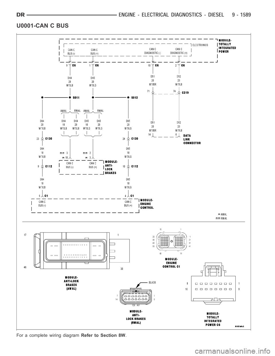
U0001-CAN C BUS
For a complete wiring diagramRefer to Section 8W.
Page 899 of 5267
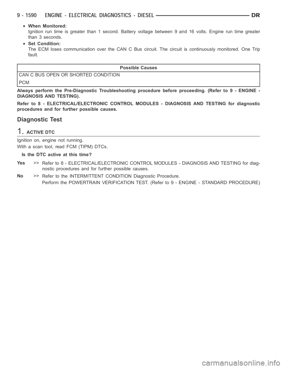
When Monitored:
Ignition run time is greater than 1 second. Battery voltage between 9 and 16volts. Engine run time greater
than 3 seconds.
Set Condition:
The ECM loses communication over the CAN C Bus circuit. The circuit is continuously monitored. One Trip
fault.
Possible Causes
CAN C BUS OPEN OR SHORTED CONDITION
PCM
Always perform the Pre-Diagnostic Troubleshooting procedure before proceeding. (Refer to 9 - ENGINE -
DIAGNOSIS AND TESTING).
Refer to 8 - ELECTRICAL/ELECTRONIC CONTROL MODULES - DIAGNOSIS AND TESTING for diagnostic
procedures and for further possible causes.
Diagnostic Test
1.ACTIVE DTC
Ignition on, engine not running.
With a scan tool, read FCM (TIPM) DTCs.
Is the DTC active at this time?
Ye s>>
Refer to 8 - ELECTRICAL/ELECTRONIC CONTROL MODULES - DIAGNOSIS AND TESTING for diag-
nostic procedures and for further possible causes.
No>>
Refer to the INTERMITTENT CONDITION Diagnostic Procedure.
Perform the POWERTRAIN VERIFICATION TEST. (Refer to 9 - ENGINE - STANDARD PROCEDURE)
Page 900 of 5267
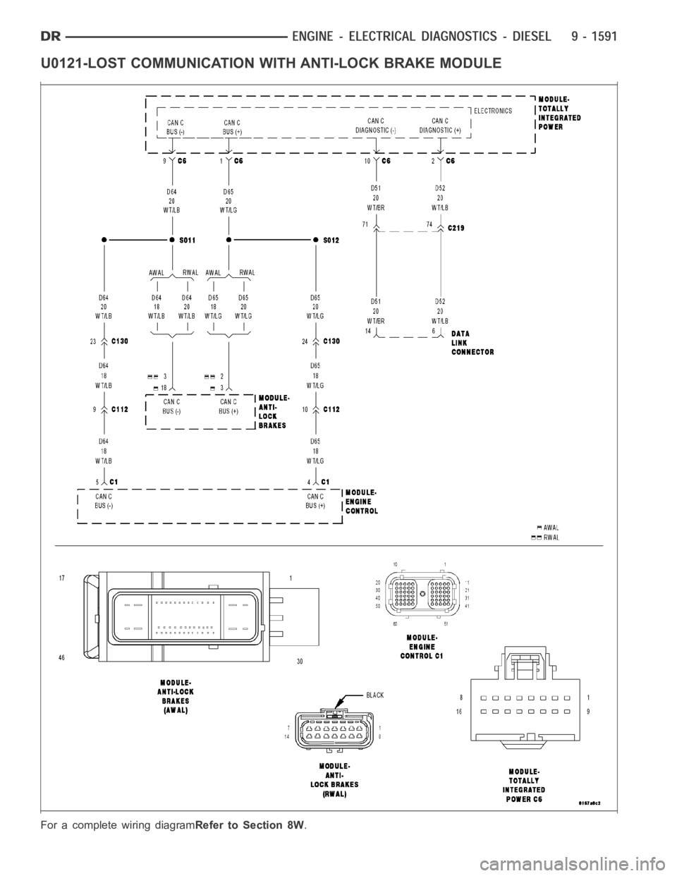
U0121-LOST COMMUNICATION WITH ANTI-LOCK BRAKE MODULE
For a complete wiring diagramRefer to Section 8W.