DODGE RAM SRT-10 2006 Service Repair Manual
Manufacturer: DODGE, Model Year: 2006, Model line: RAM SRT-10, Model: DODGE RAM SRT-10 2006Pages: 5267, PDF Size: 68.7 MB
Page 931 of 5267
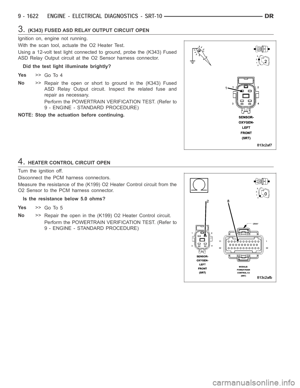
3.(K343) FUSED ASD RELAY OUTPUT CIRCUIT OPEN
Ignition on, engine not running.
With the scan tool, actuate the O2 Heater Test.
Using a 12-volt test light connected to ground, probe the (K343) Fused
ASD Relay Output circuit at the O2 Sensor harness connector.
Did the test light illuminate brightly?
Ye s>>
Go To 4
No>>
Repair the open or short to ground in the (K343) Fused
ASD Relay Output circuit. Inspect the related fuse and
repair as necessary.
Perform the POWERTRAIN VERIFICATION TEST. (Refer to
9 - ENGINE - STANDARD PROCEDURE)
NOTE: Stop the actuation before continuing.
4.HEATER CONTROL CIRCUIT OPEN
Turn the ignition off.
Disconnect the PCM harness connectors.
Measure the resistance of the (K199) O2 Heater Control circuit from the
O2 Sensor to the PCM harness connector.
Is the resistance below 5.0 ohms?
Ye s>>
Go To 5
No>>
Repair the open in the (K199) O2 Heater Control circuit.
Perform the POWERTRAIN VERIFICATION TEST. (Refer to
9 - ENGINE - STANDARD PROCEDURE)
Page 932 of 5267
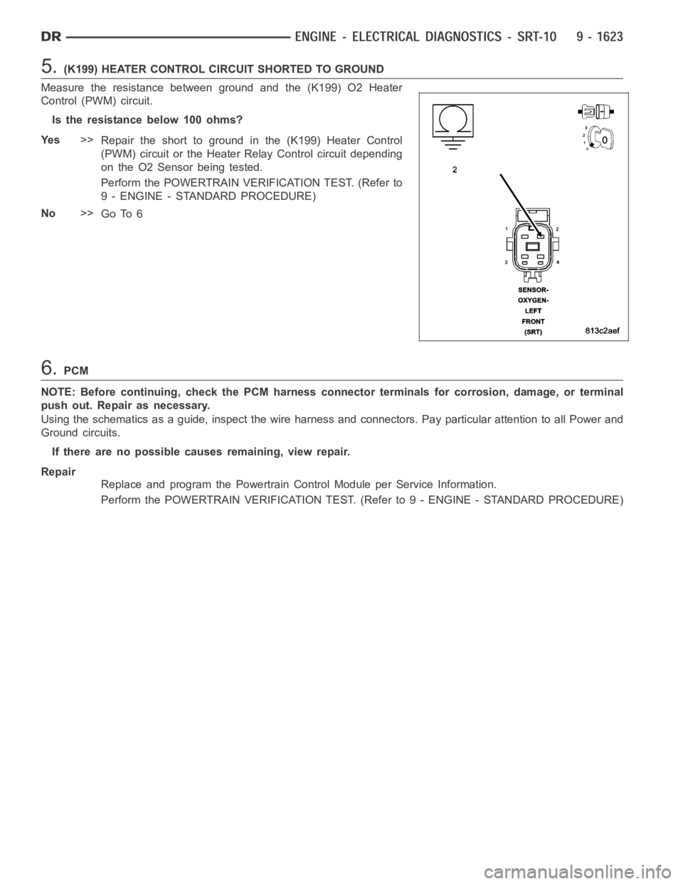
5.(K199) HEATER CONTROL CIRCUIT SHORTED TO GROUND
Measure the resistance between ground and the (K199) O2 Heater
Control (PWM) circuit.
Istheresistancebelow100ohms?
Ye s>>
Repair the short to ground in the (K199) Heater Control
(PWM) circuit or the Heater Relay Control circuit depending
on the O2 Sensor being tested.
Perform the POWERTRAIN VERIFICATION TEST. (Refer to
9 - ENGINE - STANDARD PROCEDURE)
No>>
Go To 6
6.PCM
NOTE: Before continuing, check the PCM harness connector terminals for corrosion, damage, or terminal
push out. Repair as necessary.
Using the schematics as a guide, inspect the wire harness and connectors. Pay particular attention to all Power and
Ground circuits.
If there are no possible causes remaining, view repair.
Repair
Replace and program the Powertrain Control Module per Service Information.
Perform the POWERTRAIN VERIFICATION TEST. (Refer to 9 - ENGINE - STANDARD PROCEDURE)
Page 933 of 5267

P0071-AMBIENT/BATTERY TEMP SENSOR PERFORMANCE
For a complete wiring diagramRefer to Section 8W.
Page 934 of 5267
When Monitored:
With the ignition on and no Battery Temperature Sensor Open or Short Faultspresent.
Set Condition:
After 5 warm cycles have occurred (coolant increases at least 22°C (40°F) to a minimum of 71°C (160°F) and
the odometer mileage has increased 196.6 miles and the Battery Temperature has changed less than 4°C
(7.2°F) change in temperature. One trip fault.
Possible Causes
GOOD TRIP EQUAL TO ZERO
(K25) BATTERY TEMP SIGNAL CIRCUIT SHORTED TO VOLTAGE
BATTERY TEMPERATURE SENSOR
RESISTANCE IN THE (K25) BATTERY TEMP SENSOR SIGNAL CIRCUIT
RESISTANCE IN THE (K900) SENSOR GROUND CIRCUIT
(K25) BATTERY TEMP SENSOR SIGNAL CIRCUIT SHORTED TO GROUND
PCM
Always perform the Pre-Diagnostic Troubleshooting procedure before proceeding. (Refer to 9 - ENGINE -
DIAGNOSIS AND TESTING)
1.GOOD TRIP EQUAL TO ZERO
Ignition on, engine not running.
With the scan tool, read DTCs and record the related Freeze Frame data.
Is the Good Trip Counter equal to zero?
Ye s>>
Go To 2
No>>
Refer to the INTERMITTENT CONDITION Symptom. (Refer to 9 - ENGINE - DIAGNOSIS AND TEST-
ING)
2.(K25) BATTERY TEMP SIGNAL CIRCUIT SHORTED TO VOLTAGE
Turn the ignition off.
Disconnect the Battery Temp Sensor harness connector.
Ignition on, engine not running.
Measure the voltage on the (K25) Battery Temp Signal circuit at the
Sensor connector.
Is the voltage above 5.2 volts?
Ye s>>
Repair the short to voltage on the (K25) Batt Temp Signal
circuit.
Perform POWERTRAIN VERIFICATION TEST. (Refer to 9 -
ENGINE - STANDARD PROCEDURE)
No>>
Go To 3
Page 935 of 5267
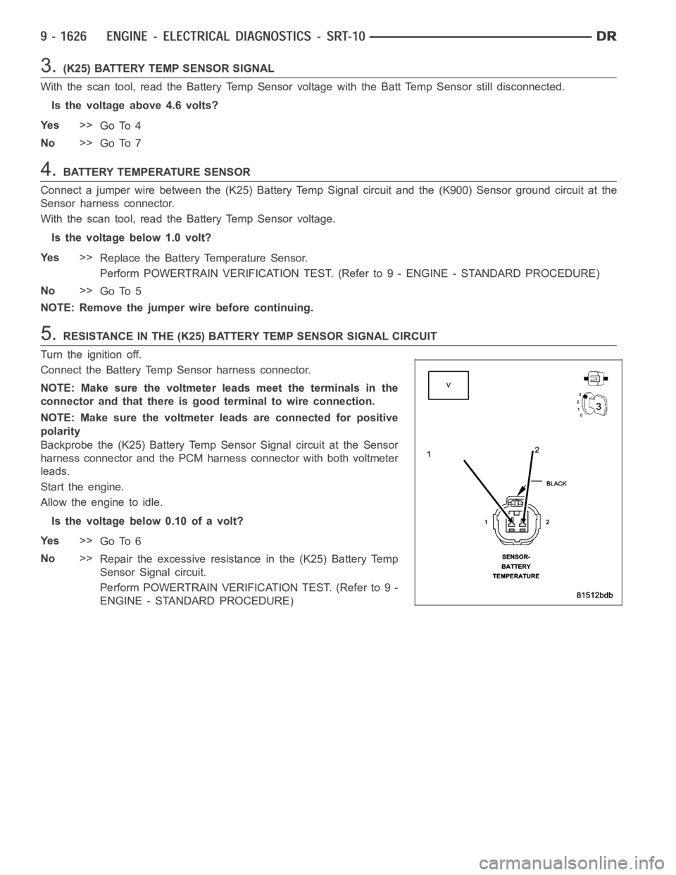
3.(K25) BATTERY TEMP SENSOR SIGNAL
With the scan tool, read the Battery Temp Sensor voltage with the Batt Temp Sensor still disconnected.
Is the voltage above 4.6 volts?
Ye s>>
Go To 4
No>>
Go To 7
4.BATTERY TEMPERATURE SENSOR
Connect a jumper wire between the (K25) Battery Temp Signal circuit and the(K900) Sensor ground circuit at the
Sensor harness connector.
With the scan tool, read the Battery Temp Sensor voltage.
Is the voltage below 1.0 volt?
Ye s>>
Replace the Battery Temperature Sensor.
Perform POWERTRAIN VERIFICATION TEST. (Refer to 9 - ENGINE - STANDARD PROCEDURE)
No>>
Go To 5
NOTE: Remove the jumper wire before continuing.
5.RESISTANCE IN THE (K25) BATTERY TEMP SENSOR SIGNAL CIRCUIT
Turn the ignition off.
Connect the Battery Temp Sensor harness connector.
NOTE: Make sure the voltmeter leads meet the terminals in the
connector and that there is good terminal to wire connection.
NOTE: Make sure the voltmeter leads are connected for positive
polarity
Backprobe the (K25) Battery Temp Sensor Signal circuit at the Sensor
harness connector and the PCM harness connector with both voltmeter
leads.
Start the engine.
Allow the engine to idle.
Is the voltage below 0.10 of a volt?
Ye s>>
Go To 6
No>>
Repair the excessive resistance in the (K25) Battery Temp
Sensor Signal circuit.
Perform POWERTRAIN VERIFICATION TEST. (Refer to 9 -
ENGINE - STANDARD PROCEDURE)
Page 936 of 5267
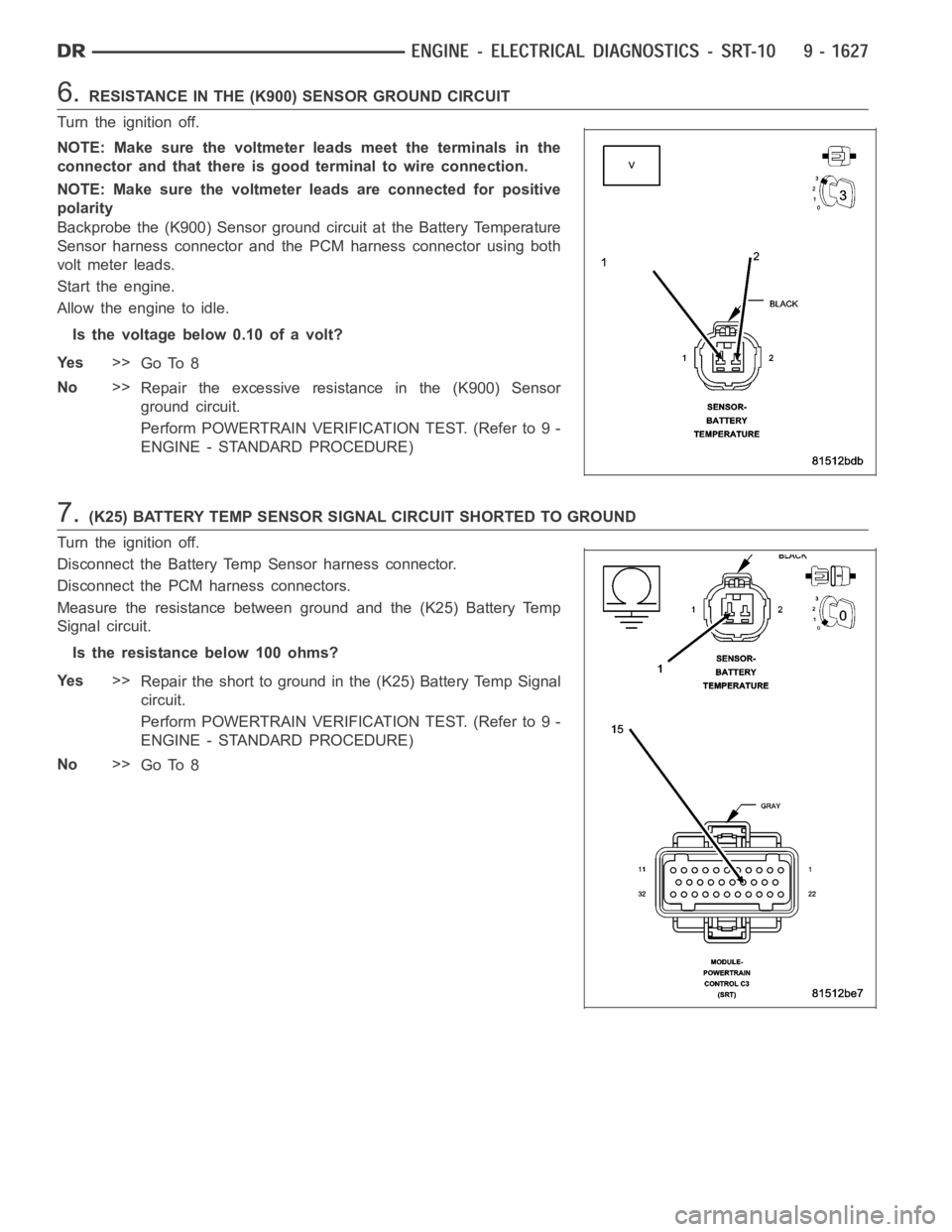
6.RESISTANCE IN THE (K900) SENSOR GROUND CIRCUIT
Turn the ignition off.
NOTE: Make sure the voltmeter leads meet the terminals in the
connector and that there is good terminal to wire connection.
NOTE: Make sure the voltmeter leads are connected for positive
polarity
Backprobe the (K900) Sensor ground circuit at the Battery Temperature
Sensor harness connector and the PCM harness connector using both
volt meter leads.
Start the engine.
Allow the engine to idle.
Is the voltage below 0.10 of a volt?
Ye s>>
Go To 8
No>>
Repair the excessive resistance in the (K900) Sensor
ground circuit.
Perform POWERTRAIN VERIFICATION TEST. (Refer to 9 -
ENGINE - STANDARD PROCEDURE)
7.(K25) BATTERY TEMP SENSOR SIGNAL CIRCUIT SHORTED TO GROUND
Turn the ignition off.
Disconnect the Battery Temp Sensor harness connector.
Disconnect the PCM harness connectors.
Measure the resistance between ground and the (K25) Battery Temp
Signal circuit.
Istheresistancebelow100ohms?
Ye s>>
Repair the short to ground in the (K25) Battery Temp Signal
circuit.
Perform POWERTRAIN VERIFICATION TEST. (Refer to 9 -
ENGINE - STANDARD PROCEDURE)
No>>
Go To 8
Page 937 of 5267

8.PCM
NOTE: Before continuing, check the PCM harness connector terminals for corrosion, damage, or terminal
push out. Repair as necessary.
Using the schematics as a guide, inspect the wire harness and connectors. Pay particular attention to all Power and
Ground circuits.
If there are no possible causes remaining, view repair.
Repair
Replace and program the Powertrain Control Module per Service Information.
Perform POWERTRAIN VERIFICATION TEST. (Refer to 9 - ENGINE - STANDARD PROCEDURE)
Page 938 of 5267

P0107-MAP SENSOR VOLTAGE TOO LOW
For a complete wiring diagramRefer to Section 8W.
Page 939 of 5267
When Monitored:
With the engine RPM above 416 but less than 1500, the TPS voltage less than 1.13 volts, and battery voltage
greater than 10.4 volts.
Set Condition:
The MAP Sensor signal voltage is below 0.1 of a volt for 2.0 seconds with the engine running.
Possible Causes
(F855) 5-VOLT SUPPLY CIRCUIT OPEN
(F855) 5-VOLT SUPPLY CIRCUIT SHORTED TO GROUND
(K1) MAP SIGNAL CIRCUIT SHORTED TO GROUND
(K1) MAP SIGNAL CIRCUIT SHORTED TO THE (K900) SENSOR GROUND CIRCUIT
MAP SENSOR
PCM
Always perform the Pre-Diagnostic Troubleshooting procedure before proceeding. (Refer to 9 - ENGINE -
DIAGNOSIS AND TESTING).
Diagnostic Test
1.MAP SENSOR VOLTAGE BELOW 0.08 OF A VOLT
Ignition on, engine not running.
With a scan tool, read the MAP Sensor voltage.
Is the voltage below 0.08 of a volt?
Ye s>>
Go To 2
No>>
Refer to the INTERMITTENT CONDITION Diagnostic Procedure. (Refer to 9 - ENGINE - DIAGNOSIS
AND TESTING)
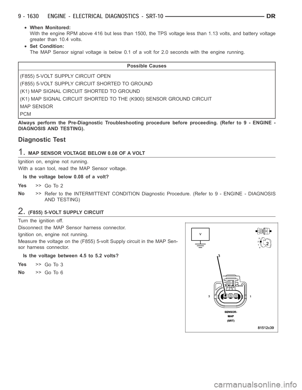
2.(F855) 5-VOLT SUPPLY CIRCUIT
Turn the ignition off.
Disconnect the MAP Sensor harness connector.
Ignition on, engine not running.
Measure the voltage on the (F855) 5-volt Supply circuit in the MAP Sen-
sor harness connector.
Is the voltage between 4.5 to 5.2 volts?
Ye s>>
Go To 3
No>>
Go To 6
Page 940 of 5267
3.MAP SENSOR
With a scan tool, monitor the MAP Sensor voltage with the Sensor harness connector disconnected.
Is the voltage above 4.5 volts?
Ye s>>
Replace the MAP Sensor.
Perform the POWERTRAIN VERIFICATION TEST. (Refer to 9 - ENGINE - STANDARD PROCEDURE)
No>>
Go To 4
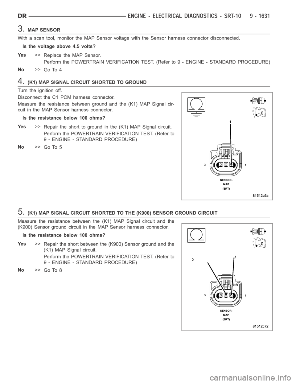
4.(K1) MAP SIGNAL CIRCUIT SHORTED TO GROUND
Turn the ignition off.
Disconnect the C1 PCM harness connector.
Measure the resistance between ground and the (K1) MAP Signal cir-
cuit in the MAP Sensor harness connector.
Istheresistancebelow100ohms?
Ye s>>
Repair the short to ground in the (K1) MAP Signal circuit.
Perform the POWERTRAIN VERIFICATION TEST. (Refer to
9 - ENGINE - STANDARD PROCEDURE)
No>>
Go To 5
5.(K1) MAP SIGNAL CIRCUIT SHORTED TO THE (K900) SENSOR GROUND CIRCUIT
Measure the resistance between the (K1) MAP Signal circuit and the
(K900) Sensor ground circuit in the MAP Sensor harness connector.
Istheresistancebelow100ohms?
Ye s>>
Repair the short between the (K900) Sensor ground and the
(K1) MAP Signal circuit.
Perform the POWERTRAIN VERIFICATION TEST. (Refer to
9 - ENGINE - STANDARD PROCEDURE)
No>>
Go To 8