DODGE RAM SRT-10 2006 Service Repair Manual
Manufacturer: DODGE, Model Year: 2006, Model line: RAM SRT-10, Model: DODGE RAM SRT-10 2006Pages: 5267, PDF Size: 68.7 MB
Page 911 of 5267
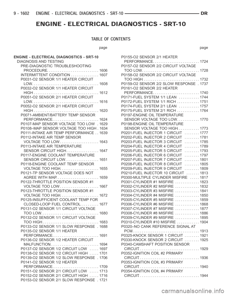
page page
ENGINE - ELECTRICAL DIAGNOSTICS - SRT-10
DIAGNOSIS AND TESTING
PRE-DIAGNOSTIC TROUBLESHOOTING
PROCEDURE............................. 1606
INTERMITTENT CONDITION ............... 1607
P0031-O2 SENSOR 1/1 HEATER CIRCUIT
LOW..................................... 1608
P0032-O2 SENSOR 1/1 HEATER CIRCUIT
HIGH.................................... 1612
P0051-O2 SENSOR 2/1 HEATER CIRCUIT
LOW..................................... 1616
P0052-O2 SENSOR 2/1 HEATER CIRCUIT
HIGH.................................... 1620
P0071-AMBIENT/BATTERY TEMP SENSOR
PERFORMANCE.......................... 1624
P0107-MAP SENSOR VOLTAGE TOO LOW . 1629
P0108–MAP SENSOR VOLTAGE TOO HIGH . 1634
P0111-INTAKE AIR TEMP PERFORMANCE . . 1639
P0112-INTAKE AIR TEMP SENSOR
VOLTAGE TOO LOW...................... 1643
P0113-INTAKE AIR TEMPERATURE
SENSOR CIRCUIT HIGH.................. 1647
P0117-ENGINE COOLANT TEMPERATURE
SENSOR CIRCUIT LOW................... 1651
P0118-ENGINE COOLANT TEMP SENSOR
VOLTAGE TOO HIGH...................... 1655
P0121-TP SENSOR VOLTAGE DOES NOT
AGREE WITH MAP........................ 1659
P0122-THROTTLE POSITION SENSOR #1
VOLTAGE TOO LOW...................... 1667
P0123-THROTTLE POSITION SENSOR #1
VOLTAGE TOO HIGH...................... 1672
P0125-INSUFFICIENT COOLANT TEMP FOR
CLOSED-LOOP FUEL CONTROL........... 1677
P0131-O2 SENSOR 1/1 CIRCUIT VOLTAGE
TOO LOW................................ 1680
P0132-O2 SENSOR 1/1 CIRCUIT VOLTAGE
TOO HIGH............................... 1683
P0133-O2 SENSOR 1/1 SLOW RESPONSE . 1688
P0135-O2 SENSOR 1/1 HEATER
PERFORMANCE.......................... 1691
P0136-O2 SENSOR 1/2 HEATER CIRCUIT
MALFUNCTION........................... 1694
P0137-O2 SENSOR 1/2 CIRCUIT LOW ..... 1697
P0138-O2 SENSOR 1/2 CIRCUIT HIGH ..... 1701
P0139-O2 SENSOR 1/2 SLOW RESPONSE . 1706
P0141-O2 SENSOR 1/2 HEATER
PERFORMANCE.......................... 1709
P0151-O2 SENSOR 2/1 CIRCUIT LOW ..... 1713
P0152-O2 SENSOR 2/1 CIRCUIT HIGH ..... 1716
P0153-O2 SENSOR 2/1 SLOW RESPONSE . 1721P0155-O2 SENSOR 2/1 HEATER
PERFORMANCE.......................... 1724
P0157-O2 SENSOR 2/2 CIRCUIT VOLTAGE
TOO LOW................................ 1728
P0158-O2 SENSOR 2/2 CIRCUIT VOLTAGE
TOO HIGH............................... 1732
P0159-O2 SENSOR 2/2 SLOW RESPONSE . 1737
P0161-O2 SENSOR 2/2 HEATER
PERFORMANCE.......................... 1740
P0171-FUEL SYSTEM 1/1 LEAN ........... 1744
P0172-FUEL SYSTEM 1/1 RICH ............ 1751
P0174-FUEL SYSTEM 2/1 LEAN ........... 1757
P0175-FUEL SYSTEM 2/1 RICH ............ 1764
P0197-ENGINE OIL TEMPERATURE
SENSOR VOLTAGE TOO LOW............. 1770
P0198-ENGINE OIL TEMPERATURE
SENSOR VOLTAGE TOO HIGH............ 1773
P0201-FUEL INJECTOR 1 CIRCUIT ........ 1777
P0202-FUEL INJECTOR 2 CIRCUIT ........ 1781
P0203-FUEL INJECTOR 3 CIRCUIT ........ 1785
P0204-FUEL INJECTOR 4 CIRCUIT ........ 1789
P0205-FUEL INJECTOR 5 CIRCUIT ........ 1793
P0206-FUEL INJECTOR 6 CIRCUIT ........ 1797
P0207-FUEL INJECTOR 7 CIRCUIT ........ 1801
P0208-FUEL INJECTOR 8 CIRCUIT ........ 1805
P0209-FUEL INJECTOR 9 CIRCUIT ........ 1809
P0210-FUEL INJECTOR 10 CIRCUIT....... 1813
P0300-MULTIPLE CYLINDER MISFIRE ..... 1817
P0301-CYLINDER #1 MISFIRE ............. 1823
P0302-CYLINDER #2 MISFIRE ............. 1832
P0303-CYLINDER #3 MISFIRE ............. 1841
P0304-CYLINDER #4 MISFIRE ............. 1850
P0305-CYLINDER #5 MISFIRE ............. 1859
P0306-CYLINDER #6 MISFIRE ............. 1868
P0307-CYLINDER #7 MISFIRE ............. 1877
P0308-CYLINDER #8 MISFIRE ............. 1886
P0309-CYLINDER #9 MISFIRE ............. 1895
P0310-CYLINDER #10 MISFIRE ............ 1904
P0320–NO CANK REFERENCE SIGNAL AT
PCM..................................... 1913
P0325-KNOCK SENSOR 1 CIRCUIT ........ 1921
P0330-KNOCK SENSOR 2 CIRCUIT ........ 1925
P0340-CAMSHAFT POSITION SENSOR
CIRCUIT................................. 1929
P0352-IGNITION COIL #2 PRIMARY
CIRCUIT................................. 1936
P0353-IGNITION COIL #3 PRIMARY
CIRCUIT................................. 1940
P0354-IGNITION COIL #4 PRIMARY
CIRCUIT................................. 1944
Page 912 of 5267
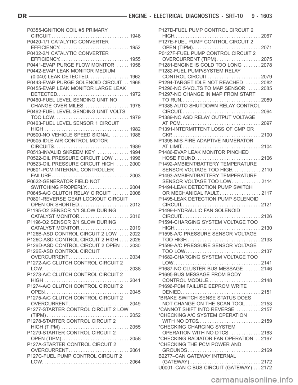
P0355-IGNITION COIL #5 PRIMARY
CIRCUIT................................. 1948
P0420-1/1 CATALYTIC CONVERTER
EFFICIENCY............................. 1952
P0432-2/1 CATALYTIC CONVERTER
EFFICIENCY............................. 1955
P0441-EVAP PURGE FLOW MONITOR . . . . . 1958
P0442-EVAP LEAK MONITOR MEDIUM
(0.040) LEAK DETECTED.................. 1962
P0443-EVAP PURGE SOLENOID CIRCUIT . . 1968
P0455-EVAP LEAK MONITOR LARGE LEAK
DETECTED............................... 1972
P0460-FUEL LEVEL SENDING UNIT NO
CHANGE OVER MILES.................... 1978
P0462-FUEL LEVEL SENDING UNIT VOLTS
TOO LOW................................ 1979
P0463-FUEL LEVEL SENSOR 1 CIRCUIT
HIGH.................................... 1982
P0500-NO VEHICLE SPEED SIGNAL ....... 1986
P0505-IDLE AIR CONTROL MOTOR
CIRCUITS................................ 1989
P0513-INVALID SKREEM KEY ............. 1994
P0522-OIL PRESSURE CIRCUIT LOW ...... 1996
P0523-OIL PRESSURE CIRCUIT HIGH ..... 2000
P0601-PCM INTERNAL CONTROLLER
FAILURE................................. 2003
P0622-GENERATOR FIELD NOT
SWITCHING PROPERLY.................. 2004
P0645-A/C CLUTCH RELAY CIRCUIT . . ..... 2008
P0801-REVERSE GEAR LOCKOUT CIRCUIT
OPEN OR SHORTED...................... 2012
P1195-O2 SENSOR 1/1 SLOW DURING
CATALYST MONITOR..................... 2016
P1196-O2 SENSOR 2/1 SLOW DURING
CATALYST MONITOR..................... 2019
P126B-ASD CONTROL CIRCUIT 2 LOW .... 2022
P126C-ASD CONTROL CIRCUIT 2 HIGH .... 2026
P126D-ASD CONTROL CIRCUIT 2 OPEN . . . 2030
P126E-ASD CONTROL CIRCUIT
OVERCURRENT.......................... 2034
P1272-A/C CLUTCH CONTROL CIRCUIT 2
LOW..................................... 2038
P1273-A/C CLUTCH CONTROL CIRCUIT 2
HIGH.................................... 2041
P1274-A/C CLUTCH CONTROL CIRCUIT 2
OPEN.................................... 2045
P1275-A/C CLUTCH CONTROL CIRCUIT 2
OVERCURRENT.......................... 2049
P1277-STARTER CONTROL CIRCUIT 2 LOW
(TIPM)................................... 2052
P1278-STARTER CONTROL CIRCUIT 2
HIGH (TIPM).............................. 2055
P1279-STARTER CONTROL CIRCUIT 2
OPEN (TIPM)............................. 2058
P127A-STARTER CONTROL CIRCUIT 2
OVERCURRENT.......................... 2061
P127C-FUEL PUMP CONTROL CIRCUIT 2
LOW..................................... 2064P127D-FUEL PUMP CONTROL CIRCUIT 2
HIGH.................................... 2067
P127E-FUEL PUMP CONTROL CIRCUIT 2
OPEN (TIPM)............................. 2071
P0127F-FUEL PUMP CONTROL CIRCUIT 2
OVERCURRENT (TIPM)................... 2075
P1281-ENGINE IS COLD TOO LONG ....... 2078
P1282-FUEL PUMP/SYSTEM RELAY
CONTROL CIRCUIT....................... 2079
P1294-TARGET IDLE NOT REACHED ...... 2082
P1296-NO 5-VOLTS TO MAP SENSOR ..... 2085
P1297-NO CHANGE IN MAP FROM START
TO RUN.................................. 2089
P1388-AUTO SHUTDOWN RELAY CONTROL
CIRCUIT................................. 2094
P1389-NO ASD RELAY OUTPUT VOLTAGE
AT P C M.................................. 2097
P1391-INTERMITTENT LOSS OF CMP OR
CKP
..................................... 2100
P1398-MIS-FIRE ADAPTIVE NUMERATOR
AT L I M I T................................. 2104
P1486-EVAP LEAK MONITOR PINCHED
HOSE FOUND............................ 2106
P1492-AMBIENT/BATTERY TEMPERATURE
SENSOR VOLTAGE TOO HIGH............. 2110
P1493-AMBIENT/BATTERY TEMPERATURE
SENSOR VOLTAGE TOO LOW............. 2114
P1494-LEAK DETECTION PUMP SWITCH
OR MECHANICAL FAULT.................. 2117
P1495-LEAK DETECTION PUMP SOLENOID
CIRCUIT................................. 2121
P1499-HYDRAULIC FAN SOLENOID
CIRCUIT................................. 2126
P1594-CHARGING SYSTEM VOLTAGE TOO
HIGH.................................... 2130
P1598-A/C PRESSURE SENSOR VOLTAGE
TOO HIGH............................... 2133
P1599-A/C PRESSURE SENSOR VOLTAGE
TOO LOW................................ 2137
P1682-CHARGING SYSTEM VOLTAGE TOO
LOW..................................... 2141
P1687-NO CLUSTER BUS MESSAGE ...... 2146
P1695-BUS MESSAGE FROM BODY
CONTROL MODULE...................... 2148
P1696-PCM FAILURE EEPROM WRITE
DENIED.................................. 2151
*BRAKE SWITCH SENSE STATUS DOES
NOT CHANGE ON THE SCAN TOOL....... 2153
*CANNOT SHIFT INTO REVERSE .......... 2157
*CHECKING A/C SYSTEM OPERATION
WITH NO DTCS.......................... 2159
*CHECKING CHARGING SYSTEM
OPERATION WITH NO DTCS.............. 2163
*CHECKING RADIATOR FAN OPERATION . . 2167
*CHECKING THE PCM POWER AND
GROUNDS............................... 2169
B2277–CAN GATEWAY INTERNAL
(GATEWAY).............................. 2172
U0001–CAN C BUS CIRCUIT (GATEWAY) . . . 2172
Page 913 of 5267

U0002–CAN C BUS PERFORMANCE
(GATEWAY).............................. 2172
U0100–LOST COMMUNICATION WITH
ECM/PCM (GATEWAY).................... 2172
U0121–LOST COMMUNICATION WITH
ANTI-LOCK BRAKE MODULE (GATEWAY). . 2172
U0155–LOST COMMUNICATION WITH
CLUSTER/CCN (GATEWAY)............... 2173U0168–LOST COMMUNICATION WITH
VEHICLE SECURITY CONTROL MODULE -
SKREEM/WCM (GATEWAY)................ 2173
STANDARD PROCEDURE
POWERTRAIN VERIFICATION TEST ....... 2174
Page 914 of 5267
ENGINE - ELECTRICAL DIAGNOSTICS - SRT-10
DIAGNOSIS AND TESTING
Page 915 of 5267
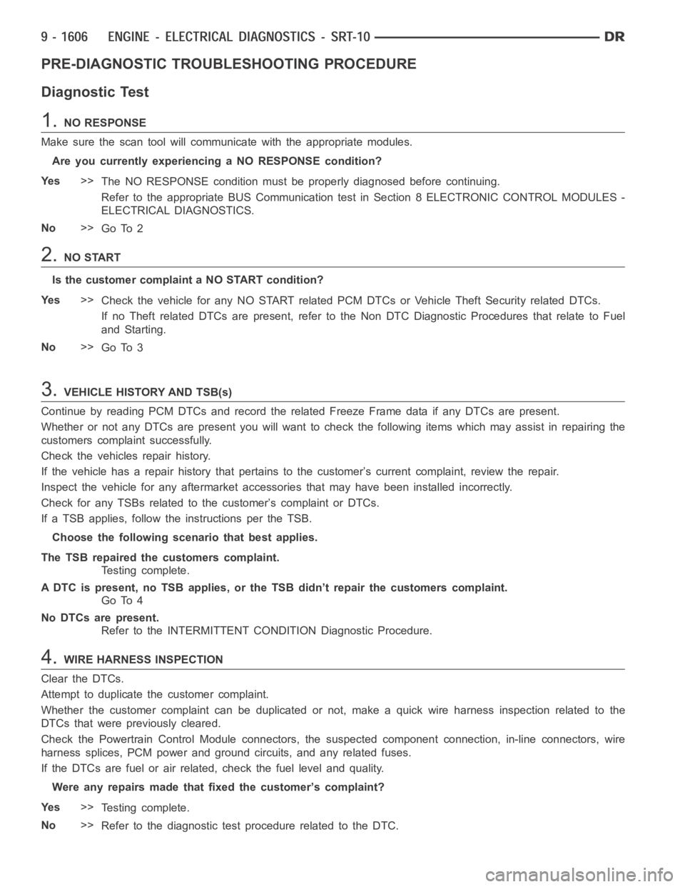
PRE-DIAGNOSTIC TROUBLESHOOTING PROCEDURE
Diagnostic Test
1.NO RESPONSE
Make sure the scan tool will communicate with the appropriate modules.
Are you currently experiencing a NO RESPONSE condition?
Ye s>>
The NO RESPONSE condition must be properly diagnosed before continuing.
Refer to the appropriate BUS Communication test in Section 8 ELECTRONIC CONTROL MODULES -
ELECTRICAL DIAGNOSTICS.
No>>
Go To 2
2.NO START
Is the customer complaint a NO START condition?
Ye s>>
Check the vehicle for any NO START related PCM DTCs or Vehicle Theft Security related DTCs.
If no Theft related DTCs are present, refer to the Non DTC Diagnostic Procedures that relate to Fuel
and Starting.
No>>
Go To 3
3.VEHICLE HISTORY AND TSB(s)
Continue by reading PCM DTCs and record the related Freeze Frame data if anyDTCs are present.
Whether or not any DTCs are present you will want to check the following items which may assist in repairing the
customers complaint successfully.
Check the vehicles repair history.
If the vehicle has a repair history that pertains to the customer’s currentcomplaint, review the repair.
Inspect the vehicle for any aftermarket accessories that may have been installed incorrectly.
Check for any TSBs related to thecustomer’s complaint or DTCs.
If a TSB applies, follow the instructions per the TSB.
Choose the following scenario that best applies.
The TSB repaired the customers complaint.
Testing complete.
A DTC is present, no TSB applies, or the TSB didn’t repair the customers complaint.
Go To 4
No DTCs are present.
Refer to the INTERMITTENT CONDITION Diagnostic Procedure.
4.WIRE HARNESS INSPECTION
Clear the DTCs.
Attempt to duplicate the customer complaint.
Whether the customer complaint can be duplicated or not, make a quick wire harness inspection related to the
DTCs that were previously cleared.
Check the Powertrain Control Module connectors, the suspected componentconnection, in-line connectors, wire
harness splices, PCM power and ground circuits, and any related fuses.
If the DTCs are fuel or air related, check the fuel level and quality.
Were any repairs made that fixed the customer’s complaint?
Ye s>>
Testing complete.
No>>
Refer to the diagnostic test procedure related to the DTC.
Page 916 of 5267
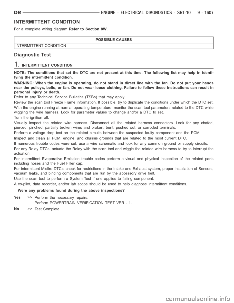
INTERMITTENT CONDITION
For a complete wiring diagramRefer to Section 8W.
POSSIBLE CAUSES
INTERMITTENT CONDITION
Diagnostic Test
1.INTERMITTENT CONDITION
NOTE: The conditions that set the DTC are not present at this time. The following list may help in identi-
fying the intermittent condition.
WARNING: When the engine is operating, do not stand in direct line with the fan. Do not put your hands
near the pulleys, belts, or fan. Do notwear loose clothing. Failure to follow these instructions can result in
personal injury or death.
Refer to any Technical Service Bulletins (TSBs) that may apply.
Review the scan tool Freeze Frame information. If possible, try to duplicate the conditions under which the DTC set.
With the engine running at normal operating temperature, monitor the scantool parameters relatedtotheDTCwhile
wiggling the wire harness. Look for parameter values to change and/or a DTCto set.
Turn the ignition off.
Visually inspect the related wire harness. Disconnect all the related harness connectors. Look for any chafed,
pierced, pinched, partially broken wires and broken, bent, pushed out, orcorroded terminals.
Perform a voltage drop test on the related circuits between the suspected faulty component and the PCM.
Inspect and clean all PCM, engine, and chassis grounds that are related to the most current DTC.
If numerous trouble codes were set, use a wire schematic and look for any common ground or supply circuits.
For any Relay DTCs, actuate the Relay with the scan tool and wiggle the related wire harness to try to interrupt the
actuation.
For intermittent Evaporative Emission trouble codes perform a visual andphysical inspection of the related parts
including hoses and the Fuel Filler cap.
For intermittent Misfire DTC’s check for restrictions in the Intake and Exhaust system, proper installation of Sensors,
vacuum leaks, and binding components that are run by the accessory drive belt.
Use the scan tool to perform a System Test if one applies to failing component.
A co-pilot, data recorder, and/or lab scope should be used to help diagnoseintermittent conditions.
Were any problems found during the above inspections?
Ye s>>
Perform the necessary repairs.
Perform POWERTRAIN VERIFICATION TEST VER - 1.
No>>
Te s t C o m p l e t e .
Page 917 of 5267
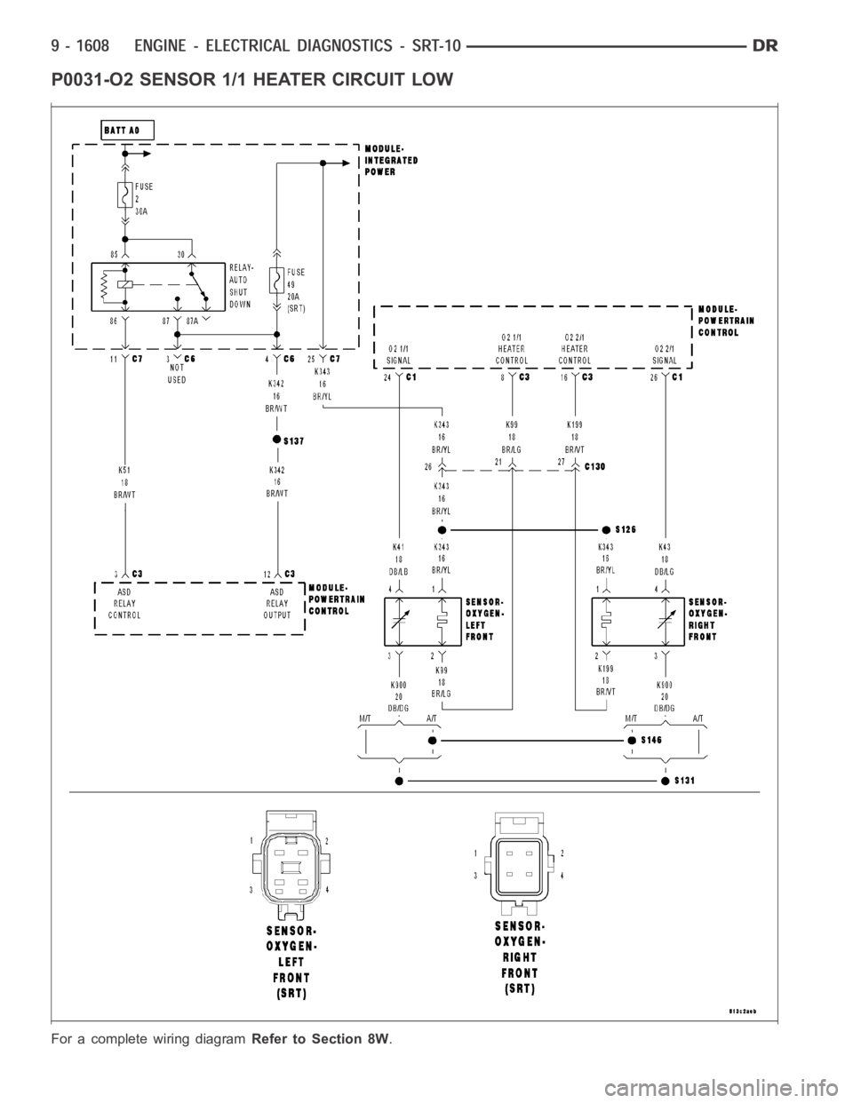
P0031-O2 SENSOR 1/1 HEATER CIRCUIT LOW
For a complete wiring diagramRefer to Section 8W.
Page 918 of 5267
When Monitored:
Battery voltage above 10.6 volts, ASD is powered up, and O2 heater is on.
Set Condition:
Desired state does not match Actual state.
Possible Causes
O2 HEATER TEST
O2 SENSOR HEATER ELEMENT
(K343) FUSED ASD RELAY OUTPUT CIRCUIT
(K99) HEATER CONTROL CIRCUIT OPEN
(K99) HEATER CONTROL CIRCUIT SHORTED TO GROUND
PCM
Always perform the Pre-Diagnostic Troubleshooting procedure before proceeding. (Refer to 9 - ENGINE -
DIAGNOSIS AND TESTING)
1.O2 HEATER TEST
Ignition on, engine not running.
With the scan tool, read DTCs and record the related Freeze Frame data.
With the scan tool, actuate the O2 Heater test.
Monitor the O2 Heater Voltage for 5 minutes.
Did the voltage drop down close to zero during the Heater test?
Ye s>>
Refer to the INTERMITTENT CONDITION Diagnostic Procedure.
Perform POWERTRAIN VERIFICATION TEST. (Refer to 9 - ENGINE - STANDARD PROCEDURE)
No>>
Go To 2
NOTE: Stop the actuation before continuing.
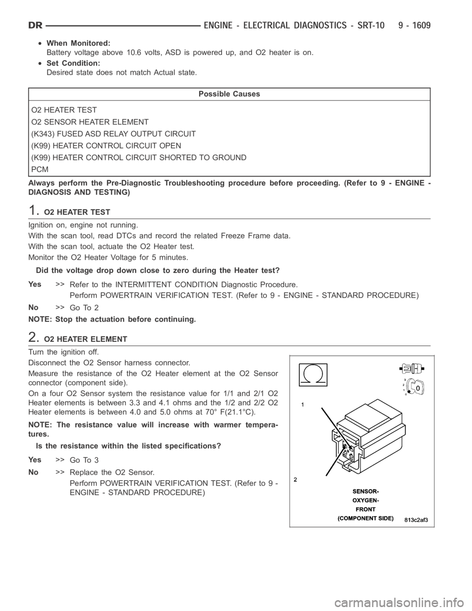
2.O2 HEATER ELEMENT
Turn the ignition off.
Disconnect the O2 Sensor harness connector.
Measure the resistance of the O2 Heater element at the O2 Sensor
connector (component side).
On a four O2 Sensor system the resistance value for 1/1 and 2/1 O2
Heater elements is between 3.3 and 4.1 ohms and the 1/2 and 2/2 O2
Heater elements is between 4.0 and 5.0 ohms at 70° F(21.1°C).
NOTE: The resistance value will increase with warmer tempera-
tures.
Is the resistance within the listed specifications?
Ye s>>
Go To 3
No>>
Replace the O2 Sensor.
Perform POWERTRAIN VERIFICATION TEST. (Refer to 9 -
ENGINE - STANDARD PROCEDURE)
Page 919 of 5267
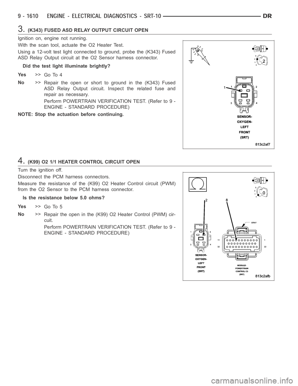
3.(K343) FUSED ASD RELAY OUTPUT CIRCUIT OPEN
Ignition on, engine not running.
With the scan tool, actuate the O2 Heater Test.
Using a 12-volt test light connected to ground, probe the (K343) Fused
ASD Relay Output circuit at the O2 Sensor harness connector.
Did the test light illuminate brightly?
Ye s>>
Go To 4
No>>
Repair the open or short to ground in the (K343) Fused
ASD Relay Output circuit. Inspect the related fuse and
repair as necessary.
Perform POWERTRAIN VERIFICATION TEST. (Refer to 9 -
ENGINE - STANDARD PROCEDURE)
NOTE: Stop the actuation before continuing.
4.(K99) O2 1/1 HEATER CONTROL CIRCUIT OPEN
Turn the ignition off.
Disconnect the PCM harness connectors.
Measure the resistance of the (K99) O2 Heater Control circuit (PWM)
from the O2 Sensor to the PCM harness connector.
Is the resistance below 5.0 ohms?
Ye s>>
Go To 5
No>>
Repair the open in the (K99) O2 Heater Control (PWM) cir-
cuit.
Perform POWERTRAIN VERIFICATION TEST. (Refer to 9 -
ENGINE - STANDARD PROCEDURE)
Page 920 of 5267
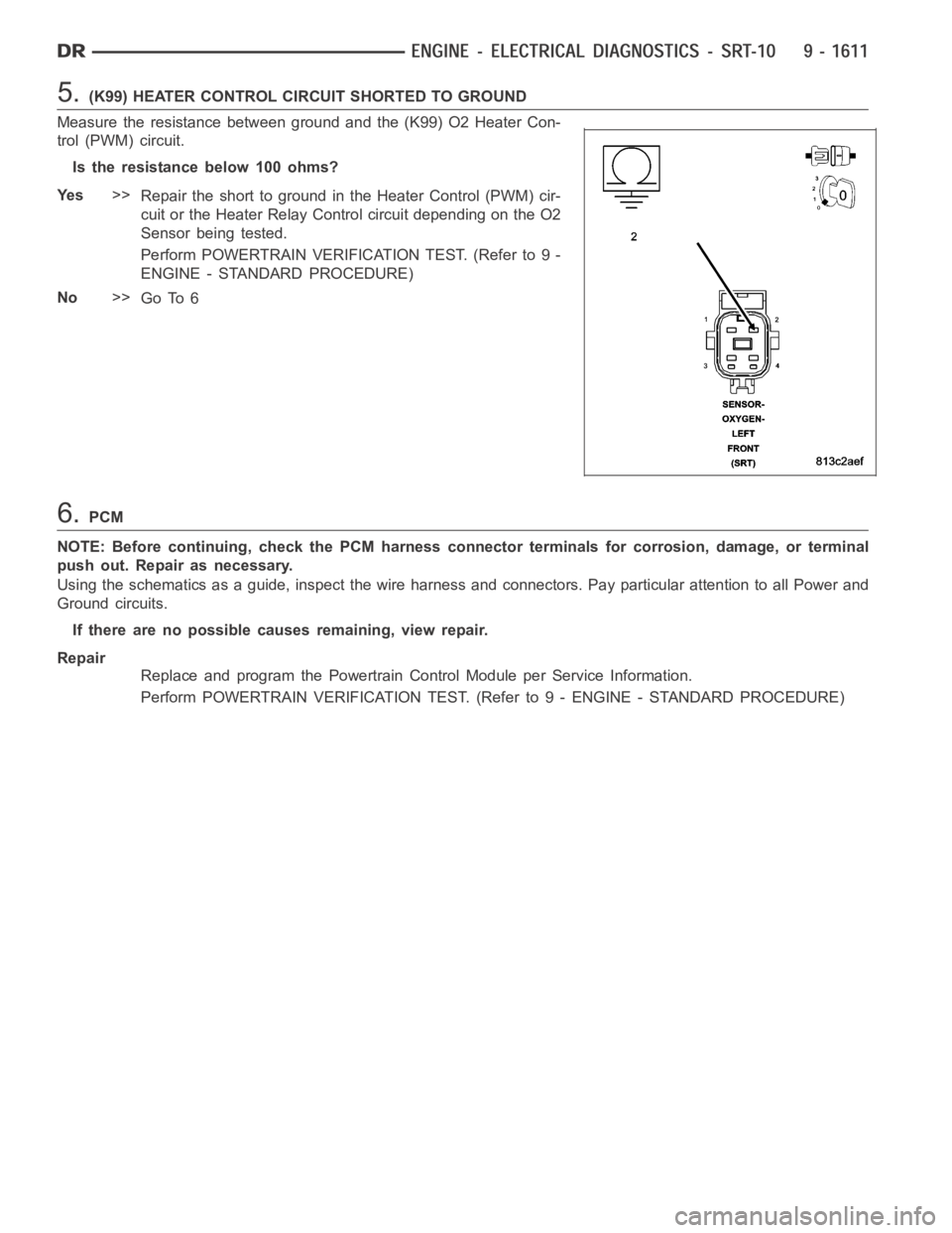
5.(K99) HEATER CONTROL CIRCUIT SHORTED TO GROUND
Measure the resistance between ground and the (K99) O2 Heater Con-
trol (PWM) circuit.
Istheresistancebelow100ohms?
Ye s>>
Repair the short to ground in the Heater Control (PWM) cir-
cuit or the Heater Relay Control circuit depending on the O2
Sensor being tested.
Perform POWERTRAIN VERIFICATION TEST. (Refer to 9 -
ENGINE - STANDARD PROCEDURE)
No>>
Go To 6
6.PCM
NOTE: Before continuing, check the PCM harness connector terminals for corrosion, damage, or terminal
push out. Repair as necessary.
Using the schematics as a guide, inspect the wire harness and connectors. Pay particular attention to all Power and
Ground circuits.
If there are no possible causes remaining, view repair.
Repair
Replace and program the Powertrain Control Module per Service Information.
Perform POWERTRAIN VERIFICATION TEST. (Refer to 9 - ENGINE - STANDARD PROCEDURE)