DODGE TRUCK 1993 Service Repair Manual
Manufacturer: DODGE, Model Year: 1993, Model line: TRUCK, Model: DODGE TRUCK 1993Pages: 1502, PDF Size: 80.97 MB
Page 1161 of 1502
21-160
TRANSMISSION OVERHAUL—32RH
• before final assembly, install cam only as de
scribed in Transmission Assembly And Adjust
ment section. Clutch cam must be properly
indexed in case to fit and operate properly.
EXTENSION
HOUSING AND PARK LOCK
COMPONENT OVERHAUL
Clean the housing and park lock components in
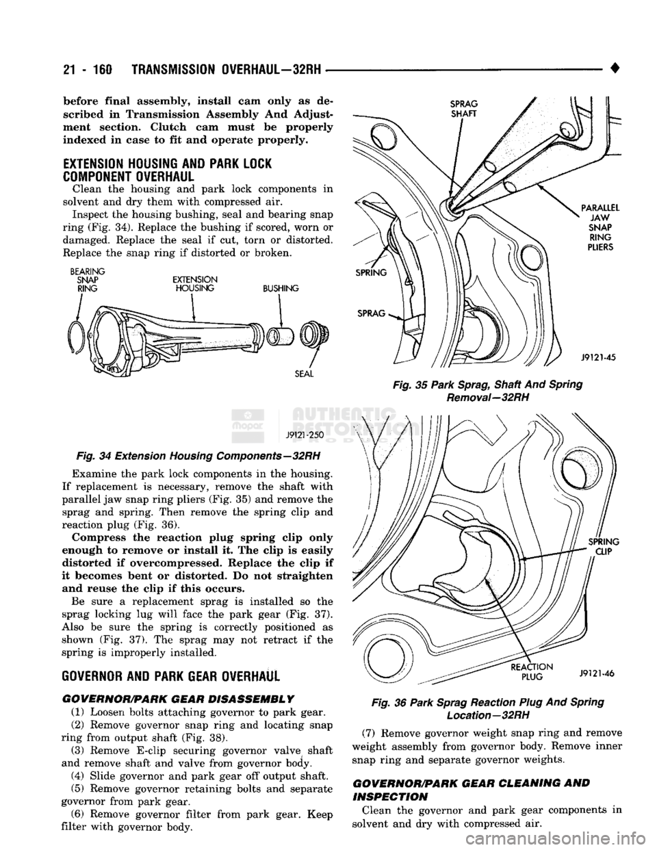
solvent and dry them with compressed air. Inspect the housing bushing, seal and bearing snap
ring (Fig. 34). Replace the bushing if scored, worn or damaged. Replace the seal if cut, torn or distorted.
Replace the snap ring if distorted or broken.
BEARING
SNAP EXTENSION RING HOUSING BUSHING
J9121-250
Fig.
34 Extension
Housing
Components—32RH
Examine the park lock components in the housing.
If replacement is necessary, remove the shaft with
parallel jaw snap ring pliers (Fig. 35) and remove the sprag and spring. Then remove the spring clip and
reaction plug (Fig. 36). Compress the reaction plug spring clip only
enough to remove or install it. The clip is easily
distorted if overcompressed. Replace the clip if
it becomes bent or distorted. Do not straighten and reuse the clip if this occurs.
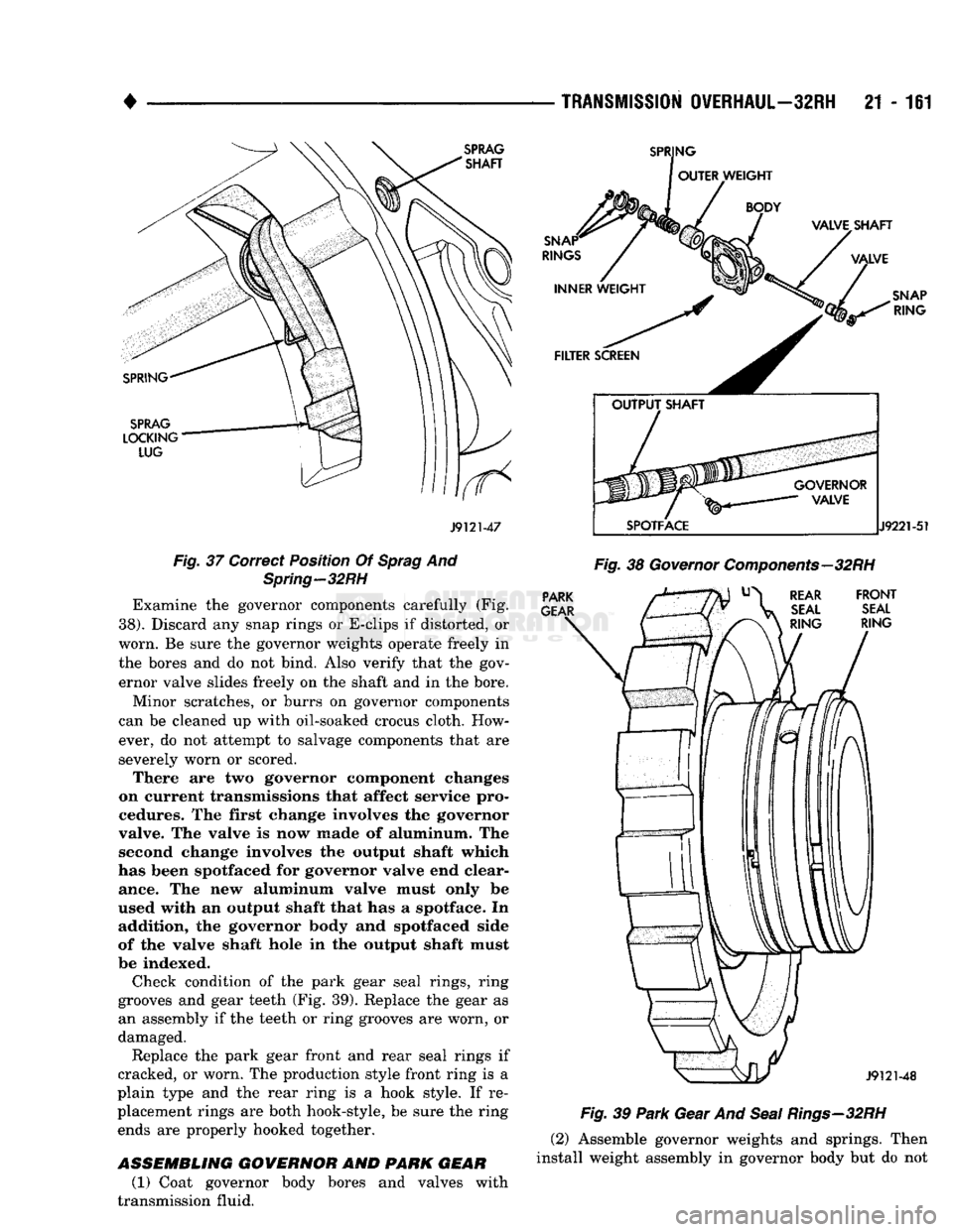
Be sure a replacement sprag is installed so the
sprag locking lug will face the park gear (Fig. 37).
Also be sure the spring is correctly positioned as shown (Fig. 37). The sprag may not retract if the
spring is improperly installed.
GOVERNOR
AND PARK GEAR OVERHAUL GOVERNOR/PARK GEAR DISASSEMBLY
(1) Loosen bolts attaching governor to park gear.
(2)
Remove governor snap ring and locating snap
ring from output shaft (Fig. 38). (3) Remove E-clip securing governor valve shaft
and remove shaft and valve from governor body.
(4) Slide governor and park gear off output shaft.
(5) Remove governor retaining bolts and separate
governor from park gear. (6) Remove governor filter from park gear. Keep
filter with governor body.
Fig.
35
Park
Sprag,
Shaft And
Spring
Removal—32RH
Fig.
36
Park
Sprag
Reaction
Plug
And
Spring
Location—32RH
(7) Remove governor weight snap ring and remove
weight assembly from governor body. Remove inner snap ring and separate governor weights.
GOVERNOR/PARK GEAR CLEANING
AND
INSPECTION
Clean the governor and park gear components in
solvent and dry with compressed air.
Page 1162 of 1502
•
J9121-47
Fig.
37 Correct Position Of
Sprag
And
Spring—32RH
Examine the governor components carefully (Fig.
38). Discard any snap rings or E-clips if distorted, or
worn. Be sure the governor weights operate freely in the bores and do not bind. Also verify that the gov
ernor valve slides freely on the shaft and in the bore.
Minor scratches, or burrs on governor components
can be cleaned up with oil-soaked crocus cloth. How ever, do not attempt to salvage components that are
severely worn or scored. There are two governor component changes
on current transmissions that affect service pro
cedures. The first change involves the governor
valve. The valve is now made of aluminum. The second change involves the output shaft which
has been spotfaced for governor valve end clear ance. The new aluminum valve must only be
used with an output shaft that has a spotface. In addition, the governor body and spotfaced side
of the valve shaft hole in the output shaft must
be indexed.
Check condition of the park gear seal rings, ring
grooves and gear teeth (Fig. 39). Replace the gear as an assembly if the teeth or ring grooves are worn, or
damaged.
Replace the park gear front and rear seal rings if
cracked, or worn. The production style front ring is a
plain type and the rear ring is a hook style. If re
placement rings are both hook-style, be sure the ring ends are properly hooked together.
ASSEMBLING
GOVERNOR
AND
PARK GEAR
(1) Coat governor body bores and valves with
transmission fluid.
TRANSMISSION
OVERHAUL—32RH
21 - 161
Fig.
39
Park
Gear And
Seal
Rings—32RH
(2) Assemble governor weights and springs. Then
install weight assembly in governor body but do not
Page 1163 of 1502
21
- 162
TRANSMISSION
OVERHAUL—32RH
• install valve and shaft at this time. These parts are
not installed until after governor and park gear are
in place on output shaft.
(3) Install new seal rings on park gear if neces
sary.
(4) Insert filter screen in park gear and install
governor body on park gear. Tighten attaching bolts
finger tight only. Bolts will not be final tightened
until after governor and park gear are mounted on
output shaft.
OIL
PUMP
AND
REACTION
SHAFT
SUPPORT
OVERHAUL
PUMP
AND
SUPPORT
DISASSEMBLY
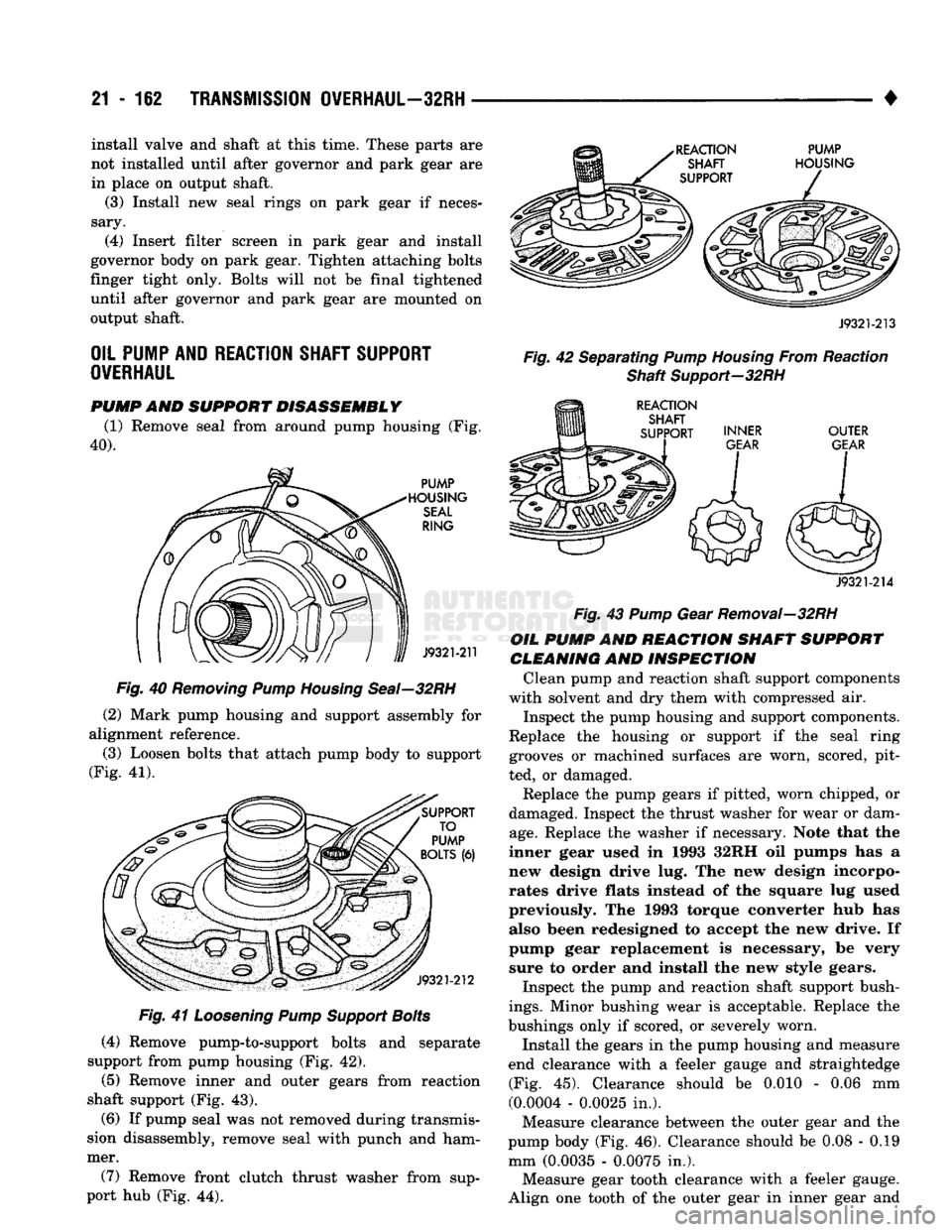
(1) Remove seal from around pump housing (Fig.
40).
Fig.
40
Removing
Pump
Housing
Seal—32RH
(2) Mark pump housing and support assembly for
alignment reference.
(3) Loosen bolts that attach pump body to support
(Fig. 41).
Fig.
41
Loosening
Pump
Support
Bolts
(4) Remove pump-to-support bolts and separate
support from pump housing (Fig. 42).
(5) Remove inner and outer gears from reaction
shaft support (Fig. 43).
(6) If pump seal was not removed during transmis
sion disassembly, remove seal with punch and ham
mer.
(7) Remove front clutch thrust washer from sup
port hub (Fig. 44).
J9321-213
Fig.
42 Separating
Pump
Housing
From Reaction
Shaft
Support-32RH
J9321-214
Fig.
43
Pump
Gear Removal—32RH
OIL
PUMP
AND
REACTION
SHAFT
SUPPORT
CLEANING
AND
INSPECTION
Clean pump and reaction shaft support components
with solvent and dry them with compressed air.
Inspect the pump housing and support components.
Replace the housing or support if the seal ring grooves or machined surfaces are worn, scored, pit
ted, or damaged.
Replace the pump gears if pitted, worn chipped, or
damaged. Inspect the thrust washer for wear or dam
age.
Replace the washer if necessary. Note that the
inner gear used in 1993 32RH oil pumps has a
new design drive lug. The new design incorpo
rates drive flats instead of the square lug used previously. The 1993 torque converter hub has also been redesigned to accept the new drive. If
pump gear replacement is necessary, be very sure to order and install the new style gears.
Inspect the pump and reaction shaft support bush
ings.
Minor bushing wear is acceptable. Replace the
bushings only if scored, or severely worn.
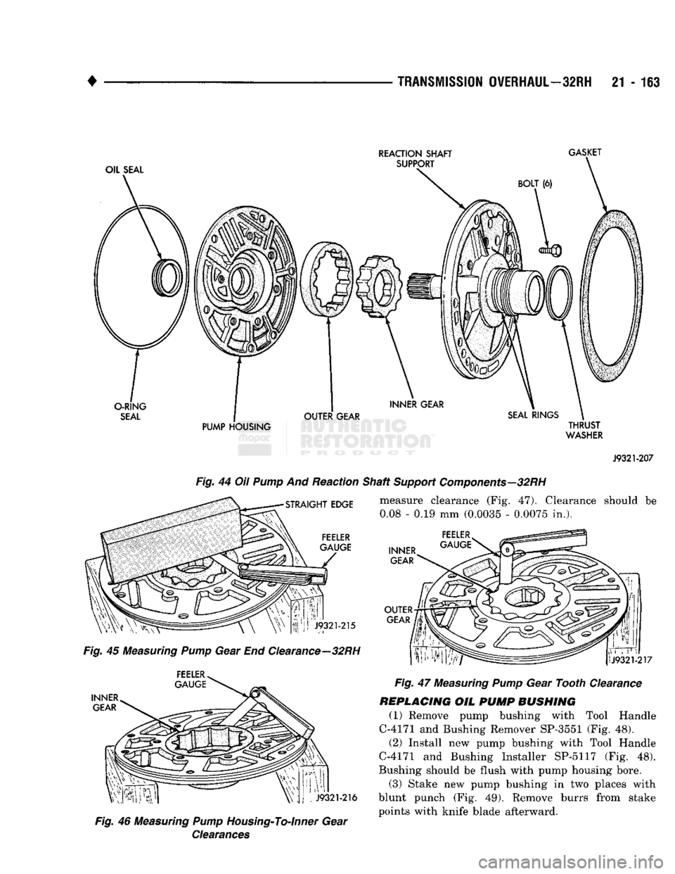
Install the gears in the pump housing and measure
end clearance with a feeler gauge and straightedge (Fig. 45). Clearance should be 0.010 - 0.06 mm
(0.0004 - 0.0025 in.).
Measure clearance between the outer gear and the
pump body (Fig. 46). Clearance should be 0.08 - 0.19
mm (0.0035 - 0.0075 in.). Measure gear tooth clearance with a feeler gauge.
Align one tooth of the outer gear in inner gear and
Page 1164 of 1502
TRANSMISSION
OVERHAUL—32RH
21 • 163
OIL SEAL REACTION SHAFT
SUPPORT GASKET
BOLT (6)
O-RING
SEAL
PUMP HOUSING THRUST
WASHER
J9321-207
Fig.
44 Oil
Pump
And Reaction Shaft
Support
Components—32RH
measure clearance (Fig. 47). Clearance should be
STRAIGHT
EDGE
FEELER
GAUGE
0.08
- 0.19 mm
(0.0035
- 0.0075 in.),
INNER
GEAR
J9321-215
Fig.
45 Measuring
Pump
Gear End Clearance—32RH FEELER
GAUGE
INNER GEAR
J9321-216
Fig.
46 Measuring
Pump
Housing-To-Inner
Gear
Clearances
OUTER
GEAR
If!
Fig.
47 Measuring
Pump
Gear Tooth Clearance
REPLACING
OIL
PUMP
BUSHING
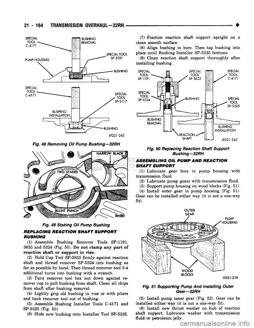
(1) Remove pump bushing with Tool Handle
C-4171 and Bushing Remover SP-3551 (Fig. 48). (2) Install new pump bushing with Tool Handle
C-4171 and Bushing Installer SP-5117 (Fig. 48).
Bushing should be flush with pump housing bore.
(3) Stake new pump bushing in two places with
blunt punch (Fig. 49). Remove burrs from stake points with knife blade afterward.
Page 1165 of 1502
21
- 164
TRANSMISSION
OVERHAUL—32RH
•
SPECIAL TOOL
C-4171
PUMP
HOUSING
BUSHING
REMOVAL
SPECIAL TOOL
C-4171
SPECIAL
TOOL
SP-3551
BUSHING
SPECIAL TOOL
SP-5117
BUSHING
J9221-242
Fig.
48
Removing
OH
Pump
Bushing—32RH
RH282
Fig.
49 Staking Oil
Pump
Bushing
REPLACING
REACTION
SHAFT
SUPPORT
BUSHING
(1) Assemble Bushing Remover Tools SP-1191,
3633 and 5324 (Fig. 50). Do not clamp any part of
reaction shaft or support in vise.
(2) Hold Cup Tool SP-3633 firmly against reaction
shaft and thread remover SP-5324 into bushing as
far as possible by hand. Then thread remover tool 3-4 additional turns into bushing with a wrench.
(3) Turn remover tool hex nut down against re
mover cup to pull bushing from shaft. Clean all chips
from shaft after bushing removal.
(4) Lightly grip old bushing in vise or with pliers
and back remover tool out of bushing.
(5) Assemble Bushing Installer Tools C-4171 and
SP-5325 (Fig. 50). (6) Slide new bushing onto Installer Tool SP-5325. (7) Position reaction shaft support upright on a
clean smooth surface. (8) Align bushing in bore. Then tap bushing into
place until Bushing Installer SP-5325 bottoms.
(9) Clean reaction shaft support thoroughly after
installing bushing.
SPECIAL
TOOL
SP-1191 SPECIAL
TOOL
C-4171
SPECIAL
_ U TQQL
SP-5325
BUSHING
INSTALLATION
J9221-243
Fig.
50 Replacing Reaction Shaft
Support
Bushing—32RH
ASSEMBLING
OIL
PUMP
AND
REACTION
SHAFT
SUPPORT
(1) Lubricate gear bore in pump housing with
transmission fluid.
(2) Lubricate pump gears with transmission fluid.
(3) Support pump housing on wood blocks (Fig. 51).
(4) Install outer gear in pump housing (Fig. 51).
Gear can be installed either way (it is not a one-way
fit).
OUTER
GEAR
PUMP
HOUSING
WOOD
BLOCKS
J9321-219
Fig.
51 Supporting
Pump
And Installing Outer
Gear-32RH
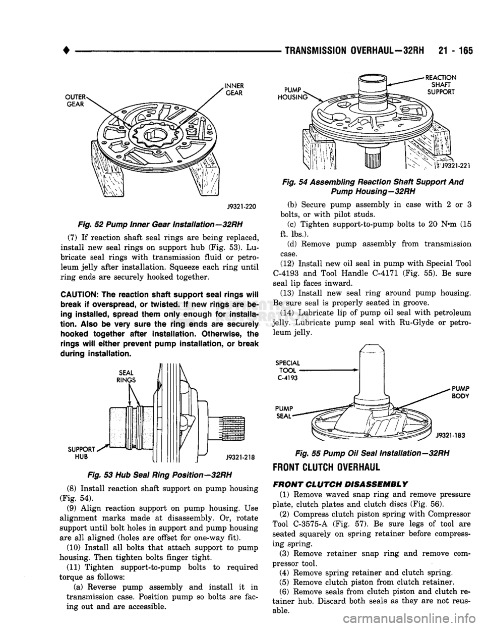
(5) Install pump inner gear (Fig. 52). Gear can be
installed either way (it is not a one-way fit). (6) Install new thrust washer on hub of reaction
shaft support. Lubricate washer with transmission
fluid or petroleum jelly.
Page 1166 of 1502
TRANSMISSION
OVERHAUL—32RH
21 - 165
OUTER
GEAR
INNER
GEAR
PUMP
HOUSING'
REACTION
SHAFT
SUPPORT
J9321-220
Fig.
52
Pump
Inner
Gear Installation—32RH
(7) If reaction shaft seal rings are being replaced,
install new seal rings on support hub (Fig. 53). Lu
bricate seal rings with transmission fluid or petro leum jelly after installation. Squeeze each ring until
ring ends are securely hooked together.
CAUTION:
The
reaction shaft support seal
rings
will
break
if
overspread,
or
twisted.
If new
rings
are be
ing installed, spread them only enough
for
installa
tion.
Also
be
very sure
the
ring ends
are
securely hooked together
after
installation. Otherwise,
the
rings
will
either
prevent pump installation,
or
break
during installation.
SEAL
RINGS SUPPORT
S*^
HUB
J9321-218
Fig.
53 Hub
Seal
Ring
Position—32RH
(8) Install reaction shaft support on pump housing
(Fig. 54).
(9) Align reaction support on pump housing. Use
alignment marks made at disassembly. Or, rotate
support until bolt holes in support and pump housing
are all aligned (holes are offset for one-way fit).
(10) Install all bolts that attach support to pump
housing. Then tighten bolts finger tight.
(11) Tighten support-to-pump bolts to required
torque as follows:
(a) Reverse pump assembly and install it in
transmission case. Position pump so bolts are fac ing out and are accessible.
|lrJ9321-221
Fig.
54
Assembling
Reaction Shaft
Support
And
Pump
Housing—32RH
(b) Secure pump assembly in case with 2 or 3
bolts,
or with pilot studs. (c) Tighten support-to-pump bolts to 20 N»m (15
ft. lbs.).
(d) Remove pump assembly from transmission
case.
(12) Install new oil seal in pump with Special Tool
C-4193 and Tool Handle C-4171 (Fig. 55). Be sure
seal lip faces inward.
(13) Install new seal ring around pump housing.
Be sure seal is properly seated in groove.
(14) Lubricate lip of pump oil seal with petroleum
jelly. Lubricate pump seal with Ru-Glyde or petro leum jelly.
SPECIAL
TOOL
C-4193
PUMP
BODY
PUMP
SEAL
LCC.
,^77/OS
J9321-183
Fig.
55
Pump
Oil
Seal
Installation-32RH
FRONT CLUTCH OVERHAUL
FRONT
CLUTCH
DISASSEMBLY
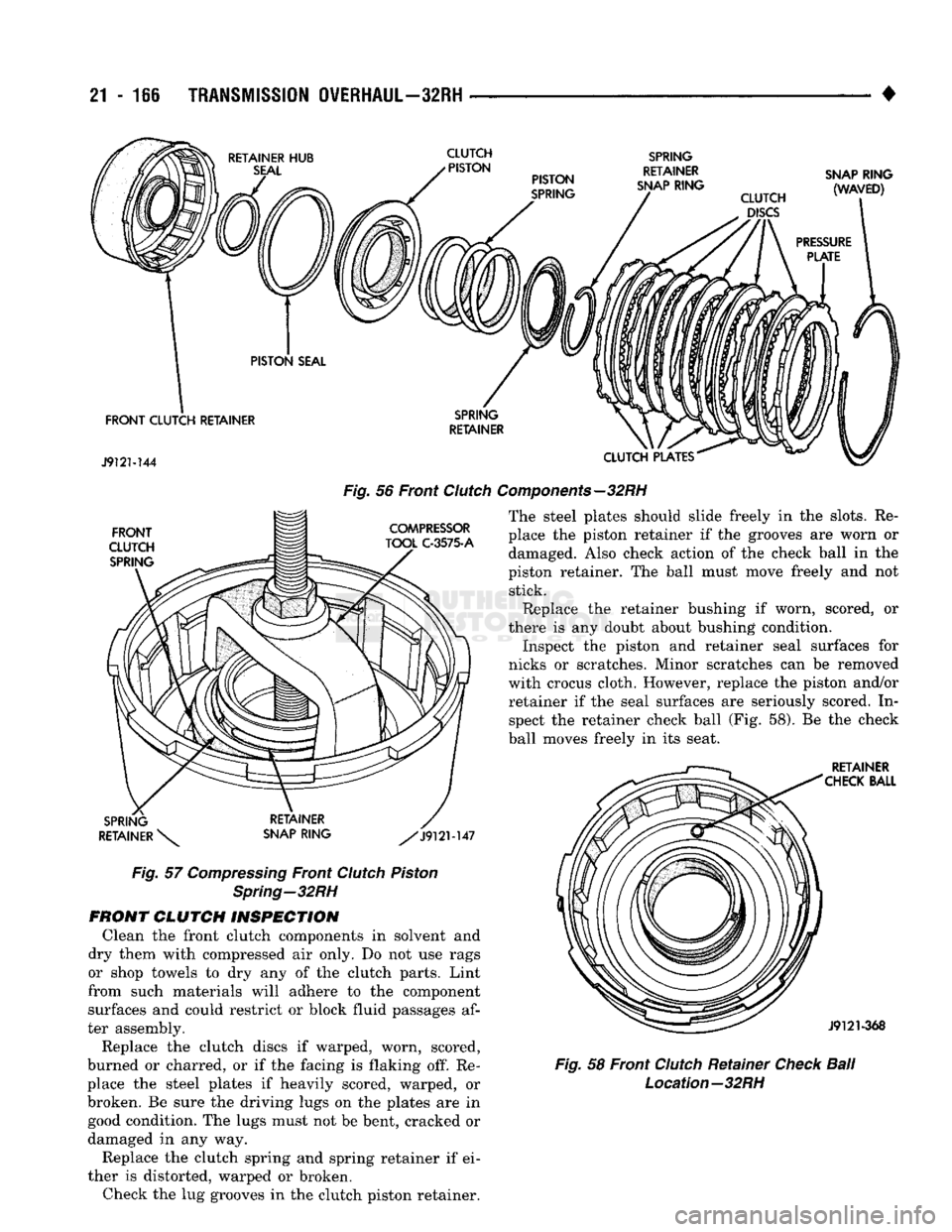
(1) Remove waved snap ring and remove pressure
plate, clutch plates and clutch discs (Fig. 56).
(2) Compress clutch piston spring with Compressor
Tool C-3575-A (Fig. 57). Be sure legs of tool are seated squarely on spring retainer before compress
ing spring.
(3) Remove retainer snap ring and remove com
pressor tool. (4) Remove spring retainer and clutch spring.
(5) Remove clutch piston from clutch retainer.
(6) Remove seals from clutch piston and clutch re
tainer hub. Discard both seals as they are not reus
able.
Page 1167 of 1502
21
- 116
TRANSMISSION
OVERHAUL—32RH
CLUTCH
>
PISTON SPRING
RETAINER
SNAP RING SNAP RING
(WAVED)
FRONT CLUTCH RETAINER
J9121-144
CLUTCH PLATES
Fig.
56 Front
Clutch
Components—32RH
FRONT
CLUTCH SPRING COMPRESSOR
TOOL C-3575-A The steel plates should slide freely in the slots. Re
place the piston retainer if the grooves are worn or damaged. Also check action of the check ball in the
piston retainer. The ball must move freely and not stick.
Replace the retainer bushing if worn, scored, or
there is any doubt about bushing condition. Inspect the piston and retainer seal surfaces for
nicks or scratches. Minor scratches can be removed
with crocus cloth. However, replace the piston and/or retainer if the seal surfaces are seriously scored. Inspect the retainer check ball (Fig. 58). Be the check
ball moves freely in its seat. RETAINER
CHECK BALL
SPRING
RETAINER \^ RETAINER
SNAP RING ^/J912M47
Fig.
57
Compressing
Front
Clutch
Piston
Spring—32RH
FRONT CLUTCH INSPECTION
Clean the front clutch components in solvent and
dry them with compressed air only. Do not use rags
or shop towels to dry any of the clutch parts. Lint
from such materials will adhere to the component surfaces and could restrict or block fluid passages af
ter assembly.
Replace the clutch discs if warped, worn, scored,
burned or charred, or if the facing is flaking off. Re
place the steel plates if heavily scored, warped, or
broken. Be sure the driving lugs on the plates are in good condition. The lugs must not be bent, cracked or
damaged in any way.
Replace the clutch spring and spring retainer if ei
ther is distorted, warped or broken. Check the lug grooves in the clutch piston retainer.
J9121-368
Fig.
58 Front
Clutch
Retainer
Check
Ball
Location—32RH
Page 1168 of 1502
TRANSMISSION
OVERHAUL—32RH
21 - 167
REPLACING
FRONT
CLUTCH RETAINER
BUSHING
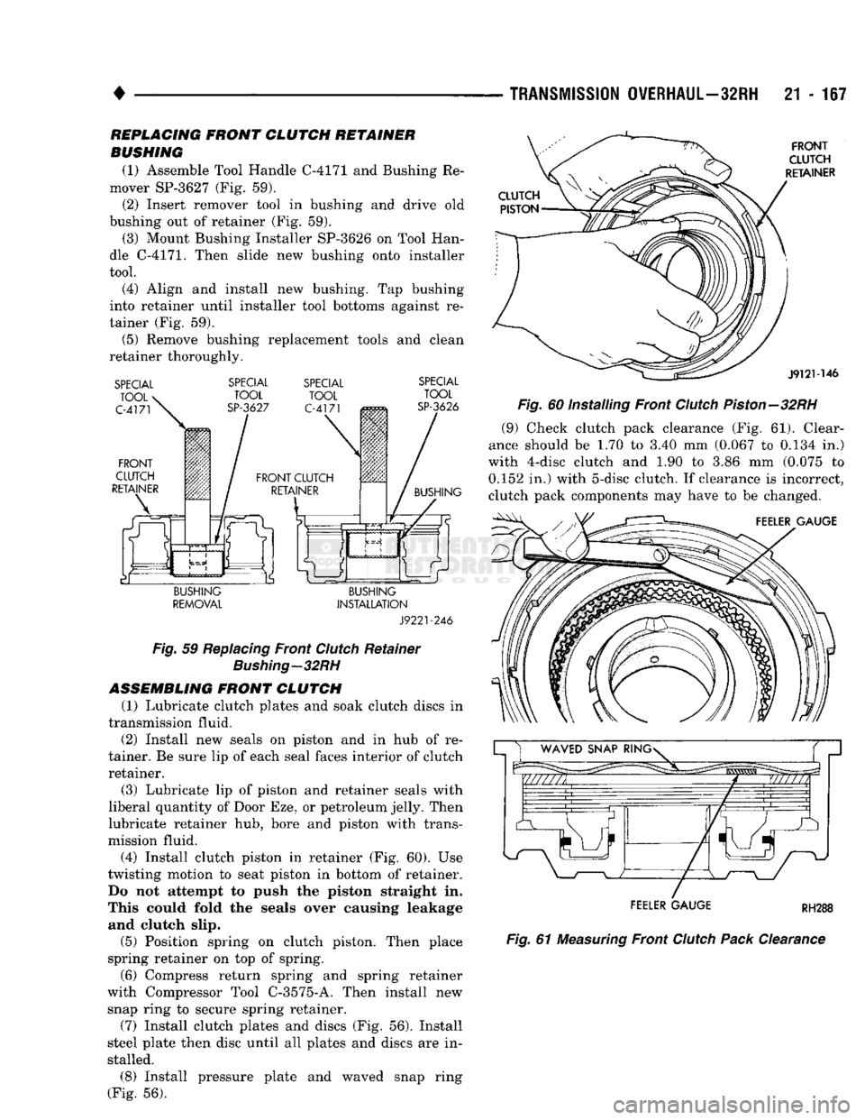
(1) Assemble Tool Handle C-4171 and Bushing Re
mover SP-3627 (Fig. 59).
(2) Insert remover tool in bushing and drive old
bushing out of retainer (Fig. 59). (3) Mount Bushing Installer SP-3626 on Tool Han
dle C-4171. Then slide new bushing onto installer
tool. (4) Align and install new bushing. Tap bushing
into retainer until installer tool bottoms against re
tainer (Fig. 59). (5) Remove bushing replacement tools and clean
retainer thoroughly.
SPECIAL
TOOL
C-4171
FRONT
CLUTCH
RETAINER
SPECIAL
TOOL
SP-3627 SPECIAL
TOOL
C-4171
SPECIAL
TOOL
SP-3626
BUSHING
BUSHING
REMOVAL
BUSHING
INSTALLATION
J9221-246
Fig.
59
Replacing
Front
Clutch
Retainer
Bushing—32RH
ASSEMBLING
FRONT CLUTCH
(1) Lubricate clutch plates and soak clutch discs in
transmission fluid. (2) Install new seals on piston and in hub of re
tainer. Be sure lip of each seal faces interior of clutch retainer.
(3) Lubricate lip of piston and retainer seals with
liberal quantity of Door Eze, or petroleum jelly. Then
lubricate retainer hub, bore and piston with trans
mission fluid.
(4) Install clutch piston in retainer (Fig. 60). Use
twisting motion to seat piston in bottom of retainer. Do not attempt to push the piston straight in.
This could fold the seals over causing leakage and clutch slip.
(5) Position spring on clutch piston. Then place
spring retainer on top of spring.
(6) Compress return spring and spring retainer
with Compressor Tool C-3575-A. Then install new snap ring to secure spring retainer.
(7) Install clutch plates and discs (Fig. 56). Install
steel plate then disc until all plates and discs are in
stalled.
(8) Install pressure plate and waved snap ring
(Fig. 56).
FRONT
CLUTCH
RETAINER
J9121-146
Fig.
60 Installing Front
Clutch
Piston—32RH
(9) Check clutch pack clearance (Fig. 61). Clear
ance should be 1.70 to 3.40 mm (0.067 to 0.134 in.)
with 4-disc clutch and 1.90 to 3.86 mm (0.075 to 0.152 in.) with 5-disc clutch. If clearance is incorrect,
clutch pack components may have to be changed.
FEELER GAUGE
FEELER GAUGE
RH288
Fig.
61
Measuring
Front
Clutch
Pack
Clearance
Page 1169 of 1502
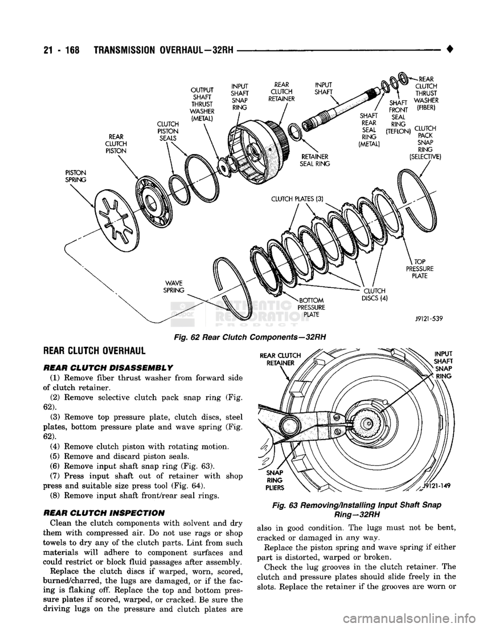
21-168
TRANSMISSION
OVERHAUL—32RH
REAR
CLUTCH PISTON CLUTCH
PISTON
SEALS
OUTPUT
SHAFT
THRUST
WASHER
(METAL) INPUT
SHAFT
SNAP
RING
REAR
CLUTCH
RETAINER INPUT
SHAFT
-REAR
CLUTCH
.
THRUST
" /
SHAFT WASHER
/
FRONT
('I"")
SHAFT SEAL
REAR
RING
rniTru
SEAL
(TEFLON)
C^TCH
RING PACK
SNAP
RING
(SELECTIVE)
PISTON
SPRING
BOTTOM
PRESSURE
PLATE CLUTCH
DISCS
(4)
TOP
PRESSURE
PLATE
J9121-539
Fig.
62 Rear
Clutcl
REAR
CLUTCH OVERHAUL
REAR
CLUTCH DISASSEMBLY
(1) Remove fiber thrust washer from forward side
of clutch retainer. (2) Remove selective clutch pack snap ring (Fig.
62).
(3) Remove top pressure plate, clutch discs, steel
plates,
bottom pressure plate and wave spring (Fig.
62).
(4) Remove clutch piston with rotating motion.
(5) Remove and discard piston seals.
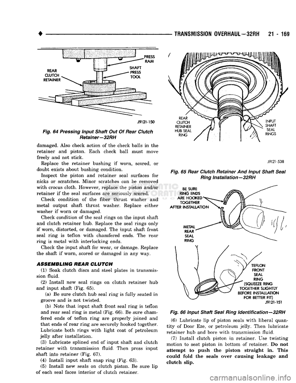
(6) Remove input shaft snap ring (Fig. 63). (7) Press input shaft out of retainer with shop
press and suitable size press tool (Fig. 64).
(8) Remove input shaft front/rear seal rings.
REAR
CLUTCH INSPECTION
Clean the clutch components with solvent and dry
them with compressed air. Do not use rags or shop
towels to dry any of the clutch parts. Lint from such materials will adhere to component surfaces and
could restrict or block fluid passages after assembly.
Replace the clutch discs if warped, worn, scored,
burned/charred, the lugs are damaged, or if the fac ing is flaking off. Replace the top and bottom pressure plates if scored, warped, or cracked. Be sure the
driving lugs on the pressure and clutch plates are
Components—32
RH
Fig.
63 Removing/Installing Input Shaft
Snap
Ring-32RH
also in good condition. The lugs must not be bent,
cracked or damaged in any way. Replace the piston spring and wave spring if either
part is distorted, warped or broken. Check the lug grooves in the clutch retainer. The
clutch and pressure plates should slide freely in the
slots.
Replace the retainer if the grooves are worn or
Page 1170 of 1502
•
TRANSMISSION
OVERHAUL—32RH
21 - 111
J9121-150
Fig. 64 Pressing input Shaft Out Of Rear Clutch Retainer—32RH damaged. Also check action of the check balls in the
retainer and piston. Each check ball must move
freely and not stick.
Replace the retainer bushing if worn, scored, or
doubt exists about bushing condition.
Inspect the piston and retainer seal surfaces for
nicks or scratches. Minor scratches can be removed
with crocus cloth. However, replace the piston and/or
retainer if the seal surfaces are seriously scored.
Check condition of the fiber thrust washer and
metal output shaft thrust washer. Replace either
washer if worn or damaged.
Check condition of the seal rings on the input shaft
and clutch retainer hub. Replace the seal rings only
if worn, distorted, or damaged. The input shaft front seal ring is teflon with chamfered ends. The rear
ring is metal with interlocking ends.
Check the input shaft for wear, or damage. Replace
the shaft if worn, scored or damaged in any way.
ASSEMBLING REAR
CLUTCH
(1) Soak clutch discs and steel plates in transmis
sion fluid.
(2)
Install new seal rings on clutch retainer hub
and input shaft (Fig. 65).
(a) Be sure clutch hub seal ring is fully seated in
groove and is not twisted.
(b) Note that input shaft front seal ring is teflon
and rear seal ring is metal (Fig. 66). Be sure cham
fered ends of teflon ring are properly joined and
that ends of rear ring are securely hooked together. Lubricate both rings with light coat of petroleum
jelly after installation.
(3) Lubricate splined end of input shaft and clutch
retainer with transmission fluid. Then press input shaft into retainer (Fig. 67).
(4)
Install input shaft snap ring (Fig. 63).
(5) Install new seals on clutch piston. Be sure lip
of each seal faces interior of clutch retainer.
J9121
-538
Fig.
65 Rear Clutch Retainer And input Shaft
Seal Ring
Installation—32RH
J912M51 Fig. 66 input Shaft Seal
Ring
Identification—32RH
(6) Lubricate lip of piston seals with liberal quan
tity of Door Eze, or petroleum jelly. Then lubricate
retainer hub and bore with transmission fluid. (7) Install clutch piston in retainer. Use twisting
motion to seat piston in bottom of retainer. Do not attempt to push the piston straight in. This
could fold the seals over causing leakage and
clutch slip.