DODGE TRUCK 1993 Service Repair Manual
Manufacturer: DODGE, Model Year: 1993, Model line: TRUCK, Model: DODGE TRUCK 1993Pages: 1502, PDF Size: 80.97 MB
Page 361 of 1502
8D
- 10
IGNITION
SYSTEMS
• Arcing at the tower will carbonize the cable boot,
which if it is connected to a new ignition coil, will cause the coil to fail. If the secondary coil cable shows any signs of dam
age,
it should be replaced with a new cable and new
terminal. Carbon tracking on the old cable can cause
arcing and the failure of a new ignition coil.
ENGINE
COOLANT
TEMPERATURE
SENSOR
TEST
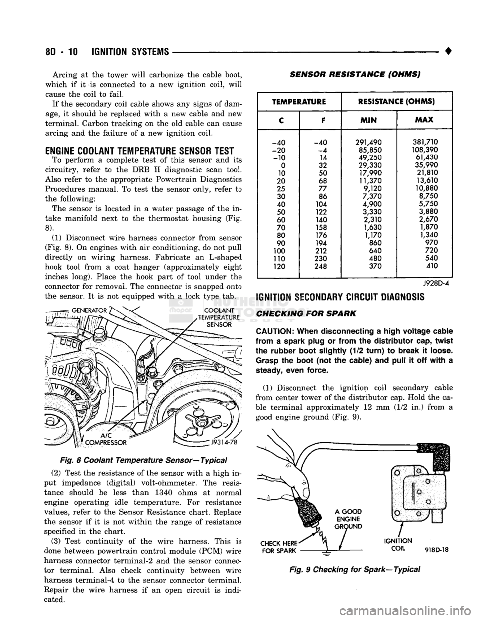
To perform a complete test of this sensor and its
circuitry, refer to the DRB II diagnostic scan tool.
Also refer to the appropriate Powertrain Diagnostics
Procedures manual. To test the sensor only, refer to
the following: The sensor is located in a water passage of the in
take manifold next to the thermostat housing (Fig.
8).
(1) Disconnect wire harness connector from sensor
(Fig. 8). On engines with air conditioning, do not pull
directly on wiring harness. Fabricate an L-shaped
hook tool from a coat hanger (approximately eight inches long). Place the hook part of tool under the
connector for removal. The connector is snapped onto
the sensor. It is not equipped with a lock type tab.
COOLANT
TEMPERATURE
SENSOR
SENSOR RESISTANCE (OHMSJ
V
J9314-78
Fig. 8 Coolant Temperature Sensor—Typical (2) Test the resistance of the sensor with a high in
put impedance (digital) volt-ohmmeter. The resis tance should be less than 1340 ohms at normal
engine operating idle temperature. For resistance
values, refer to the Sensor Resistance chart. Replace
the sensor if it is not within the range of resistance specified in the chart.
(3) Test continuity of the wire harness. This is
done between powertrain control module (PCM) wire
harness connector terminal-2 and the sensor connec
tor terminal. Also check continuity between wire harness terminal-4 to the sensor connector terminal. Repair the wire harness if an open circuit is indi
cated.
TEMPERATURE
RESISTANCE
(OHMS)
C
F
MIN
MAX
-40 -40 291,490 381,710
-20
-4
85,850
108,390
-10 14
49,250 61,430
0
32 29,330
35,990
10 50 17,990 21,810
20 68 11,370 13,610
25
77 9,120 10,880
30 86
7,370
8,750
40 104
4,900
5,750
50 122
3,330 3,880
60 140 2,310
2,670
70 158
1,630 1,870
80 176
1,170 1,340
90 194
860
970
100 212 640
720
110 230 480 540
120 248 370 410
J928D-4
IGNITION
SECONDARY
CIRCUIT
DIAGNOSIS
CHECKING FOR SPARK
CAUTION:
When
disconnecting a
high
voltage
cable
from
a spark
plug
or
from
the
distributor
cap,
twist
the rubber
boot
slightly
(1/2
turn)
to
break
it
loose.
Grasp
the
boot
(not the cable) and
pull
it off
with
a
steady,
even force.
(1) Disconnect the ignition coil secondary cable
from center tower of the distributor cap. Hold the ca
ble terminal approximately 12 mm (1/2 in.) from a good engine ground (Fig. 9).
CHECK
HERE
FOR
SPARK
IGNITION
COIL
918D-18
Fig. 9 Checking for Spark—Typical
Page 362 of 1502
*
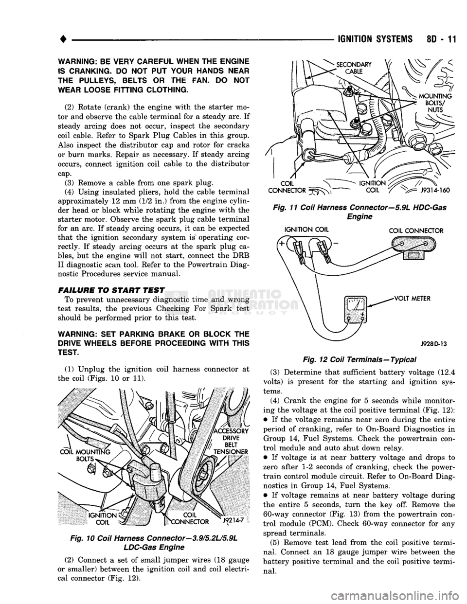
(1) Unplug the ignition coil harness connector at
the coil (Figs. 10 or 11).
Fig.
10
Coil
Harness
Connector—3.9/5.2L/5.9L
LDC-Gas
Engine
(2) Connect a set of small jumper wires (18 gauge
or smaller) between the ignition coil and coil electri
cal connector (Fig. 12).
IGNITION
SYSTEMS
80 - 11
Fig.
11
Coil
Harness
Connector—5.9L
HDC-Gas
Engine
IGNITION
COIL COIL CONNECTOR
J928D-13
Fig.
12
Coil
Terminals—Typical (3) Determine that sufficient battery voltage (12.4
volts) is present for the starting and ignition sys
tems.
(4) Crank the engine for 5 seconds while monitor
ing the voltage at the coil positive terminal (Fig. 12):
• If the voltage remains near zero during the entire
period of cranking, refer to On-Board Diagnostics in Group 14, Fuel Systems. Check the powertrain con
trol module and auto shut down relay.
• If voltage is at near battery voltage and drops to
zero after 1-2 seconds of cranking, check the power-
train control module circuit. Refer to On-Board Diag nostics in Group 14, Fuel Systems.
• If voltage remains at near battery voltage during
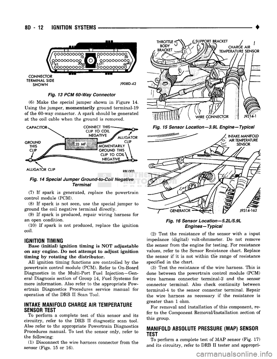
the entire 5 seconds, turn the key off. Remove the 60-way connector (Fig. 13) from the powertrain con
trol module (PCM). Check 60-way connector for any spread terminals.
(5) Remove test lead from the coil positive termi
nal.
Connect an 18 gauge jumper wire between the
battery positive terminal and the coil positive termi
nal.
WARNING: BE VERY CAREFUL WHEN THE ENGINE
IS
CRANKING.
DO NOT PUT
YOUR HANDS NEAR
THE PULLEYS, BELTS
OR THE FAN. DO NOT
WEAR LOOSE
FITTING
CLOTHING.
(2) Rotate (crank) the engine with the starter mo
tor and observe the cable terminal for a steady arc. If steady arcing does not occur, inspect the secondary
coil cable. Refer to Spark Plug Cables in this group.
Also inspect the distributor cap and rotor for cracks
or burn marks. Repair as necessary. If steady arcing occurs, connect ignition coil cable to the distributor
cap.
(3) Remove a cable from one spark plug.
(4) Using insulated pliers, hold the cable terminal
approximately 12 mm (1/2 in.) from the engine cylin
der head or block while rotating the engine with the starter motor. Observe the spark plug cable terminal
for an arc. If steady arcing occurs, it can be expected
that the ignition secondary system is" operating cor rectly. If steady arcing occurs at the spark plug ca
bles,
but the engine will not start, connect the DRB II diagnostic scan tool. Refer to the Powertrain Diag
nostic Procedures service manual.
FAILURE
TO START TEST To prevent unnecessary diagnostic time and wrong
test results, the previous Checking For Spark test should be performed prior to this test.
WARNING: SET PARKING BRAKE
OR
BLOCK
THE
DRIVE WHEELS BEFORE PROCEEDING
WITH
THIS
TEST.
Page 363 of 1502
8D
- 12
IGNITION
SYSTEMS
•
XX
oooooooooo
,0000000000
\2141
3%
lOOOOOOOOOO
OOOOOOOOOO
si
20
fcji^OQOOOOOOJ
«r
~
• • -
•
- - #
•oooooooooo.
CONNECTOR
TERMINAL
SIDE
SHOWN
J908D-42
Fig. 13 PCM 60-Way Connector
(6) Make the special jumper shown in Figure 14.
Using the jumper, momentarily ground terminal-19
of the 60-way connector. A spark should be generated at the coil cable when the ground is removed.
CAPACITOR
GROUND
THIS
CLIP
CONNECT
THIS-
ALLIGATOR
CLIP
MOMENTARILY
GROUND
THIS
CLIP
TO
COIL^
NEGATIVE
ALLIGATOR
CLIP
PR1003
Fig. 14 Special Jumper Ground-to-Coil Negative Terminal (7) If spark is generated, replace the powertrain
control module (PCM).
(8) If spark is not seen, use the special jumper to
ground the coil negative terminal directly. (9) If spark is produced, repair wiring harness for
an open condition. (10) If spark is not produced, replace the ignition
coil.
IGNITION TIMING
Base (Initial) ignition timing Is NOT adjustable
on any engine. Do not attempt to adjust Ignition
timing by rotating the distributor. All ignition timing functions are controlled by the
powertrain control module (PCM). Refer to On-Board Diagnostics in the Multi-Port Fuel Injection—Gen
eral Diagnosis section of Group 14, Fuel Systems for
more information. Also refer to the appropriate Pow ertrain Diagnostics Procedures service manual for
operation of the DRB II Scan Tool.
INTAKE
MANIFOLD
CHARGE
AIR
TEMPERATURE
SENSOR
TEST
To perform a complete test of this sensor and its
circuitry, refer to the DRB II diagnostic scan tool.
Also refer to the appropriate Powertrain Diagnostics Procedures manual. To test the sensor only, refer to
the following: (1) Disconnect the wire harness connector from the
sensor (Figs. 15 or 16).
THROTTLE
^
BODY
^
BRACKET
SUPPORT BRACKET
/
CHARGE
AIR
TEMPERATURE
SENSOR
Fig. 15 Sensor Location--3.9L Engine—Typical
INTAKE
MANIFOLD
AIR
TEMPERATURE
W
SENSOR
J9314-162
Fig. 16
Sensor
Location—5.2U5.9L
Engines—Typical
(2) Test the resistance of the sensor with a input
impedance (digital) volt-ohmmeter. Do not remove
the sensor from the engine for testing. For resistance
values, refer to the Sensor Resistance chart. Replace
the sensor if it is not within the range of resistance specified in the chart.
(3) Test the resistance of the wire harness. This is
done between the powertrain control module (PCM)
wire harness connector terminal-2 and the sensor connector terminal. Also check continuity between
terminal-4 to the sensor connector terminal. Repair
the wire harness as necessary if the resistance is greater than 1 ohm.
For removal and installation of this component, re
fer to the Component Removal/Installation section of
this group.
MANIFOLD
ABSOLUTE PRESSURE
(MAP)
SENSOR
TEST
To perform a complete test of MAP sensor (Fig. 17)
and its circuitry, refer to DRB II tester and appropri-
Page 364 of 1502
IGNITION
SYSTEMS
8D - 13
SENSOR RESISTANCE (OHMS)
TEMPERATURE
RESISTANCE
(OHMS)
C
F
MIN
MAX
-40 -40 291,490 381,710
-20
-4
85,850 108,390
-10 14 49,250 61,430
0
32 29,330
35,990
10 50 17,990 21,810
20 68 11,370
13,610
25
77 9,120
10,880
30 86
7,370
8,750
40 104
4,900
5,750
50 122
3,330
3,880
60 140 2,310
2,670
70 158
1,630
1,870
80 176
1,170
1,340
90 194 860
970
100 212 640
720
110 230 480
540
120 248 370
410
J928D-4
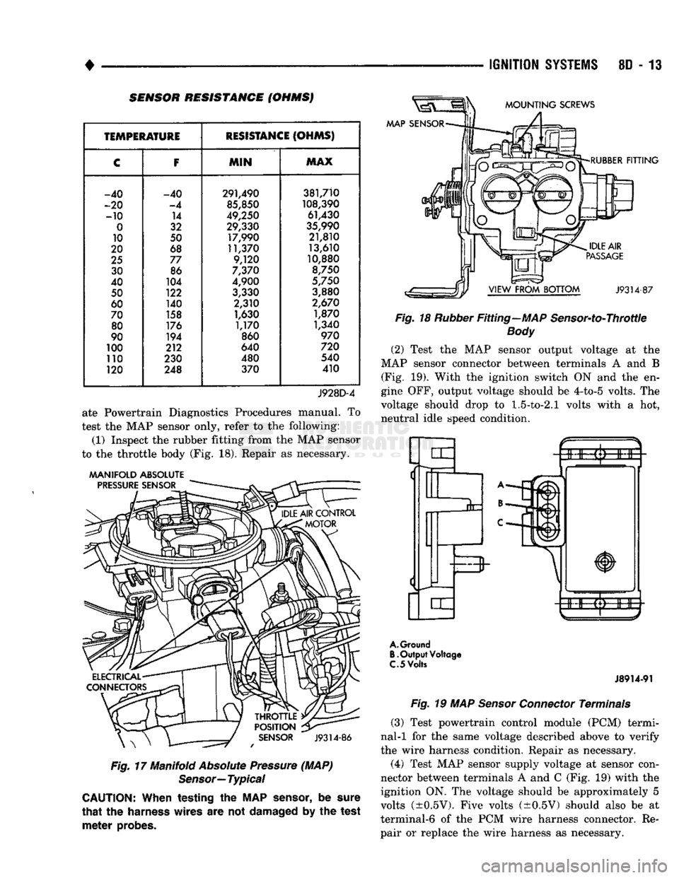
ate Powertrain Diagnostics Procedures manual. To
test the MAP sensor only, refer to the following:
(1) Inspect the rubber fitting from the MAP sensor
to the throttle body (Fig. 18). Repair as necessary.
MANIFOLD
ABSOLUTE
PRESSURE
SENSOR
J9314-86
Fig.
17 Manifold
Absolute
Pressure
(MAP)
Sensor—
Typical
CAUTION:
When
testing
the MAP
sensor,
be
sure
that
the
harness
wires
are not damaged by the
test
meter
probes.
AAAP
SENSOR
MOUNTING
SCREWS
RUBBER
FITTING
J9314-87
Fig.
18
Rubber
Fitting—MAP Sensor-to-Throttle
Body
(2) Test the MAP sensor output voltage at the
MAP sensor connector between terminals A and B (Fig. 19). With the ignition switch ON and the en
gine OFF, output voltage should be 4-to-5 volts. The
voltage should drop to
1.5-to-2.1
volts with a hot, neutral idle speed condition.
A.
Ground
B.
Output
Voltage
C.
5
Volts
J8914-91
Fig.
19 MAP
Sensor
Connector
Terminals
(3) Test powertrain control module (PCM) termi
nal-1 for the same voltage described above to verify
the wire harness condition. Repair as necessary.
(4) Test MAP sensor supply voltage at sensor con
nector between terminals A and C (Fig. 19) with the
ignition ON. The voltage should be approximately 5
volts (±0.5V). Five volts (±0.5V) should also be at
terminal-6 of the PCM wire harness connector. Re pair or replace the wire harness as necessary.
Page 365 of 1502
8D
- 14
IGNITION SYSTEMS
• (5) Test the MAP sensor ground circuit at sensor
connector terminal-A (Fig. 19) and PCM connector
terminal-4. Repair the wire harness if necessary.
(6) Test the MAP sensor ground circuit at the
PCM connector between terminal-4 and terminal-11
with an ohmmeter. If the ohmmeter indicates an
open circuit, inspect for a defective sensor ground
connection. Refer to Group 8W, Wiring for location of
this connection. If the ground connection is good, re
place the PCM. If terminal-4 has a short circuit to 12 volts +, correct this condition before replacing the
PCM.
POWERTRAIN
CONTROL MODULE {PCM)
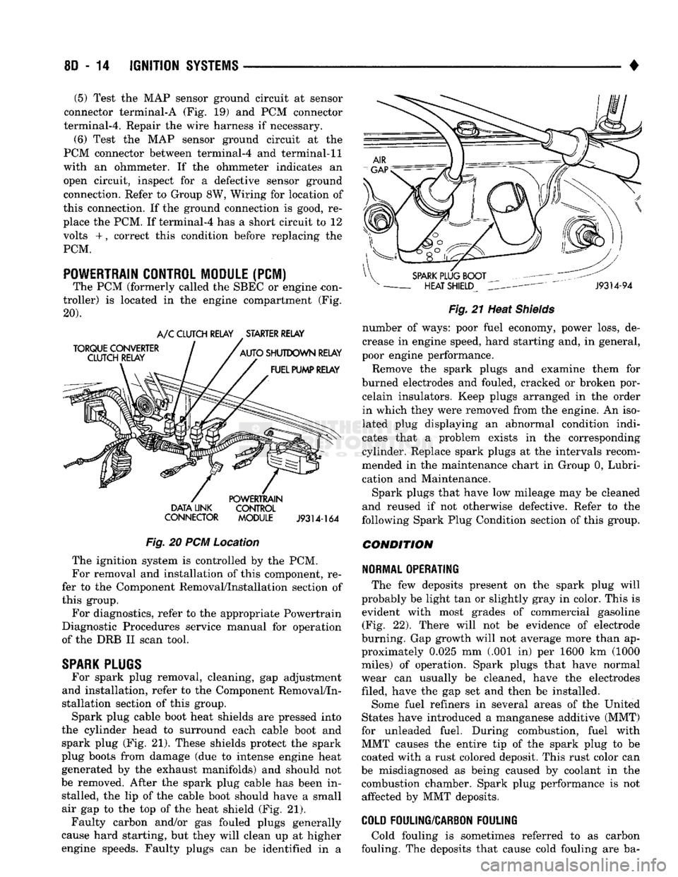
The PCM (formerly called the SBEC or engine -con
troller) is located in the engine compartment (Fig.
20). DATA UNK CONTROL
CONNECTOR MODULE
J9314-164
Fig.
20 PCM Location The ignition system is controlled by the PCM.
For removal and installation of this component, re
fer to the Component Removal/Installation section of
this group.
For diagnostics, refer to the appropriate Powertrain
Diagnostic Procedures service manual for operation
of the DRB II scan tool.
SPARK
PLUGS
For spark plug removal, cleaning, gap adjustment
and installation, refer to the Component Removal/In
stallation section of this group. Spark plug cable boot heat shields are pressed into
the cylinder head to surround each cable boot and
spark plug (Fig. 21). These shields protect the spark
plug boots from damage (due to intense engine heat
generated by the exhaust manifolds) and should not
be removed. After the spark plug cable has been in stalled, the lip of the cable boot should have a small
air gap to the top of the heat shield (Fig. 21). Faulty carbon and/or gas fouled plugs generally
cause hard starting, but they will clean up at higher
engine speeds. Faulty plugs can be identified in a
Fig.
21 Heat
Shields
number of ways: poor fuel economy, power loss, de
crease in engine speed, hard starting and, in general,
poor engine performance.
Remove the spark plugs and examine them for
burned electrodes and fouled, cracked or broken por celain insulators. Keep plugs arranged in the order
in which they were removed from the engine. An iso
lated plug displaying an abnormal condition indi
cates that a problem exists in the corresponding
cylinder. Replace spark plugs at the intervals recom
mended in the maintenance chart in Group 0, Lubri
cation and Maintenance.
Spark plugs that have low mileage may be cleaned
and reused if not otherwise defective. Refer to the
following Spark Plug Condition section of this group.
CONDITION
NORMAL OPERATING
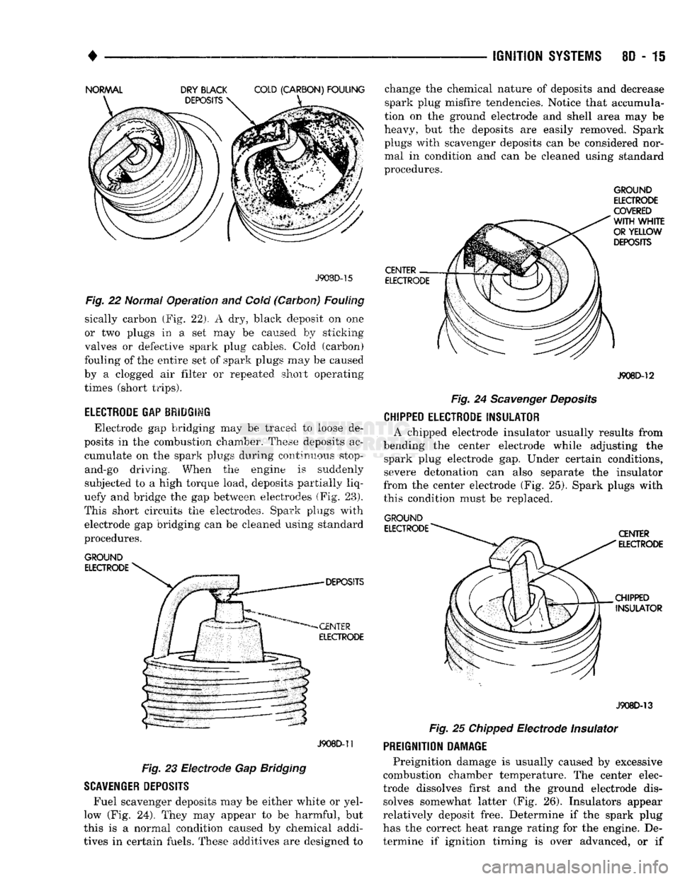
The few deposits present on the spark plug will
probably be light tan or slightly gray in color. This is evident with most grades of commercial gasoline (Fig. 22). There will not be evidence of electrode
burning. Gap growth will not average more than ap proximately 0.025 mm (.001 in) per 1600 km (1000
miles) of operation. Spark plugs that have normal
wear can usually be cleaned, have the electrodes filed, have the gap set and then be installed.
Some fuel refiners in several areas of the United
States have introduced a manganese additive (MMT)
for unleaded fuel. During combustion, fuel with
MMT causes the entire tip of the spark plug to be coated with a rust colored deposit. This rust color can
be misdiagnosed as being caused by coolant in the combustion chamber. Spark plug performance is not affected by MMT deposits.
COLD
FOULING/CARBON FOULING
Cold fouling is sometimes referred to as carbon
fouling. The deposits that cause cold fouling are ba-
Page 366 of 1502
•
IGNITION
SYSTEMS
8D - 15 J908D-15
Fig.
22 Normal Operation and Cold (Carbon) Fouling
sically carbon (Fig. 22). A dry, black deposit on one
or two plugs in a set may be caused by sticking
valves or defective spark plug cables. Cold (carbon)
fouling of the entire set of spark plugs may be caused
by a clogged air filter or .repeated short operating
times (short trips).
ELECTRODE GAP BRIDGIMG
Electrode gap bridging may be traced to loose de
posits in the combustion chamber. These deposits ac cumulate on the spark plugs during continuous stop-
and-go driving. When the engine is suddenly
subjected to a high torque load, deposits partially liq
uefy and bridge the gap between electrodes (Fig. 28).
This short circuits the electrodes. Spark plugs with electrode gap bridging can be cleaned using standard
procedures.
GROUND
ELECTRODE
J908D-11
Fig. 23 Electrode Gap Bridging
SCAVENGER
DEPOSITS
Fuel scavenger deposits may be either white or yel
low (Fig. 24). They may appear to be harmful, but
this is a normal condition caused by chemical addi
tives in certain fuels. These additives are designed to change the chemical nature of deposits and decrease
spark plug misfire tendencies. Notice that accumula
tion on the ground electrode and shell area may be
heavy, but the deposits are easily removed. Spark
plugs with scavenger deposits can be considered nor mal in condition and can be cleaned using standard
procedures.
GROUND
ELECTRODE
COVERED
J908D-12
Fig.
24
Scavenger
Deposits
CHIPPED ELECTRODE
INSULATOR
A chipped electrode insulator usually results from
bending the center electrode while adjusting the spark plug electrode gap. Under certain conditions, severe detonation can also separate the insulator
from the center electrode (Fig. 25). Spark plugs with
this condition must be replaced.
GROUND
J908D-13
Fig.
25
Chipped
Electrode Insulator
PREIGNITION
DAMAGE
Preignition damage is usually caused by excessive
combustion chamber temperature. The center elec
trode dissolves first and the ground electrode dis solves somewhat latter (Fig. 26). Insulators appear
relatively deposit free. Determine if the spark plug
has the correct heat range rating for the engine. De
termine if ignition timing is over advanced, or if
Page 367 of 1502
8D
- 16
IGNITION
SYSTEMS
• other operating conditions are causing engine over
heating. (The heat range rating refers to the operat
ing temperature of a particular type spark plug.
Spark plugs are designed to operate within specific
temperature ranges. This depends upon the thickness and length of the center electrodes porcelain insula
tor.)
GROUND
ELECTRODE
CENTER
ELECTRODE
DISSOLVED
J908D-14 Fig. 26 Preignition Damage
SPARK
PLUG
OVERHEATING
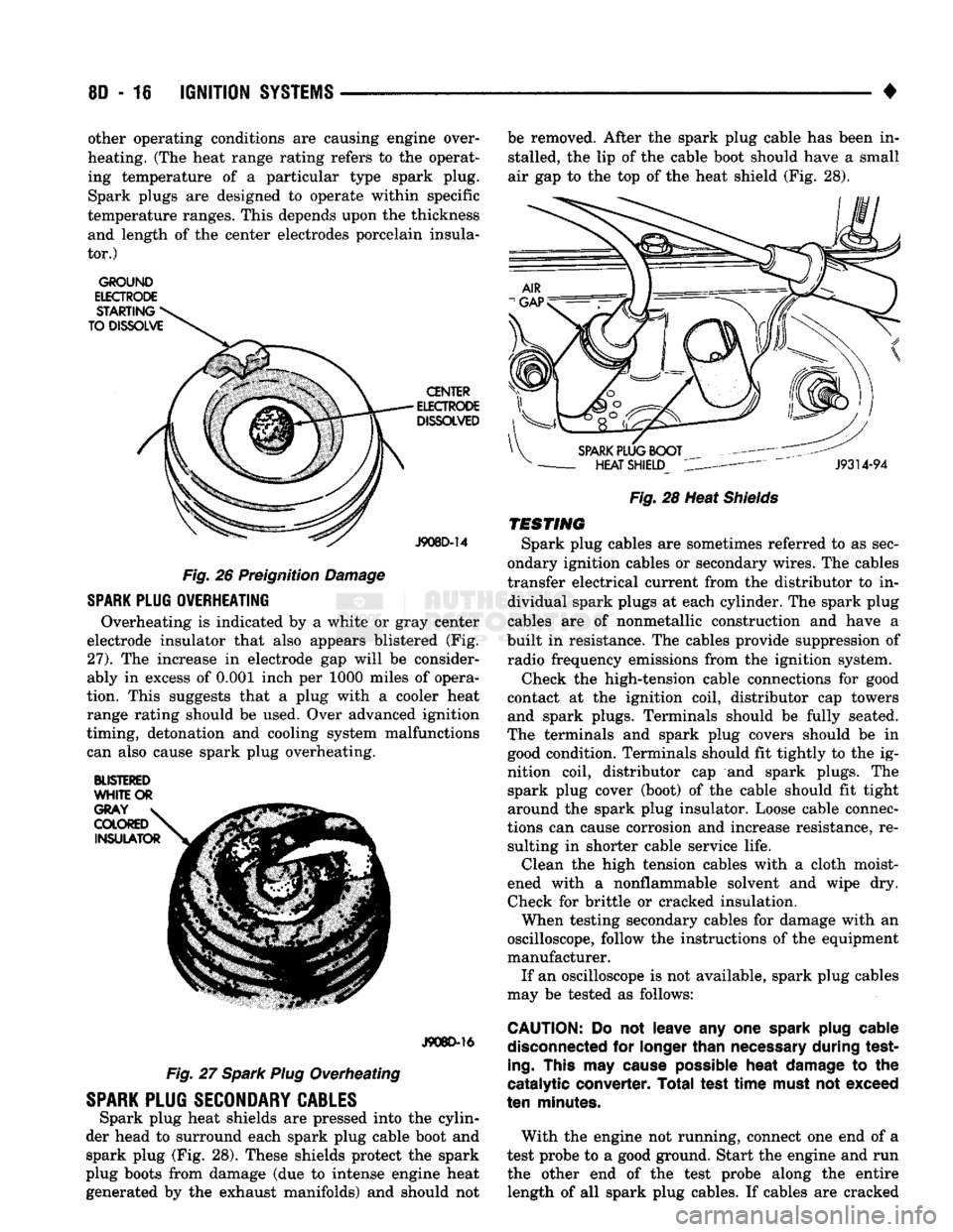
Overheating is indicated by a white or gray center
electrode insulator that also appears blistered (Fig.
27).
The increase in electrode gap will be consider
ably in excess of 0.001 inch per 1000 miles of opera
tion. This suggests that a plug with a cooler heat
range rating should be used. Over advanced ignition
timing, detonation and cooling system malfunctions can also cause spark plug overheating.
BLISTERED
WHITE
OR
J908D-16
Fig. 27 Spark Plug Overheating
SPARK
PLUG
SECONDARY
CABLES
Spark plug heat shields are pressed into the cylin
der head to surround each spark plug cable boot and spark plug (Fig. 28). These shields protect the spark
plug boots from damage (due to intense engine heat
generated by the exhaust manifolds) and should not be removed. After the spark plug cable has been in
stalled, the lip of the cable boot should have a small
air gap to the top of the heat shield (Fig. 28).
Fig.
28 Heat
Shields
TESTING
Spark plug cables are sometimes referred to as sec
ondary ignition cables or secondary wires. The cables
transfer electrical current from the distributor to in dividual spark plugs at each cylinder. The spark plug
cables are of nonmetallic construction and have a
built in resistance. The cables provide suppression of radio frequency emissions from the ignition system.
Check the high-tension cable connections for good
contact at the ignition coil, distributor cap towers and spark plugs. Terminals should be fully seated.
The terminals and spark plug covers should be in good condition. Terminals should fit tightly to the ig
nition coil, distributor cap and spark plugs. The spark plug cover (boot) of the cable should fit tight
around the spark plug insulator. Loose cable connec
tions can cause corrosion and increase resistance, re sulting in shorter cable service life. Clean the high tension cables with a cloth moist
ened with a nonflammable solvent and wipe dry.
Check for brittle or cracked insulation. When testing secondary cables for damage with an
oscilloscope, follow the instructions of the equipment
manufacturer. If an oscilloscope is not available, spark plug cables
may be tested as follows:
CAUTION:
Do not leave any one
spark
plug
cable
disconnected
for
longer
than
necessary
during test
ing.
This
may
cause
possible
heat
damage
to the
catalytic converter. Total test
time
must
not exceed
ten
minutes.
With the engine not running, connect one end of a
test probe to a good ground. Start the engine and run the other end of the test probe along the entire length of all spark plug cables. If cables are cracked
Page 368 of 1502
•
IGNITION SYSTEMS
80-17
or punctured, there will
be a
noticeable spark jump
from
the
damaged area
to the
test probe.
The
cable
running from
the
ignition coil
to the
distributor
cap
can
be
checked
in the
same manner. Cracked, dam aged
or
faulty cables should
be
replaced with resis
tance type cable. This
can be
identified
by the
words ELECTRONIC SUPPRESSION printed
on the
cable
jacket.
Use
an
ohmmeter
to
test
for
open circuits, exces
sive resistance
or
loose terminals. Remove
the
dis
tributor
cap
from
the
distributor.
Do not
remove cables from
cap.
Remove cable from spark plug.
Connect ohmmeter
to
spark plug terminal
end of ca
ble
and to
corresponding electrode
in
distributor
cap.
Resistance should
be 250 to 1000
Ohms
per
inch
of
cable.
If not,
remove cable from distributor
cap
tower and connect ohmmeter
to the
terminal ends
of
cable.
If resistance
is not
within specifications
as
found
in
the Spark Plug Cable Resistance chart, replace
the
cable. Test
all
spark plug cables
in
this manner.
SPARK
PLUG CABLE RESISTANCE
MINIMUM
MAXIMUM
250
Ohms
Per
Inch
1000
Ohms
Per
Inch
3000
Ohms
Per
Foot
12,000
Ohms
Per
Foot
J908D-43 To test ignition coil-to-distributor
cap
cable,
do not
remove
the
cable from
the cap.
Connect ohmmeter
to
rotor button (center contact)
of
distributor
cap and
terminal
at
ignition coil
end of
cable.
If
resistance
is
not within specifications
as
found
in the
Spark Plug
Cable Resistance chart, remove
the
cable from
the
distributor
cap.
Connect
the
ohmmeter
to the
termi
nal ends
of the
cable.
If
resistance
is not
within spec
ifications
as
found
in the
Spark Plug Cable
Resistance chart, replace
the
cable. Inspect
the
igni
tion coil tower
for
cracks, burns
or
corrosion.
For removal
and
installation
of
spark plug cables,
refer
to
Spark Plug Secondary Cables
in the
Compo nent Removal/Installation section.
THROTTLE POSITION
SENSOR
TEST
To perform
a
complete test
of
this sensor
and its
circuitry, refer
to the DRB II
diagnostic scan tool.
Also refer
to the
appropriate Powertrain Diagnostics
Procedures manual.
To
test
the
sensor only, refer
to
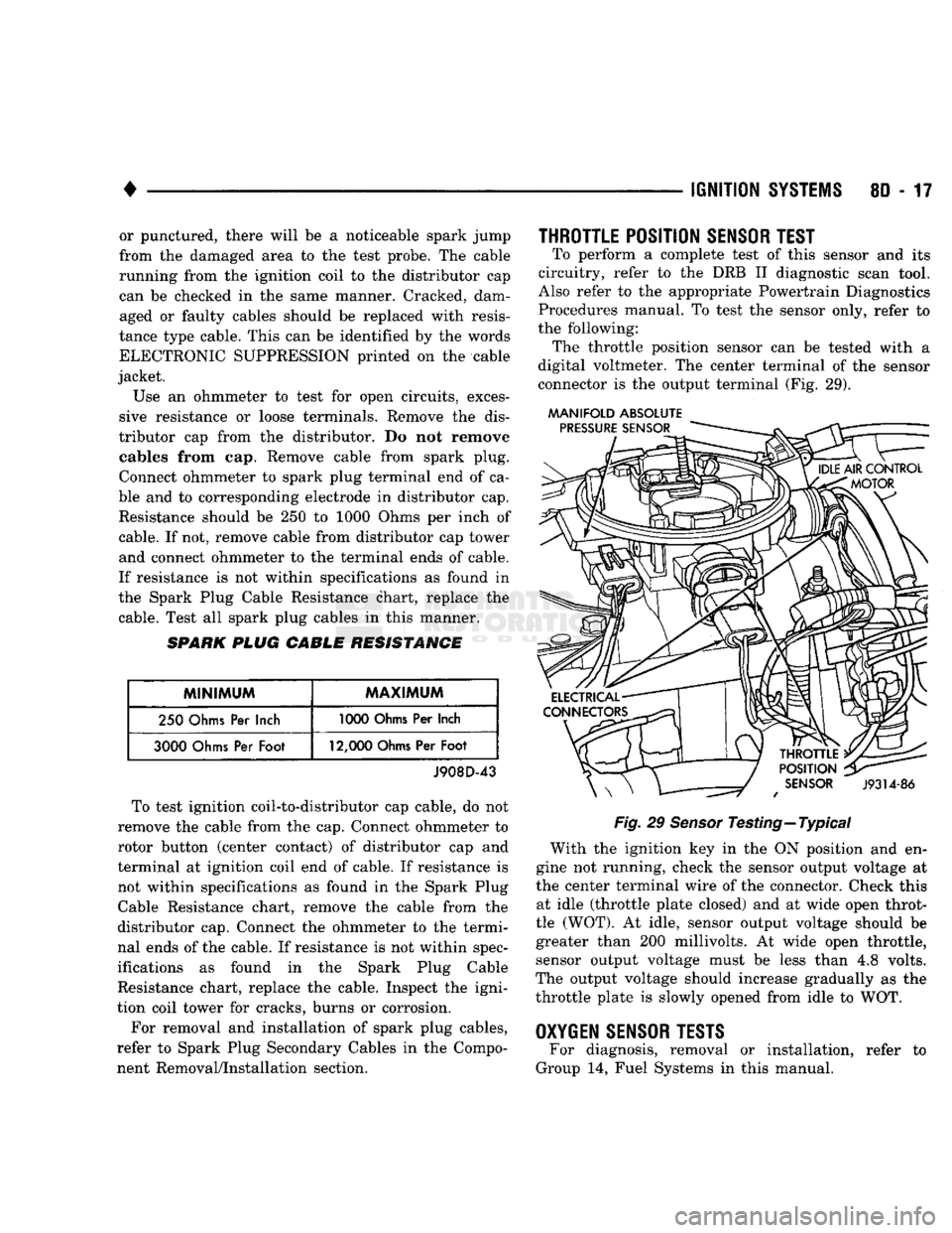
the following: The throttle position sensor
can be
tested with
a
digital voltmeter.
The
center terminal
of the
sensor
connector
is the
output terminal
(Fig. 29).
MANIFOLD ABSOLUTE
Fig.
29
Sensor
Testing—Typical With
the
ignition
key in the ON
position
and en
gine
not
running, check
the
sensor output voltage
at
the center terminal wire
of the
connector. Check this at idle (throttle plate closed)
and at
wide open throt
tle (WOT).
At
idle, sensor output voltage should
be
greater than
200
millivolts.
At
wide open throttle, sensor output voltage must
be
less than
4,8
volts.
The output voltage should increase gradually
as the
throttle plate
is
slowly opened from idle
to WOT.
OXYGEN
SENSOR
TESTS
For diagnosis, removal
or
installation, refer
to
Group
14,
Fuel Systems
in
this manual.
Page 369 of 1502
8D
- 18
IGNITION
SYSTEMS
•
COMPONENT REMGWAL/INSTALLATION
INDEX
page
Automatic
Shut Down (ASD) Relay
18
Camshaft
Position
Sensor
, 18
Crankshaft Position
Sensor
18
Distributor
Service
20
Engine
Coolant Temperature
Sensor
20
General
Information
18
Ignition
Coil
21
page
Intake
Manifold Charge
Air
Temperature
Sensor
. 22
Manifold Absolute Pressure (MAP)
Sensor
..... 22
Oxygen
(02)
Sensor
22
Powertrain
Control
Module (PCM)
22
Spark
Plug Secondary Cables
24
Spark
Plugs
23
Throttle
Position
Sensor
(TPS)
24
GENERAL
INFORMATION
This section
of the
group, Component Removal/In
stallation, will discuss
the
removal
and
installation
of ignition system components. For basic ignition system diagnostics
and
service
adjustments, refer
to the
Diagnostics/Service Proce
dures section
of
this group. For system operation
and
component identification,
refer
to the
Component Identification/System Opera
tion section
of
this group.
AUTOMATIC
SHUT DOWN
(ASb)
RELAY
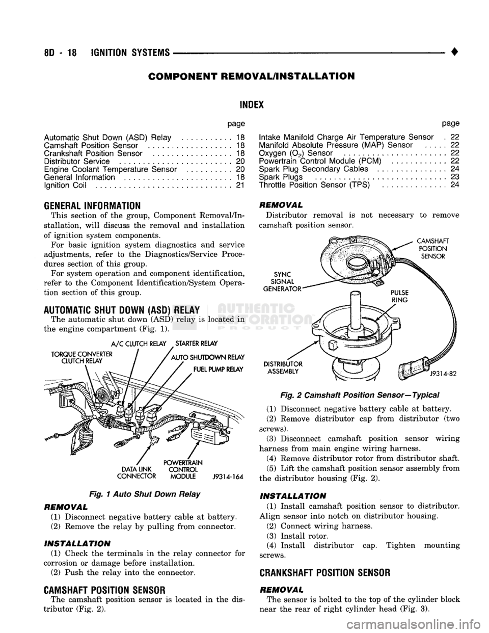
The automatic shut down
(ASD)
relay
is
located
in
the engine compartment
(Fig. 1).
TORQUE CONVERTER
CLUTCH RELAY
A/C
CLUTCH RELAY STARTER RELAY
AUTO
SHUTDOWN RELAY FUEL PUMP RELAY DATA UNK
CONNECTOR POWERTRAIN
CONTROL
MODULE
J9314-164
Fig.
1
Auto
Shut Down
Relay
REMOVAL
(1) Disconnect negative battery cable
at
battery.
(2)
Remove
the
relay
by
pulling from connector.
INSTALLATION
(1) Check
the
terminals
in the
relay connector
for
corrosion
or
damage before installation.
(2)
Push
the
relay into
the
connector.
CAMSHAFT POSITION SENSOR
The camshaft position sensor
is
located
in the
dis
tributor
(Fig. 2).
REMOVAL
Distributor removal
is not
necessary
to
remove
camshaft position sensor.
CAMSHAFT POSITION
SENSOR
SYNC
SIGNAL
GENERATOR
DISTRIBUTOR
ASSEMBLY
J9314-82
Fig.
2
Camshaft Position Sensor—Typical
(1) Disconnect negative battery cable
at
battery.
(2)
Remove distributor
cap
from distributor
(two
screws).
(3) Disconnect camshaft position sensor wiring
harness from main engine wiring harness.
(4) Remove distributor rotor from distributor shaft.
(5)
Lift
the
camshaft position sensor assembly from
the distributor housing
(Fig. 2).
INSTALLATION
(1) Install camshaft position sensor
to
distributor.
Align sensor into notch
on
distributor housing.
(2)
Connect wiring harness.
(3) Install rotor.
(4) Install distributor
cap.
Tighten mounting
screws.
CRANKSHAFT
POSITION SENSOR
REMOVAL The sensor
is
bolted
to the top of the
cylinder block
near
the
rear
of
right cylinder head
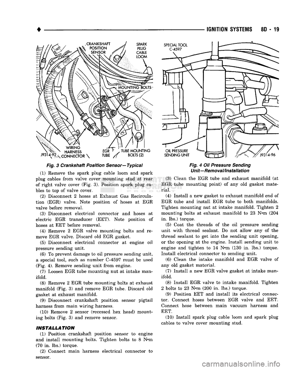
(Fig. 3).
Page 370 of 1502
•
Fig.
3 Crankshaft Position Sensor—Typical (1) Remove the spark plug cable loom and spark
plug cables from valve cover mounting stud at rear of right valve cover (Fig. 3). Position spark plug ca
bles to top of valve cover.
(2) Disconnect 2 hoses at Exhaust Gas Recircula
tion (EGR) valve. Note position of hoses at EGR valve before removal.
(3) Disconnect electrical connector and hoses at
electric EGR transducer (EET). Note position of
hoses at EET before removal.
(4) Remove 2 EGR valve mounting bolts and re
move EGR valve. Discard old EGR gasket.
(5) Disconnect electrical connector at engine oil
pressure sending unit.
(6) To prevent damage to oil pressure sending unit,
a special tool, such as number C-4597 must be used (Fig. 4). Remove sending unit from engine.
(7) Loosen EGR tube mounting nut at intake man
ifold.
(8) Remove 2 EGR tube mounting bolts at exhaust
manifold (Fig. 3) and remove EGR tube. Discard old
gasket at exhaust manifold.
(9) Disconnect crankshaft position sensor pigtail
harness from main wiring harness.
(10) Remove 2 sensor (recessed hex head) mount
ing bolts (Fig. 3) and remove sensor.
INSTALLATION
(1) Position crankshaft position sensor to engine
and install mounting bolts. Tighten bolts to 8 N#m (70 in. lbs.) torque. (2) Connect main harness electrical connector to
sensor.
IGNITION
SYSTEMS
80-19
Fig.
4 Oil
Pressure
Sending
Unit—Removal/Installation (3) Clean the EGR tube and exhaust manifold (at
EGR tube mounting point) of any old gasket mate
rial.
(4) Install a new gasket to exhaust manifold end of
EGR tube and install EGR tube to both manifolds.
Tighten mounting nut at intake manifold. Tighten 2 mounting bolts at exhaust manifold to 23 N#m (204 in. lbs.) torque.
(5) Coat the threads of the oil pressure sending
unit with thread sealant. Do not allow any of the
thread sealant to get into the sending unit opening, or the opening at the engine. Install sending unit to
engine and tighten to 14 N»m (130 in. lbs.) torque.
Install electrical connector to sending unit.
(6) Clean the intake manifold and EGR valve of
any old gasket material.
(7) Install a new EGR valve gasket at intake man
ifold. (8) Install EGR valve to intake manifold. Tighten
2 bolts to 23 N«m (200 in. lbs.) torque.
(9) Position EET and install its electrical connec
tor. Connect hoses between EGR valve and EET. Connect hose between main vacuum harness and
EET.
(10) Install spark plug cable loom and spark plug
cables to valve cover mounting stud.