DODGE TRUCK 1993 Service Repair Manual
Manufacturer: DODGE, Model Year: 1993, Model line: TRUCK, Model: DODGE TRUCK 1993Pages: 1502, PDF Size: 80.97 MB
Page 341 of 1502

Page 342 of 1502
• BATTERY/STARTER/GENERATOR
SERVICE
8B - 1
CONTENTS
page page
BATTERY
SERVICE
PROCEDURES
1 SPECIFICATIONS 9
GENERATOR
SERVICE
6 STARTER
SERVICE
PROCEDURES
4
BATTERY SERVICE PROCEDURES
GENERAL
INFORMATION This section will cover the Battery service, re
moval, and installation procedures only. For diagnos
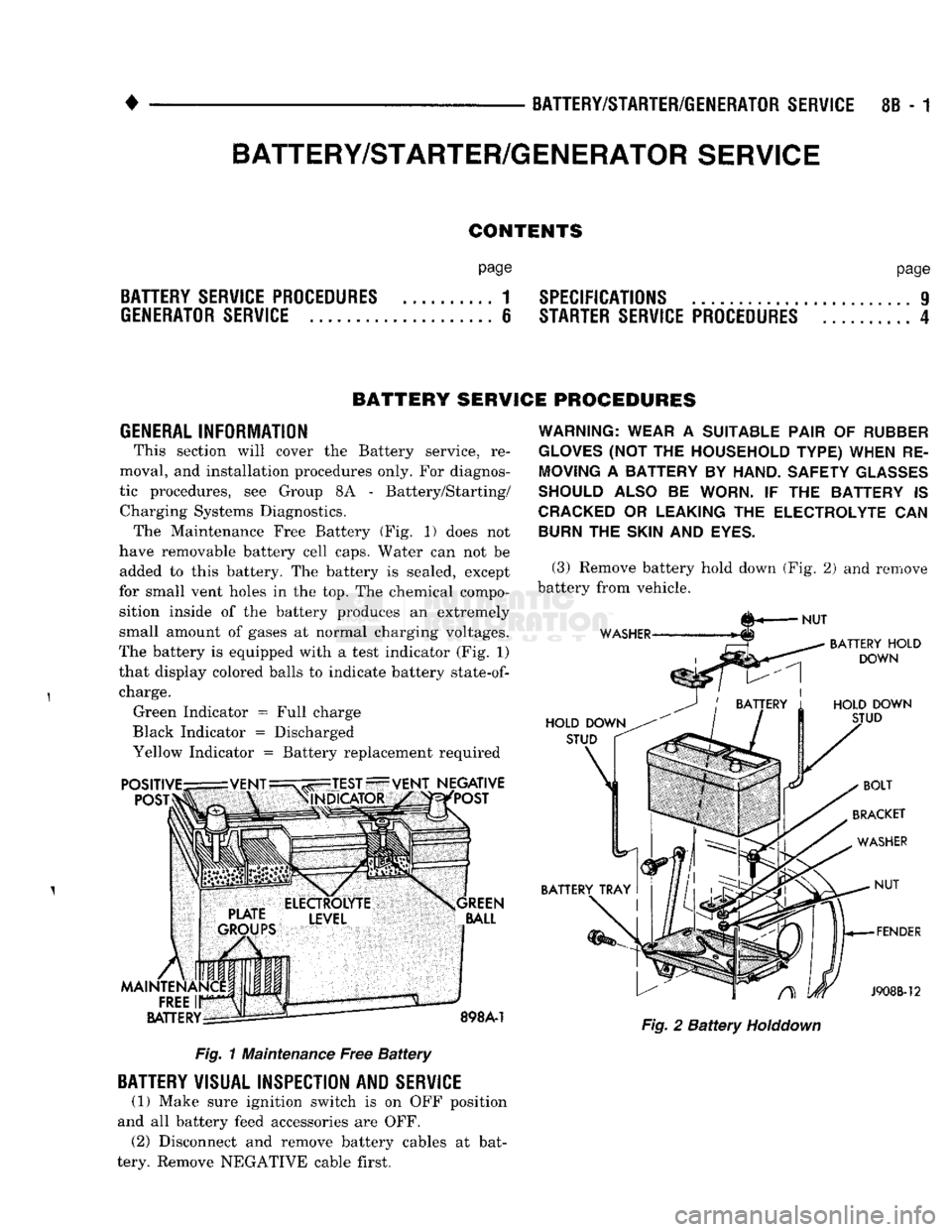
tic procedures, see Group 8A - Battery/Starting/ Charging Systems Diagnostics. The Maintenance Free Battery (Fig. 1) does not
have removable battery cell caps. Water can not be added to this battery. The battery is sealed, except
for small vent holes in the top. The chemical compo sition inside of the battery produces an extremely
small amount of gases at normal charging voltages.
The battery is equipped with a test indicator (Fig. 1)
that display colored balls to indicate battery
state-of-
charge. Green Indicator = Full charge
Black Indicator = Discharged
Yellow Indicator = Battery replacement required Fig. 1 Maintenance Free Battery
BATTERY
VISUAL INSPECTION AND
SERVICE
(1) Make sure ignition switch is on OFF position
and all battery feed accessories are OFF. (2) Disconnect and remove battery cables at bat
tery. Remove NEGATIVE cable first.
WARNING: WEAR
A
SUITABLE PAIR
OF
RUBBER
GLOVES
(NOT THE
HOUSEHOLD TYPE) WHEN
RE
MOVING
A
BATTERY
BY
HAND. SAFETY
GLASSES
SHOULD ALSO
BE
WORN.
IF THE
BATTERY
IS
CRACKED
OR
LEAKING
THE
ELECTROLYTE
CAN
BURN
THE
SKIN
AND
EYES.
(3) Remove battery hold down (Fig. 2) and remove
battery from vehicle. Fig. 2 Battery
Holddown
BATTERY/STARTER/GENERATOR
SERVICE
Page 343 of 1502
8B
- 2
BATTERY/STARTER/GENERATOR SERVICE
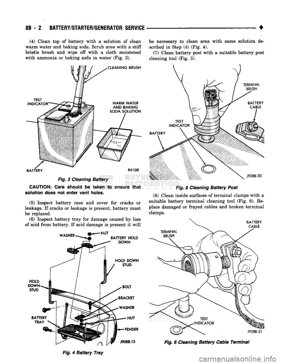
• (4) Clean top of battery with a solution of clean
warm water and baking soda. Scrub area with a stiff
bristle brush and wipe off with a cloth moistened
with ammonia or baking soda in water (Fig. 3). be necessary to clean area with same solution de
scribed in Step (4) (Fig. 4).
(7) Clean battery post with a suitable battery post
cleaning tool (Fig. 5).
TERMINAL
BRUSH
TEST
INDICATOR
BATTERY Fig.
3
Cleaning
Battery
CAUTION:
Care should
be
taken
to
ensure
that
solution
does
not
enter
vent holes.
(5) Inspect battery case and cover for cracks or
leakage. If cracks or leakage is present, battery must
be replaced.
(6) Inspect battery tray for damage caused by loss
of acid from battery. If acid damage is present it will J928B-30
Fig.
5
Cleaning
Battery
Post
(8)
Clean inside surfaces of terminal clamps with a
suitable battery terminal cleaning tool (Fig. 6). Re
place damaged or frayed cables and broken terminal clamps.
BATTERY
CABLE
WASHER
NUT
BATTERY
HOLD
DOWN
HOLD DOWN STUD HOLD
DOWN
STUD
BATTERY TRAY
J928B-3f A
Fig.
4
Battery
Tray
J908B-13
Fig.
6
Cleaning
Battery
Cable Terminal
Page 344 of 1502
•
BATTERY/STARTER/GENERATOR
SERVICE
8B - 3
Fig.
7
Battery
Cables
Disconnected
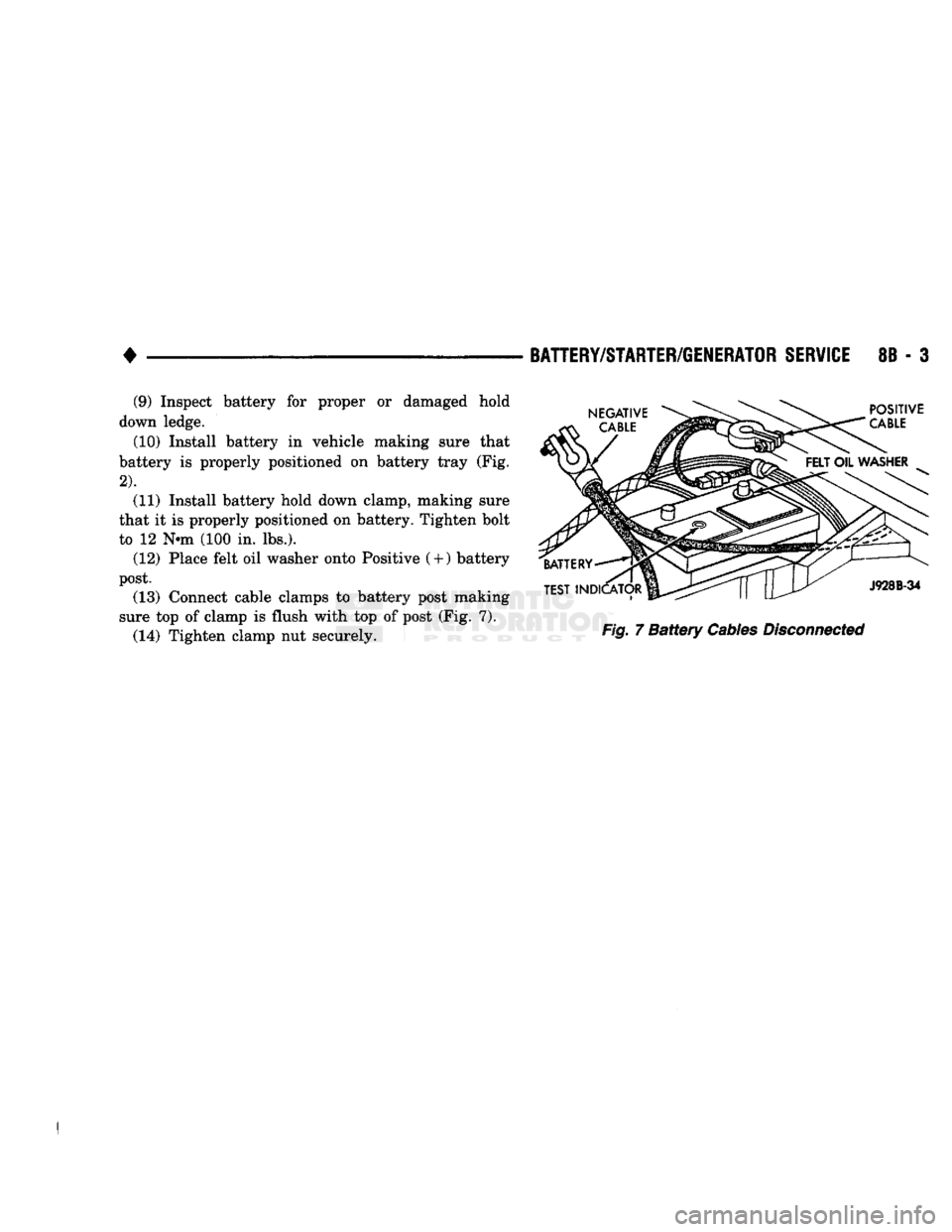
(9) Inspect battery for proper or damaged hold
down ledge.
(10) Install battery in vehicle making sure that
battery is properly positioned on battery tray (Fig.
2).
(11) Install battery hold down clamp, making sure
that it is properly positioned on battery. Tighten bolt
to 12 N-m (100 in. lbs.). (12) Place felt oil washer onto Positive
(
+
)
battery
post. (13) Connect cable clamps to battery post making
sure top of clamp is flush with top of post (Fig. 7). (14) Tighten clamp nut securely.
Page 345 of 1502
8B
- 4
BATTERY/STARTER/GENERATOR SERVICE
•
STARTER SERVICE PROCEDURES
GENERAL INFORMATION
This section will cover the Starter removal and in
stallation. For diagnostic procedures, see Group 8A -
Battery/Starting/Charging Systems Diagnostics.
STARTING
SYSTEM DESCRIPTION
The starter system circuits consist of:
• a battery
• engine starter motor and solenoid
• starter relay
• ignition switch
© park/neutral position switch (automatic transmis sion)
• clutch interlock switch (manual transmission-die-
sel)
• connecting wires and battery cables. Turning the ignition switch to the start position,
causes the starter relay points to close allowing cur
rent to energize solenoid windings. This causes sole
noid plunger and clutch shift lever to move engaging
clutch pinion gear into ring gear. At the same time
the solenoid contacts close causing starter motor to
crank. As soon as engine starts running clutch pin ion gear overruns to protect starter armature from
damage due to excessive speed. Once the engine starts running, the ignition key switch should be im
mediately returned to the run position to prevent ex
cessive starter motor damage.
WARNING:
ALWAYS DISCONNECT NEGATIVE
CA
BLE FROM
BATTERY
BEFORE SERVICING
THE
STARTER.
STARTER
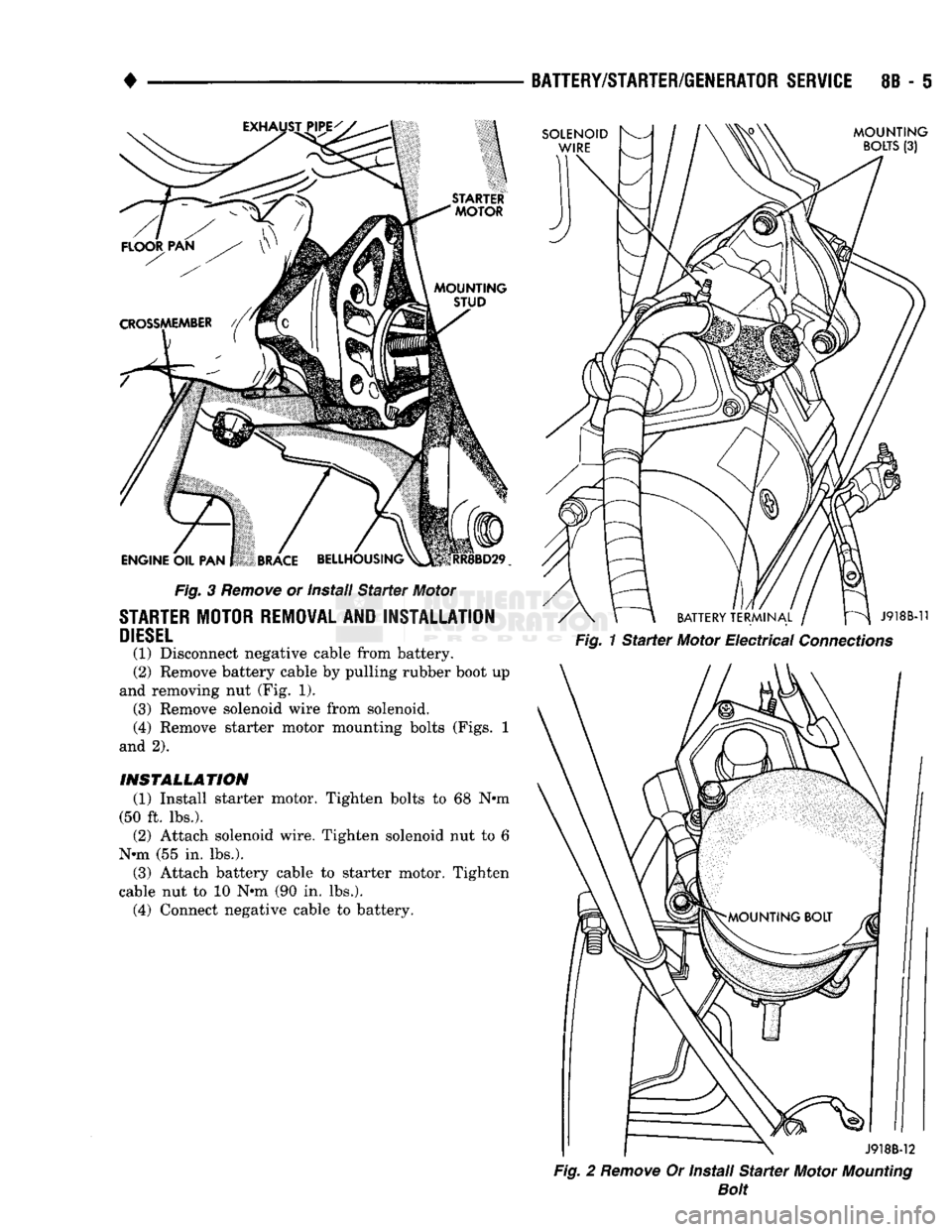
MOTOR REMOVAL AND INSTALLATION EXCEPT DIESEL
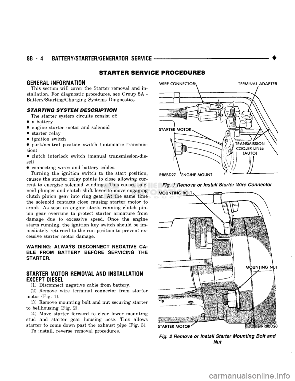
(1) Disconnect negative cable from battery.
(2) Remove wire terminal connector from starter
motor (Fig. 1). (3) Remove mounting bolt and nut securing starter
to bellhousing (Fig. 2).
(.4) Move starter forward to clear lower mounting
stud and starter gear housing nose. This allows
starter to come down past the exhaust pipe (Fig. 3). To install, reverse removal procedures.
Fig.
2
Remove
or Install
Starter
Mounting
Bolt
and
Nut
Page 346 of 1502
•
Fig.
3
Remove
or Install
Starter
Motor
STARTER
MOTOR REMOVAL AND INSTALLATION
DIESEL
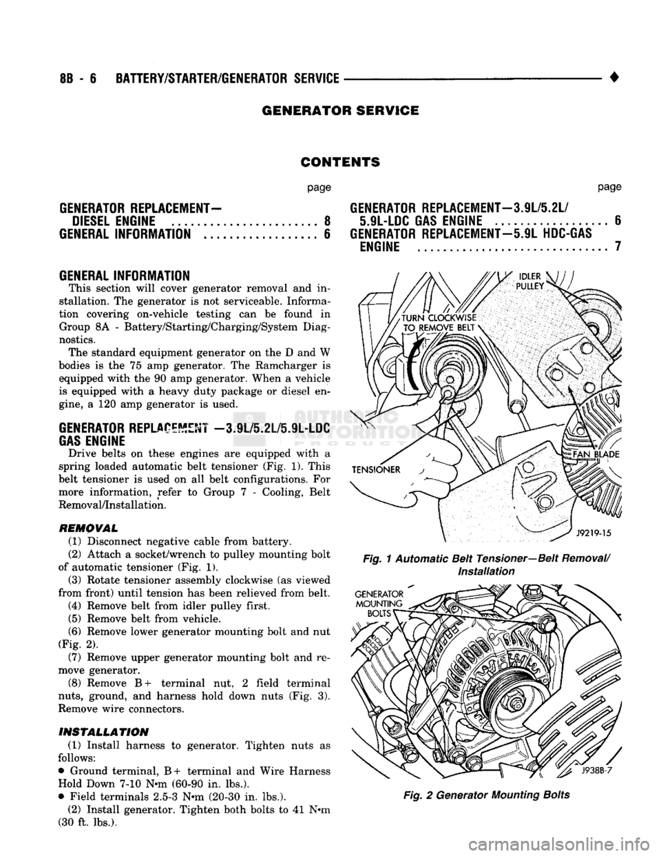
(1) Disconnect negative cable from battery.
(2) Remove battery cable by pulling rubber boot up
and removing nut (Fig. 1). (3) Remove solenoid wire from solenoid.
(4) Remove starter motor mounting bolts (Figs. 1
and 2).
INSTALLATION
(1) Install starter motor. Tighten bolts to 68 N»m
(50 ft. lbs.). (2) Attach solenoid wire. Tighten solenoid nut to 6
N»m (55 in. lbs.). (3) Attach battery cable to starter motor. Tighten
cable nut to 10 N*m (90 in. lbs.). (4) Connect negative cable to battery.
BATTERY/STARTER/GENERATOR SERVICE
8B - 5
Fig.
2
Remove
Or Install
Starter
Motor
Mounting
Bolt
Page 347 of 1502
8B
- 6
BATTERY/STARTER/GENERATOR
SERVICE
•
GENERATOR SERVICE
CONTENTS
page
GENERATOR
REPLACEMENT-
DIESEL
ENGINE
8
GENERAL
INFORMATION
6
GENERAL
INFORMATION This section will cover generator removal
and in
stallation.
The
generator
is not
serviceable. Informa
tion covering on-vehicle testing
can be
found
in
Group
8A -
Battery/Starting/Charging/System Diag
nostics. The standard equipment generator
on the D and W
bodies
is the 75 amp
generator.
The
Ramcharger
is
equipped with
the 90 amp
generator. When
a
vehicle
is equipped with
a
heavy duty package
or
diesel
en
gine,
a 120 amp
generator
is
used.
GENERATOR
REPLACEMENT
-3.9L/5.2L/5.9L-LDC
GAS
ENGINE
Drive belts
on
these engines
are
equipped with
a
spring loaded automatic belt tensioner
(Fig. 1).
This
belt tensioner
is
used
on all
belt configurations.
For
more information, refer
to
Group
7 -
Cooling, Belt
Removal/Installation.
REMOVAL
(1) Disconnect negative cable from battery.
(2) Attach
a
socket/wrench
to
pulley mounting bolt
of automatic tensioner
(Fig. 1).
(3) Rotate tensioner assembly clockwise
(as
viewed
from front) until tension
has
been relieved from belt. (4) Remove belt from idler pulley first.
(5) Remove belt from vehicle.
(6)
Remove lower generator mounting bolt
and nut
(Fig.
2).
(7) Remove upper generator mounting bolt
and re
move generator.
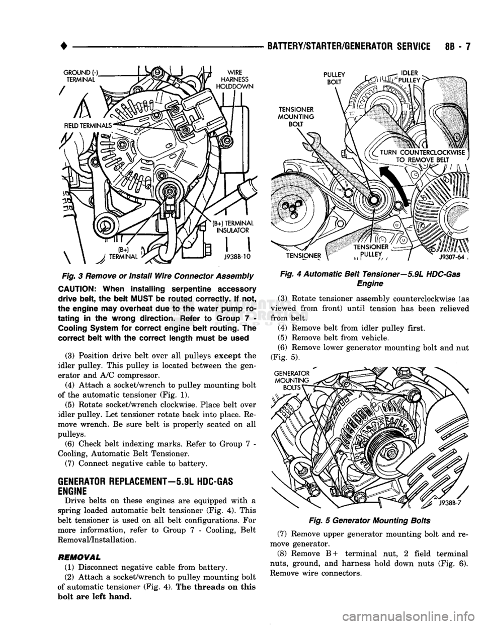
(8) Remove
B+
terminal
nut, 2
field terminal
nuts,
ground,
and
harness hold down nuts
(Fig. 3).
Remove wire connectors.
INSTALLATION
(1) Install harness
to
generator. Tighten nuts
as
follows:
• Ground terminal,
B+
terminal
and
Wire Harness Hold Down
7-10 N*m
(60-90
in.
lbs.).
• Field terminals
2.5-3 N-m
(20-30
in.
lbs.). (2) Install generator. Tighten both bolts
to 41 N»m
(30
ft.
lbs.).
page
GENERATOR
REPLACEMENT—3.9L/5.2L/
5.9L-LDC
GAS
ENGINE
6
GENERATOR
REPLACEMENT—5.9L
HDC-GAS
ENGINE
7
Fig.
1 Automatic Belt Tensioner—Belt
Removal/
Installation
Fig.
2
Generator
Mounting
Bolts
Page 348 of 1502
•
Fig.
3
Remove
or install
Wire
Connector
Assembly
CAUTION:
When
installing
serpentine
accessory
drive
belt,
the
belt
MUST
be
routed
correctly.
If not,
the engine may overheat due to the
water
pump ro
tating
in the wrong
direction.
Refer to Group 7 -
Cooling
System
for
correct
engine
belt
routing.
The
correct
belt
with
the
correct
length
must be
used
(3) Position drive belt over all pulleys except the
idler pulley. This pulley is located between the gen
erator and A/C compressor.
(4) Attach a socket/wrench to pulley mounting bolt
of the automatic tensioner (Fig. 1).
(5)
Rotate socket/wrench clockwise. Place belt over
idler pulley. Let tensioner rotate back into place. Re
move wrench. Be sure belt is properly seated on all
pulleys.
(6) Check belt indexing marks. Refer to Group 7 -
Cooling, Automatic Belt Tensioner.
(7) Connect negative cable to battery.
GENERATOR
REPLACEMENT—5.9L
HDC-GAS
ENGINE
Drive belts on these engines are equipped with a
spring loaded automatic belt tensioner (Fig. 4). This
belt tensioner is used on all belt configurations. For more information, refer to Group 7 - Cooling, Belt
Removal/Installation.
REMOVAL
(1) Disconnect negative cable from battery.
(2) Attach a socket/wrench to pulley mounting bolt
of automatic tensioner (Fig. 4). The threads on this
bolt are left hand.
BATTERY/STARTER/GENERATOR
SERVICE
8B - 7
Fig.
4 Automatic Belt Tensioner—5.9L
HDC-Gas
Engine
(3) Rotate tensioner assembly counterclockwise (as
viewed from front) until tension has been relieved
from belt.
(4) Remove belt from idler pulley first.
(5) Remove belt from vehicle.
(6) Remove lower generator mounting bolt and nut
(Fig. 5).
Fig.
5 Generator
Mounting
Bolts
(7) Remove upper generator mounting bolt and re
move generator.
(8) Remove B+ terminal nut, 2 field terminal
nuts,
ground, and harness hold down nuts (Fig. 6).
Remove wire connectors.
Page 349 of 1502
8B
- 8
BATTERY/STARTER/GENERATOR
SERVICE
•
Fig.
6
Remove
or Install
Wire
Connector
Assembly
INSTALLATION
(1) Install harness to generator. Tighten nuts as
follows:
• Ground terminal, B+ terminal and Wire Harness
Hold Down 7-10 Nun (60-90 in. lbs.).
• Field terminals 2.5-3 Nun (20-30 in. lbs.).
(2) Install generator. Tighten both bolts to 41 Nun
(30 ft. lbs.).
CAUTION:
When
installing
the
serpentine
accessory
drive
belt,
the
belt
MUST
be
routed
correctly.
If not,
the
engine
may
overheat
due to the
water
pump
ro
tating
in the
wrong
direction.
Refer
to
Group
7 -
Cooling
System
for
correct
engine
belt
routing.
The
correct
belt
with
the
correct
length
must
be
used
(3) Position drive belt over all pulleys except wa
ter pump pulley.
(4) Attach a 3/8 inch rachet to tensioner.
(5) Rotate ratchet and belt tensioner counterclock
wise.
Place belt over water pump pulley. Let ten sioner rotate back into place. Remove ratchet. Be
sure belt is properly seated on all pulleys.
(6) Connect negative cable to battery.
GENERATOR
REPLACEMENT—DIESEL
ENGINE
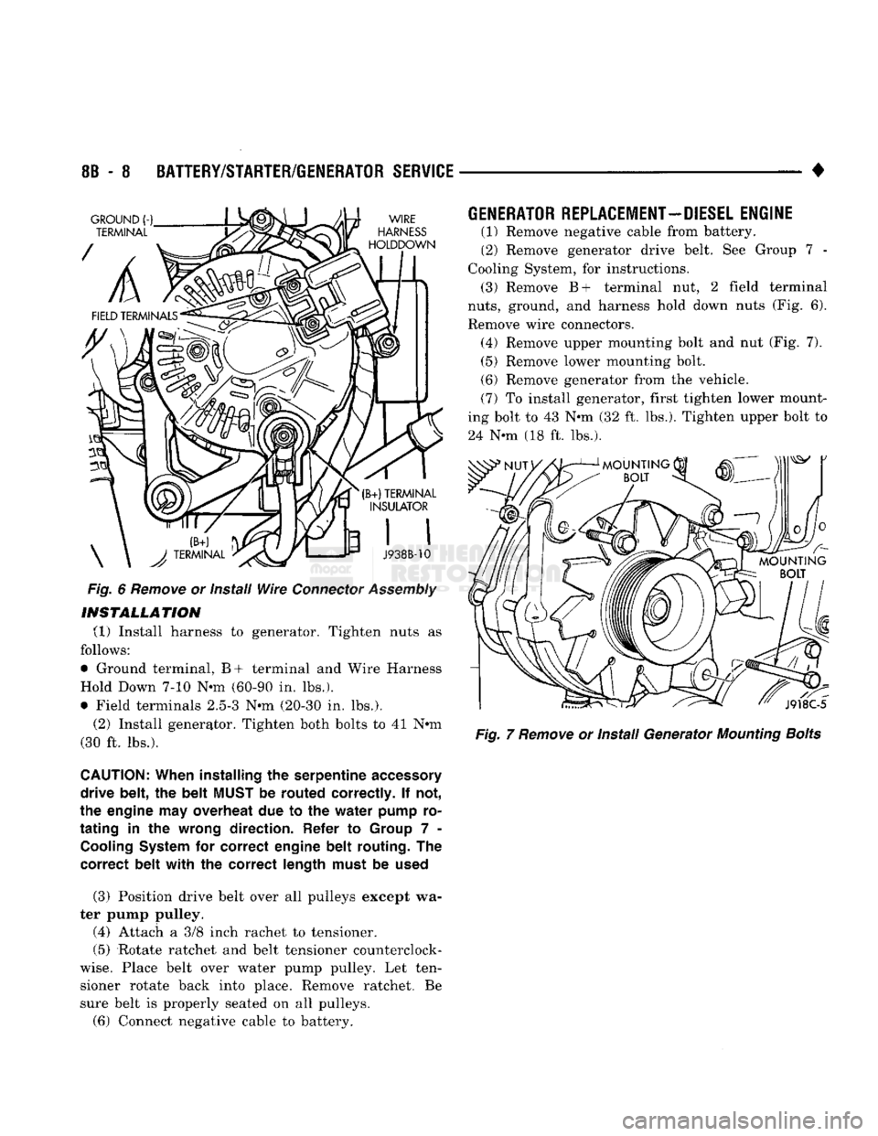
(1) Remove negative cable from battery.
(2) Remove generator drive belt. See Group 7 -
Cooling System, for instructions. (3) Remove B+ terminal nut, 2 field terminal
nuts,
ground, and harness hold down nuts (Fig. 6).
Remove wire connectors. (4) Remove upper mounting bolt and nut (Fig. 7). (5) Remove lower mounting bolt.
(6) Remove generator from the vehicle.
(7) To install generator, first tighten lower mount
ing bolt to 43 Nun (32 ft. lbs.). Tighten upper bolt to
24 Nun (18 ft. lbs.).
Fig.
7
Remove
or Install Generator
Mounting
Bolts
Page 350 of 1502
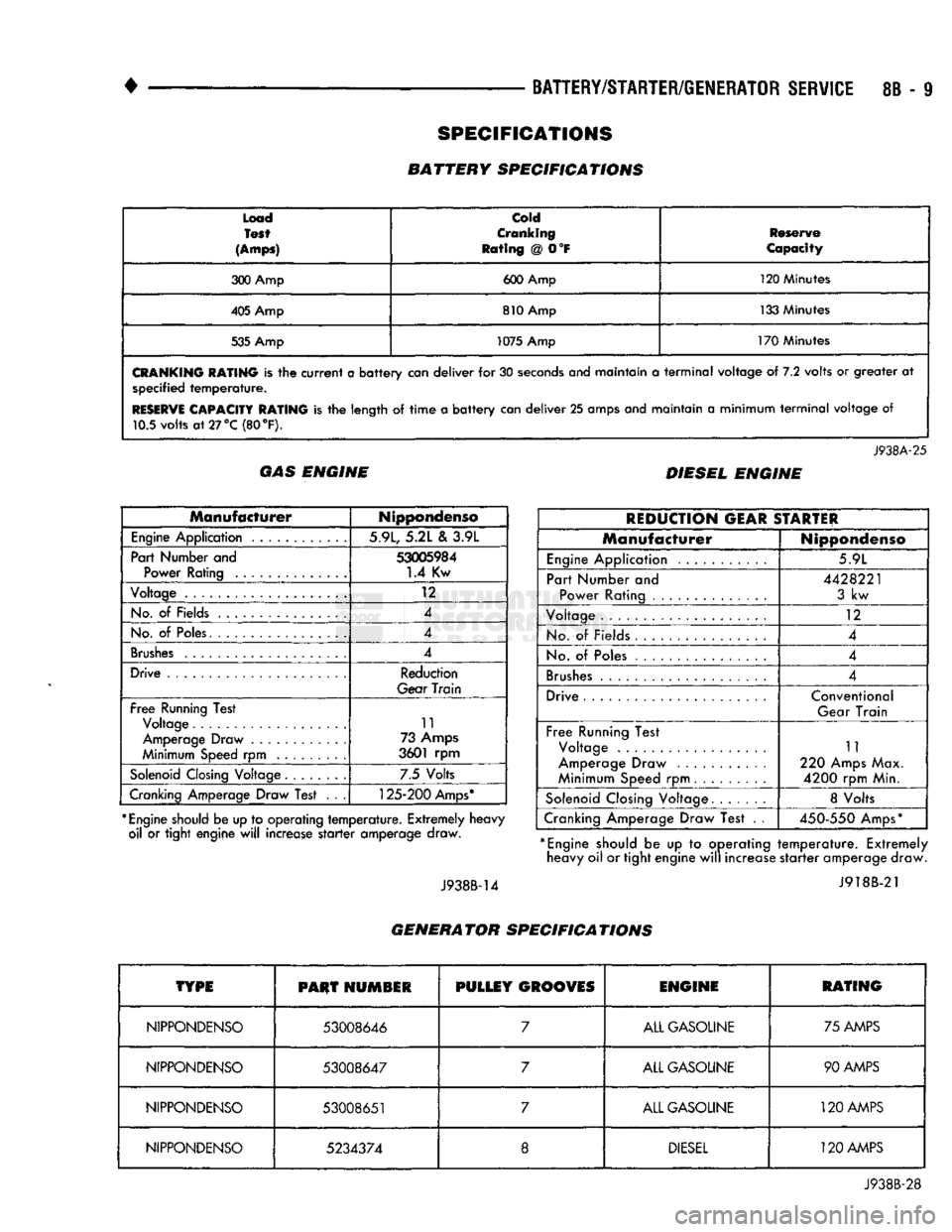
•
BATTERY/STARTER/GENERATOR
SERVICE
8B - 9
Load
Test
(Amps)
cold
Cranking
Rating
@ 0°F
Reserve
Capacity
300 Amp 600 Amp 120 Minutes
405 Amp 810 Amp 133 Minutes
535 Amp 1075 Amp
170 Minutes
CRANKING
RATING
is the
current
a
battery
can
deliver
for 30
seconds
anej
maintain
a
terminal
voltage
of 7.2
volts
or
greater
at
specified
temperature.
RESERVE
CAPACITY RATING
is the
length
of
time
a
battery
can
deliver
25
amps and maintain
a
minimum
terminal
voltage
of
10.5 volts
at
27 °C (80
°F).
J938A-25
GAS ENGINE DIESEL ENGINE
Manufacturer
Nippondenso
Engine
Application 5.9L, 5.2L
&
3.9L
Part Number and
53005984
Power Rating
1.4
Kw
Voltage
12
No.
of
Fields 4
No.
of
Poles. 4
Brushes
4
Drive Reduction
Gear
Train
Free
Running Test Voltage 11
Amperage Draw 73 Amps
Minimum Speed
rpm
3601
rpm
Solenoid
Closing Voltage 7.5 Volts
Cranking Amperage Draw Test
. . .
125-200
Amps*
*
Engine
should be up to operating
temperature.
Extremely heavy oil
or
tight engine
will
increase
starter
amperage draw.
J938B-14
REDUCTION
GEAR
STARTER
Manufacturer
Nippondenso
Engine
Application 5.9L
Part Number
and
Power Rating
4428221
3
kw
Voltage
12
No.
of
Fields
4
No.
of
Poles 4
Brushes
4
Drive Conventional
Gear Train
Free
Running Test Voltage
Amperage Draw
Minimum Speed
rpm
11
220 Amps Max.
4200
rpm Min.
Solenoid
Closing Voltage 8 Volts
Cranking Amperage Draw Test
. .
450-550
Amps*
*
Engine
should
be up to
operating
temperature.
Extremely heavy oil or tight engine
will
increase
starter
amperage draw.
J918B-21
GENERATOR SPECIFICATIONS
TYPE
PHUT
HUMSIR
PULLEY
GROOVES
ENGINE
RATING
NIPPONDENSO
53008646
7
ALL GASOLINE 75 AMPS
NIPPONDENSO
53008647
7
ALL GASOLINE 90 AMPS
NIPPONDENSO
53008651
7
ALL GASOLINE
120
AMPS
NIPPONDENSO
5234374
8
DIESEL
120 AMPS
J938B-28
SPECIFICATIONS
BATTERY SPECIFICATIONS