DODGE TRUCK 1993 Service Repair Manual
Manufacturer: DODGE, Model Year: 1993, Model line: TRUCK, Model: DODGE TRUCK 1993Pages: 1502, PDF Size: 80.97 MB
Page 421 of 1502
- 6
VEHICLE SPEED CONTROL SYSTEM
• £
UNIT
DISENGAGES
ON ROUGH ROAD
IMPROPER
ADJUSTMENT
OF
STOP LAMP AND SPEED
CONTROL SWITCH*
i
FAULTY
ELECTRICAL CIRCUIT
ENGINE DOES
NOT RETURN
TO
NORMAL IDLE
SPEED
CONTROL
THROTTLE
CABLE
KINKED OR DAAAAGED
STANDARD
THROTTLE
LINKAGE FAULTS
NO RESUME WHEN
BUTTON
IS
PRESSED
DRIVE VEHICLE OVER
ROUGH ROAD
±
TAP BRAKE PEDAL
LIGHTLY,
SPEED
CONTROL SHOULD
DISENGAGE
SPEED
CONTROL
DISENGAGES
PUSH RESUME/ACCEL SWITCH VEHICLE
SHOULD RESUME PREVIOUSLY
MEMORIZED SPEED
VEHICLE RESUMES
SPEED
DEPRESS
BRAKE
PEDAL,
SPEED CONTROL
SHOULD DISENGAGE NO SYSTEM
DISENGAGEMENT
WHEN MAKE PEDAL
IS
DEPRESSED
DEFECTIVE OR
IMPROPERLY ADJSUTED STOP LAMP
AND
SPEED
CONTROL SWITCH
1
1
SPEED
CONTROL
THROTTLE
CABLE
KINKED
OR
DAAAAGED
1
FAULTY
ELECTRICAL CIRCUIT*
1
DEFECTIVE SERVO
SPEED
CONTROL
DISENGAGES
DEFECTIVE SWITCH
FAULTY
ELECTRICAL CIRCUIT*
1
NO SYSTEM
DISENGAGE
WHEN BRAKE PEDAL
IS
DEPRESSED
SPEED
CONTROL
SYSTEM
OK
1
r
DEFECTIVE ENGINE CONTROLLER
* r
FAULTY
ELECTRICAL CIRCUIT*
r
STICKY BRAKE SWITCH RESUM
ISPO
BELOW*
E
SPEED
SSIBLE
10
M.P.H.
1
DEFECTIVE DISTANCE
SENSOR
f
DEFECTIVE
ENGINE CONTROLLER
J928H-14 DIESEL ENGINE CONTINUED
Page 422 of 1502
•
VEHICLE
SPEED
CONTROL SYSTEM
8H - 7
TEST
PROCEDURES
INDEX
page
Checking
for
Diagnostic
Trouble
Code
7
General
Information
7
Inoperative
System
7
Road
Test
7
Speed
Control
Cable Adjustment—Diesel Engine
. 9
Speed
Control
Cable
Attachment
10
GENERAL
INFORMATION
Before starting diagnosis and repair procedures for
a speed control malfunction, verify that the speed
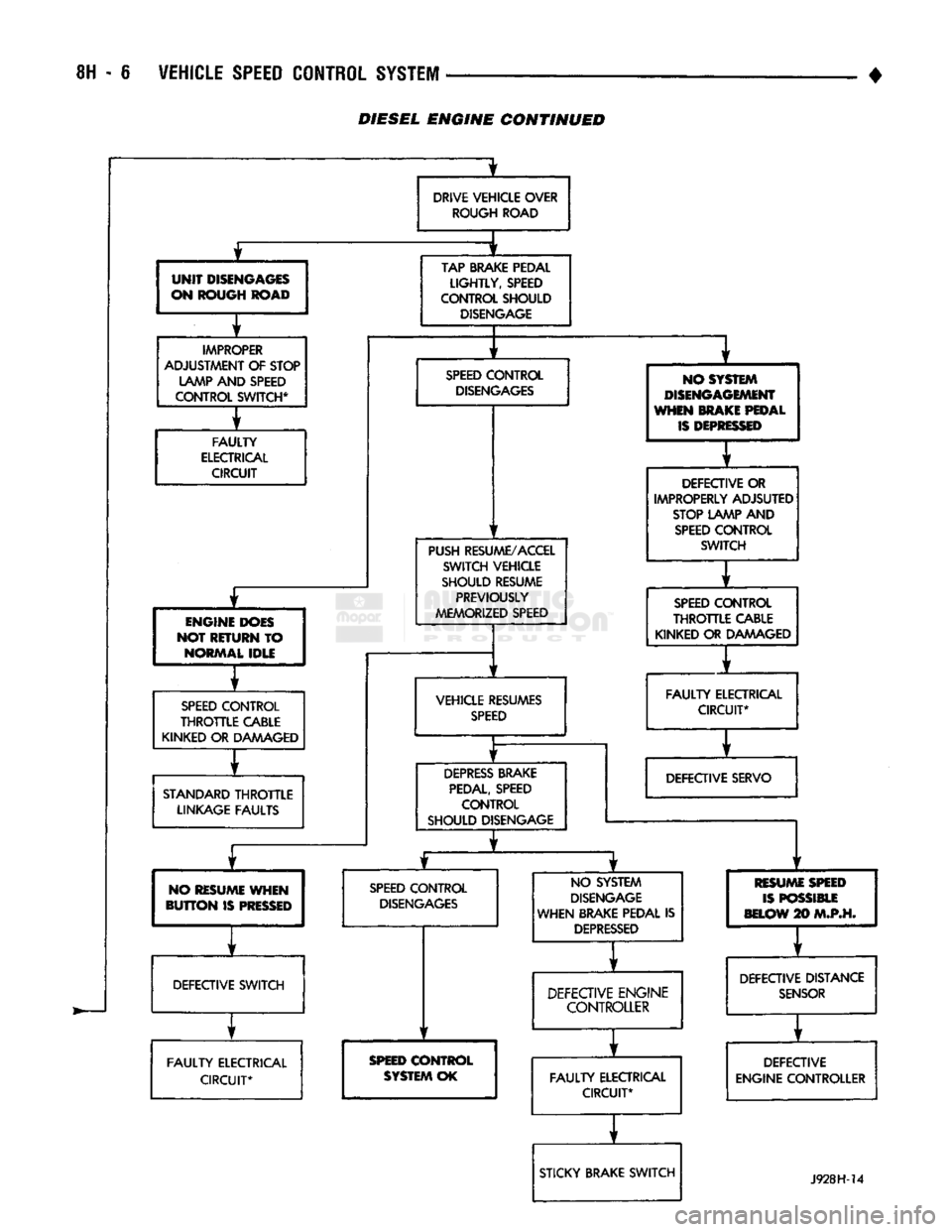
control wire harness is properly connected to all con nectors. Refer to Diagnosis Chart.
ROAD
TEST
Road test vehicle to verify reports of speed control
system malfunction. The road test should include at
tention to the speedometer. Speedometer operation should be smooth and without flutter at all speeds. Flutter in the speedometer indicates a problem
which might cause surging in the speed control sys
tem. The cause of any speedometer deficiencies should be corrected before proceeding.
INOPERATIVE SYSTEM
If road test verifies a system problem and the
speedometer operates properly, check for:
• loose electrical and vacuum connections at the
servo.
• check for correct installation of the vacuum check
valve in the hose from servo to vacuum source (Gas
Engine Only). The word VAC on the valve must
point toward the vacuum source. • corrosion that should be removed from electrical
terminals and a light coating of Mopar Multi-Pur
pose Grease, or equivalent, applied. • secure attachment of both ends of speed control ca
ble.
CHECKING
FOR DIAGNOSTIC TROUBLE CODE
(1) When trying to verify a speed control system
electrical problem, use a DRB II Scan Tool to find
the cause. Refer to Powertrain Diagnostic Procedures manual. If the DRBII is not available, the Diagnostic Trou
ble Code (DTC) may be determined with the follow ing method: (a) With key inserted in ignition switch, cycle
switch to ON position 3 times. On third cycle, leave
switch in ON position. (b) After switch has been cycled 3 times, observe
Malfunction Indicator Lamp (CHECK ENGINE) on instrument cluster. If a DTC is present, the code
page
Speed
Control
Cable Attachment—Servo
10
Stop Lamp Switch Test
9
Vacuum Supply Test
....................... 9
Vehicle Speed
Control
Switch Test
. 9
Vehicle Speed
Control
System
Electrical
Tests
... 7
Vehicle Speed Sensor Test
7
will be displayed in a series of flashes representing
digits.
Three flashes in rapid succession, a slight
pause, then 4 flashes in rapid succession would in dicate DTC 34.
(2) If a DTC 34 is observed, perform the tests in
the sections Electrical Tests at Servo and Electrical
Tests at Powertrain Control Module.
If a DTC 15 is observed, perform the test for a
faulty Vehicle Speed Sensor.
(3) If a fault code 11 is observed (Diesel only), per
form the test for a faulty engine speed sensor. Refer
to the Powertrain Diagnostics Procedures Manual.
(4) Correct any problems found when performing
these tests and recheck for DTC if changes were made.
VEHICLE SPEED SENSOR TEST
For testing of the Vehicle Speed Sensor and related
components refer to the Powertrain Diagnostic Proce
dures manual.
VEHICLE SPEED CONTROL SYSTEM ELECTRICAL
TESTS
Vehicle speed control systems may be tested using
two different methods. One involves the use of the DRBII Scan Tool. If this test method is desired,
please refer to the Powertrain Diagnostic Procedures manual. The other test method uses a voltmeter. The volt
meter method is described in the following tests.
If any information is needed concerning wiring, re
fer to Group 8W - Wiring Diagrams.
CAUTION:
When test probing
for
voltage
or
continuity
at
electrical
connectors, care must
be
taken
not
to
damage connector, terminals,
or
seals.
If
these components
are
damaged,
intermittent
or
complete system
failure
may
occur.
ELECTRICAL
TESTS
AT
SERVO
(1) Turn ignition switch to ON position.
(2) Push speed control switch to ON position.
(3) Connect the negative lead of a voltmeter to a
good chassis ground near the servo.
Page 423 of 1502
8H - 8
VEHICLE SPEED CONTROL SYSTEM
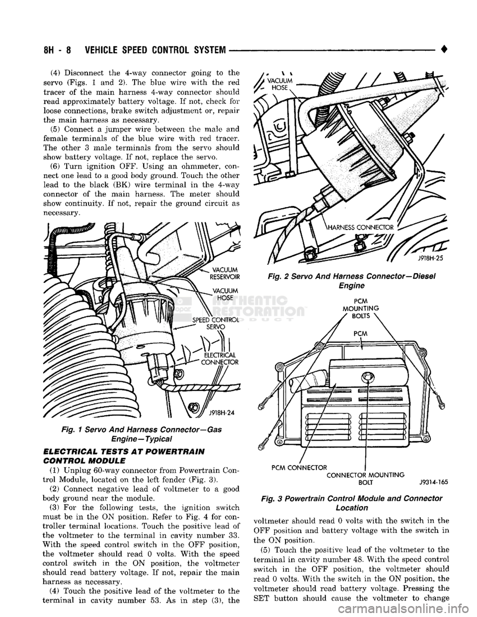
• (4) Disconnect the 4-way connector going to the
servo (Figs. 1 and 2), The blue wire with the red
tracer of the main harness 4-way connector should
read approximately battery voltage. If not, check for loose connections, brake switch adjustment or, repair
the main harness as necessary.
(5) Connect a jumper wire between the male and
female terminals of the blue wire with red tracer.
The other 3 male terminals from the servo should show battery voltage. If not, replace the servo. (6) Turn ignition OFF. Using an ohmmeter, con
nect one lead to a good body ground. Touch the other
lead to the black (BK) wire terminal in the 4-way
connector of the main harness. The meter should
show continuity. If not, repair the ground circuit as
necessary. A
VACUUM
y~
HOSE
J918H-24
Fig.
1 Servo And Harness Connector—Gas
Engine—Typical
ELECTRICAL TESTS AT POWERTRAIN CONTROL MODULE
(1) Unplug 60-way connector from Powertrain Con
trol Module, located on the left fender (Fig. 3).
(2) Connect negative lead of voltmeter to a good
body ground near the module. (3) For the following tests, the ignition switch
must be in the ON position. Refer to Fig. 4 for con
troller terminal locations. Touch the positive lead of
the voltmeter to the terminal in cavity number 33.
With the speed control switch in the OFF position,
the voltmeter should read 0 volts. With the speed
control switch in the ON position, the voltmeter should read battery voltage. If not, repair the main
harness as necessary.
(4) Touch the positive lead of the voltmeter to the
terminal in cavity number 53. As in step (3), the J918H-25
Fig. 2 Servo And Harness Connector—Diesel Engine PCM
MOUNTING
BOLTS
PCM CONNECTOR CONNECTOR MOUNTING BOLT
J9314-165
Fig.
3 Powertrain Control
Module
and
Connector
Location
voltmeter should read 0 volts with the switch in the OFF position and battery voltage with the switch in
the ON position. (5) Touch the positive lead of the voltmeter to the
terminal in cavity number 48. With the speed control switch in the OFF position, the voltmeter should
read 0 volts. With the switch in the ON position, the voltmeter should read battery voltage. Pressing the SET button should cause the voltmeter to change
Page 424 of 1502
![DODGE TRUCK 1993 Service Repair Manual
VEHICLE
SPEED
CONTROL SYSTEM
8H - 9
rain
oooooooooo
1 10,
.oooooooooo
\21 30
„. \£] 50 x
OOOOOOOOOO OOOOOOOOOO^
11
20
OOOOOOOOOO
51
31 1 6ooooooooo60y/ Tratr
TJKT
RR8HC DODGE TRUCK 1993 Service Repair Manual
VEHICLE
SPEED
CONTROL SYSTEM
8H - 9
rain
oooooooooo
1 10,
.oooooooooo
\21 30
„. \£] 50 x
OOOOOOOOOO OOOOOOOOOO^
11
20
OOOOOOOOOO
51
31 1 6ooooooooo60y/ Tratr
TJKT
RR8HC](/img/12/56922/w960_56922-423.png)
VEHICLE
SPEED
CONTROL SYSTEM
8H - 9
rain
oooooooooo
1 10,
.oooooooooo
\21 30
„. \£] 50 x
OOOOOOOOOO OOOOOOOOOO^
11
20
OOOOOOOOOO
51
31 1 6ooooooooo60y/ Tratr
TJKT
RR8HC7
Fig.
4 Powertrain Control Module 60-Way Connector
Shown from Terminal End
from battery voltage to 0 volts for as long as the switch is held. If not, perform the speed control
switch test. If the switch is not at fault, then check
the main harness and repair as necessary.
(6) Touch the positive lead of the voltmeter to the
terminal in cavity number 50. The voltmeter should read 0 volts with the speed control switch in either
the OFF or ON position. With switch in either RE SUME or SET position, the voltmeter should read
battery voltage. If not, perform the speed control switch test. If the switch is not at fault, then check
the main harness and repair as necessary.
(7) Touch the positive lead of the voltmeter to the
terminal in cavity number 49. The voltmeter should read 0 volts with the switch in the OFF position.
With the switch in the ON position, the voltmeter should read battery voltage. The voltmeter will con
tinue to read battery voltage when either the SET or
RESUME switch is pressed. If not, perform the speed control switch test. If the switch is not at fault, then
check the main harness and repair as necessary . (8) Turn key OFF. Using an ohmmeter, connect
one lead to a good body ground and touch the other
lead to the terminal in cavity number 29. With the
brake pedal released, the meter should show continu ity. When the pedal is depressed, the meter should
show open circuit.
VEHICLE
SPEED
CONTROL SWITCH TEST
To check the switch, remove the switch from its
mounting position. Use an ohmmeter and refer to the
Switch Continuity Chart to determine if continuity is
correct. If there is no continuity at any one of the
switch positions, replace the switch.
STOP
LAMP SWITCH TEST
(1) Disconnect connector at stop lamp switch. Us
ing an ohmmeter, continuity may be checked at
switch side of connector as follows (Fig. 5): (a) With brake pedal released, there should be:
• continuity between black (BK) and white with
pink tracer (WT/PK) wires
• continuity between yellow with red tracer (YL/RD) and dark blue with red tracer (DB/RD) wires
• No continuity between pink (PK) and white (WT)
wires.
SPEED CONTROL SWITCH CONTINUITY
CHART
CONNECTOR
TERMINAL
END
JE
El
SWITCH
SPEED
CONTROL
SWITCH
CONTINUITY
SWITCH!
rea?!®^
CONTINUITY
BETWEEN
OFF PIN 1
AND PIN 4
ON PIN
1 AND PIN 4
PIN 1
AND PIN 2
PIN
2 AND PIN 4
ON
AND
SET PIN
1
AN D
PIN 2
ON
AND
RESUME PIN
1 AND PIN 3
J928H-4
(b) With brake pedal depressed, there should be:
• continuity between pink (PK) and white (WT)
wires.
• No continuity between black (BK) and white with
pink tracer (WT/PK) wires.
• No continuity between yellow with red tracer (YL/
RD) and dark blue with red tracer (DB/RD) wires. (2) If the above results are not obtained, the stop
lamp switch is defective or out of adjustment.
Stop lamp switch adjustment is detailed in Group 5 -
Brakes.
VACUUM SUPPLY TEST
(1) Disconnect vacuum hose at the servo and in
stall a vacuum gauge in the hose (Fig. 6). (2) Start engine and observe gauge at idle. Vac
uum gauge should read at least ten inches of mer
cury. (3) If vacuum does not meet this requirement,
check for vacuum leaks or poor engine performance.
SPEED
CONTROL
CABLE
ADJUSTMENT-DIESEL
ENGINE
(1) The gap between the end of the slot on the ca
ble and the bellcrank pin must be as small as possi
ble (0 to 1mm) without moving the throttle. If gap is not correct, remove adjustment clip. Push protective
Page 425 of 1502
8H
- 10
VEHICLE
SPEED
CONTROL
SYSTEM
•
18PK ADJUSTMENT CLIP PULLED
OUT
OF
SLOT
18WT
STOP LAMP
SWITCH
WITH
SPEED
CONTROL
J938H-9
Fig.
5
Stop
Lamp
Switch
Connector
Fig.
6
Vacuum
Gauge
Test
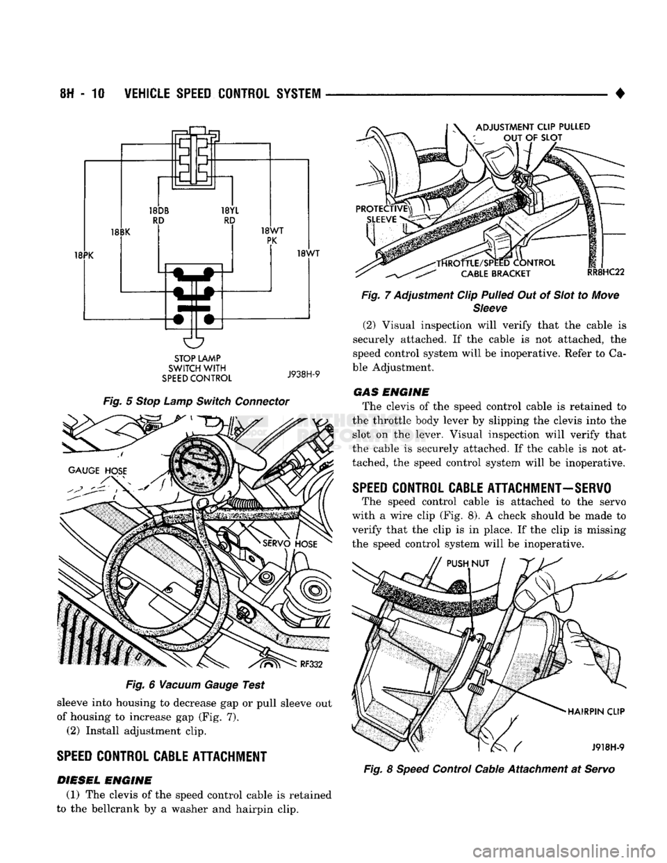
sleeve into housing to decrease gap or pull sleeve out
of housing to increase gap (Fig. 7). (2) Install adjustment clip.
SPEED
CONTROL CABLE ATTACHMENT
DIESEL
ENGINE
(1) The clevis of the speed control cable is retained
to the bellcrank by a washer and hairpin clip.
-TfiROTTLE/SPEED CONTROL
CABLE
BRACKET
RR8HC22
Fig.
7 Adjustment Clip
Pulled
Out of
Slot
to
Move
Sleeve
(2) Visual inspection will verify that the cable is
securely attached. If the cable is not attached, the
speed control system will be inoperative. Refer to Ca
ble Adjustment. GAS ENGINE
The clevis of the speed control cable is retained to
the throttle body lever by slipping the clevis into the slot on the lever. Visual inspection will verify that
the cable is securely attached. If the cable is not at
tached, the speed control system will be inoperative.
SPEED
CONTROL CABLE ATTACHMENT-SERVO
The speed control cable is attached to the servo
with a wire clip (Fig. 8). A check should be made to verify that the clip is in place. If the clip is missing
the speed control system will be inoperative.
HAIRPIN CLIP
/ J918H-9
Fig.
8
Speed
Control Cable Attachment at
Servo
Page 426 of 1502
•
VEHICLE
SPEED
CONTROL SYSTEM
8H - 11
SERVICE
PROCEDURES
INDEX
page
Servo
Throttle
Cable Assembly—Diesel Engine
. . 12
Servo
Throttle
Cable Assembly—Gas Engine
... 11
Servo
Unit
11
Speed
Control
Switch Replacement
12
page
Speed
Control
Vacuum Reservoir Replacement—Gas Engine
12
Vacuum Pump—Diesel Engine
. 12
SERVO
UNIT
REMOVAL
(1) Disconnect vacuum hose at servo.
(2)
Disconnect electrical connector at servo.
(3)
Remove 2 nuts from servo mounting bracket.
(4)
Pull servo away from mounting bracket.
(5)
Remove and discard push nuts on servo studs.
(6)
Pull speed control cable away from servo to ex
pose cable retaining clip.
(7) Remove clip attaching cable to servo.
INSTALLATION
(1) Block throttle to full open position (gas engine),
pivot bellcrank full rearward (diesel engine), and align hole in cable sleeve with hole in servo pin. In
stall retaining clip.
(2)
Insert servo studs through holes in the cable.
(3)
Install new push nuts on the servo studs.
(4)
Insert servo studs through holes in servo
mounting bracket. One stud mounts reservoir.
(5)
Install the 2 attaching nuts and tighten to 6
N*m (50 in. lbs.).
(6)
Connect vacuum hose to servo. (7) Connect the electrical connector to servo termi
nals.
SERVO
THROTTLE CABLE ASSEMBLY-GAS
ENGINE
REMOVAL
(1) Remove air cleaner.
(2)
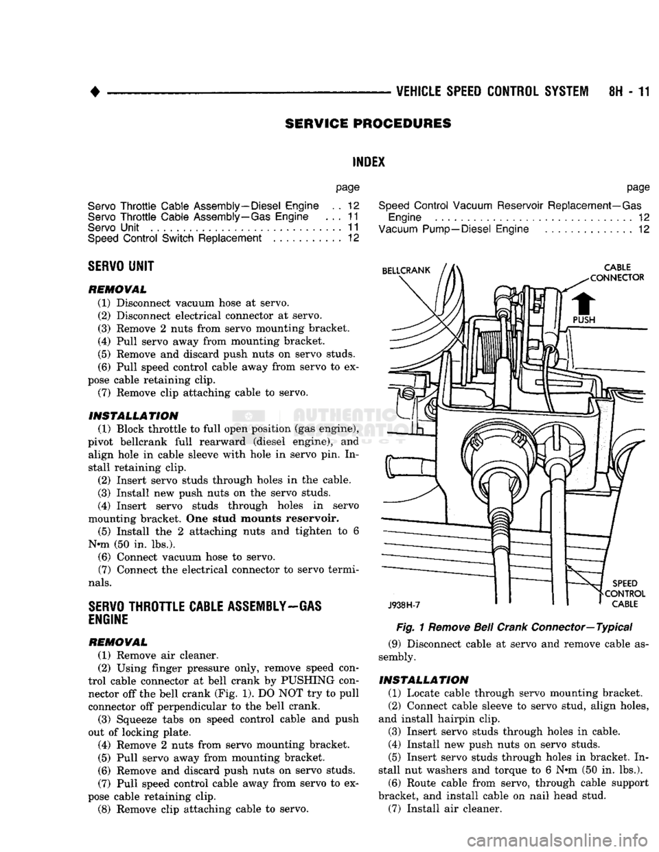
Using finger pressure only, remove speed con
trol cable connector at bell crank by PUSHING con nector off the bell crank (Fig. 1). DO NOT try to pull
connector off perpendicular to the bell crank.
(3)
Squeeze tabs on speed control cable and push
out of locking plate.
(4)
Remove 2 nuts from servo mounting bracket.
(5)
Pull servo away from mounting bracket.
(6)
Remove and discard push nuts on servo studs.
(7) Pull speed control cable away from servo to ex
pose cable retaining clip.
(8)
Remove clip attaching cable to servo.
Fig.
1
Remove
Bell
Crank
Connector—
Typical
(9) Disconnect cable at servo and remove cable as
sembly.
INSTALLATION
(1) Locate cable through servo mounting bracket.
(2)
Connect cable sleeve to servo stud, align holes,
and install hairpin clip.
(3)
Insert servo studs through holes in cable.
(4)
Install new push nuts on servo studs.
(5)
Insert servo studs through holes in bracket. In
stall nut washers and torque to 6 Nnn (50 in. lbs.).
(6)
Route cable from servo, through cable support
bracket, and install cable on nail head stud.
(7) Install air cleaner.
Page 427 of 1502
8H
- 12
VEHICLE SPEED CONTROL SYSTEM
•
SERVO
THROTTLE CABLE ASSEMBLY—DIESEL
ENGINE
REMOVAL (1) Remove hairpin clip and washer retaining ca
bles on bellcrank. Remove servo throttle cable from bellcrank.
(2) Remove servo throttle cable from cable support
bracket.
(3) Remove 2 nuts from servo mounting bracket.
(4) Pull servo away from mounting bracket.
(5) Remove and discard push nuts on servo studs. (6) Pull speed control cable away from servo to ex
pose cable retaining clip. (7) Remove clip attaching cable to servo.
(8) Disconnect cable at servo and remove cable as
sembly.
INSTALLATION (1) Locate cable through servo mounting bracket.
(2) Connect cable sleeve to servo stud, align holes,
and install hairpin clip.
(3) Insert servo studs through holes in cable.
(4) Install new push nuts on servo studs.
(5) Insert servo studs through holes in bracket. In
stall nut washers and torque to 6 N*m (50 in. lbs.).
(6) Route cable from servo, to cable support
bracket, (7) Install cable end on bellcrank rod.
(8) Adjust cable as described under speed control
cable adjustment. (9) Install washer and hairpin clip on end of bell
crank rod.
SPEED
CONTROL
SWITCH
REPLACEMENT
(1) Disconnect negative cable from battery.
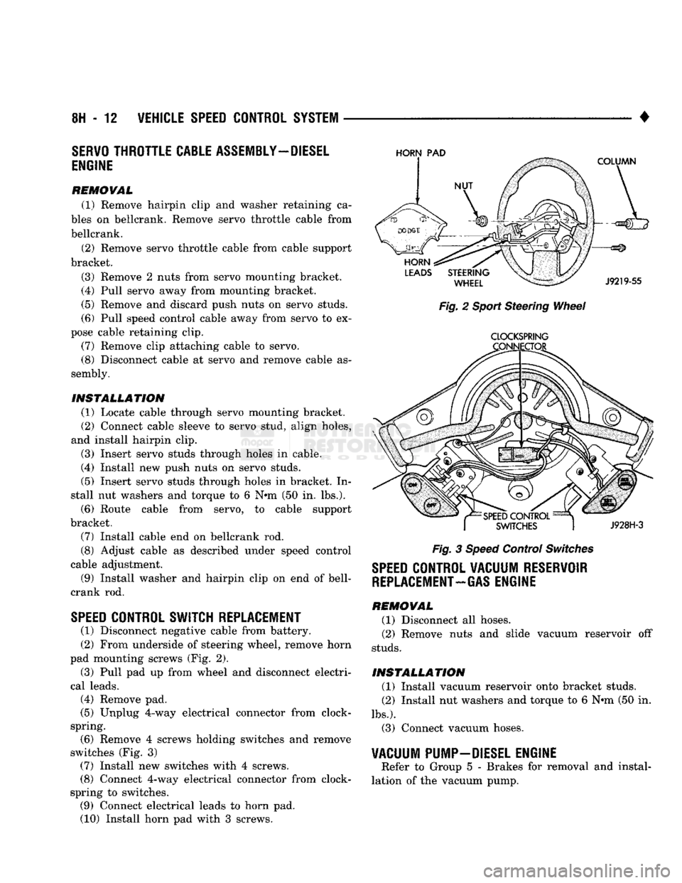
(2) From underside of steering wheel, remove horn
pad mounting screws (Fig. 2).
(3) Pull pad up from wheel and disconnect electri
cal leads.
(4) Remove pad.
(5) Unplug 4-way electrical connector from clock-
spring. (6) Remove 4 screws holding switches and remove
switches (Fig. 3) (7) Install new switches with 4 screws.
(8) Connect 4-way electrical connector from clock-
spring to switches. (9) Connect electrical leads to horn pad.
(10) Install horn pad with 3 screws.
HORN
PAD
Fig. 2 Sport Steering Wheel
CLOCKSPRING
Fig. 3 Speed Control Switches
SPEED
CONTROL VACUUM RESERVOIR
REPLACEMENT-GAS
ENGINE
REMOVAL (1) Disconnect all hoses.
(2) Remove nuts and slide vacuum reservoir off
studs.
INSTALLATION (1) Install vacuum reservoir onto bracket studs.
(2) Install nut washers and torque to 6 Nrn (50 in.
lbs.).
(3) Connect vacuum hoses.
VACUUM PUMP-DIESEL ENGINE
Refer to Group 5 - Brakes for removal and instal
lation of the vacuum pump.
Page 428 of 1502
•
TURN SIGNALS
AND
HAZARD WARNING FLASHER
8J - 1
CONTENTS
page page
GENERAL
INFORMATION
1
MULTIFUNCTION SWITCH TESTING MULTIFUNCTION SWITCH SERVICE PROCEDURES
2
PROCEDURES
3
GENERAL
INFORMATION
TURN SIGNALS
DESCRIPTION With
the
ignition
key ON and the
multi-function
lever
in its UP or
DOWN position, current flows
through
the:
• turn signal flasher canister • Turn/Hazard switch
• turn indicator lamp
• front
and
rear bulbs. The selected turn signal indicator with front
and
rear turn signal bulbs will flash.
DIAGNOSIS High generator output voltage
can
burn
out
lamps rapidly. (1) Remove
and
inspect fuse
in
cavity
#9 of
fuse
block. Replace
if
necessary.
The
fuse block
is
behind
the lower instrument panel cover under steering wheel. (2) Turn
key to
ACCY. There should
be
battery
voltage
at the
fuse side
of the
turn signal flasher (bottom terminal).
If
not,
repair open circuit
in
wir
ing between fuse
and
flasher.
(3) Replace Turn Flasher with
2
lamp
12
volt rated
flasher that
is
know
to be
good.
The
lamps should
flash. If
not,
replace with original flasher
and
go to
next step.
(4) Measure voltage
at the
Turn/Hazard switch
connector cavity
#17.
Meter should read battery volt
age.
If
OK,
replace Turn/Hazard switch assembly.
If
not, repair open circuit
in
wiring between flasher
and Turn/Hazard switch connector.
HAZARD WARNING SYSTEM
DESCRIPTION
With
the
hazard switch
OUT,
current flows
through
the
• hazard flasher canister
• hazard switch
•
two
front turn signal bulbs
•
two
rear turn signal bulbs
• both indicator bulbs.
All
of the
turn lamps
and
both indicators will
flash.
DIAGNOSIS Hazard switch
in
ON.
The
park
and
stop lamps
should light.
If
not
replace
the 20
amp
fuse
in
fuse
block cavity
#13.
(1) Measure voltage
at
the
fuse side
of
the
flasher
(side terminal). Meter should read battery voltage.
If
not, repair open circuit
in
wiring
to
fuse. (2) Replace Hazard flasher with known good
flasher. Lamps should flash.
If
not, replace with orig
inal flasher
and go
to
next step.
(3) Measure voltage
at the
Turn/Hazard switch
connector cavity #13. Meter should read battery volt
age.
If
not,
repair open circuit
in
wiring
to
hazard
flasher.
TURN
SIGNAL AND HAZARD
WARNING
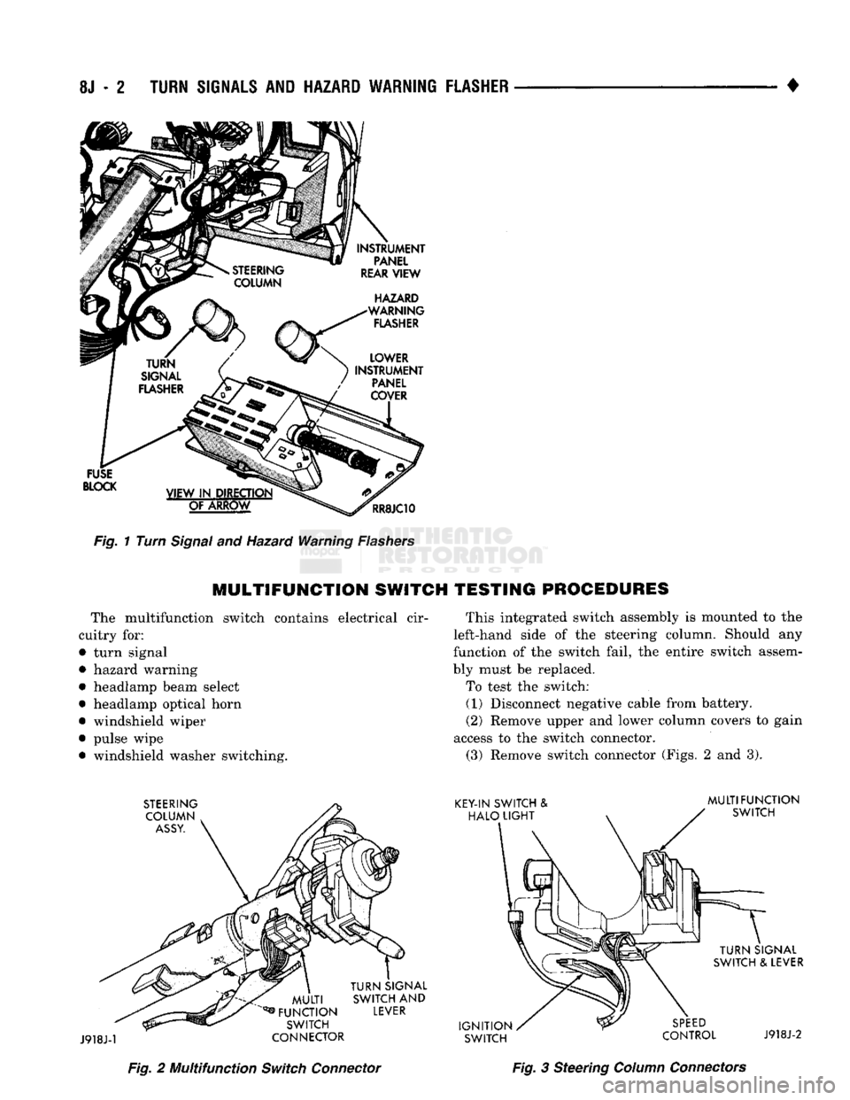
FLASHER
LOCATION
The turn signal
and
hazard warning flasher
are
both located
on the
fuse block (Fig.
1). The
fuse block is
on the
lower instrument panel cover under
the
steering column.
TURN SIGNALS AND HAZARD WARNING
FLASHER
Page 429 of 1502
8J
- 2
TURN SIGNALS AND HAZARD WARNING FLASHER
•
FUSE
BLOCK
INSTRUMENT
PANEL
REAR
VIEW
HAZARD
WARNING
FLASHER
VIEW
IN DIRECTION OF
ARROW
RR8JC10
Fig.
1 Turn
Signal
and Hazard Warning
Flashers
MULTIFUNCTION
SWITCH TESTING PROCEDURES
The multifunction switch contains electrical cir
cuitry for:
• turn signal
• hazard warning
• headlamp beam select
• headlamp optical horn
• windshield wiper
• pulse wipe • windshield washer switching. This integrated switch assembly is mounted to the
left-hand side of the steering column. Should any
function of the switch fail, the entire switch assem
bly must be replaced.
To test the switch: (1) Disconnect negative cable from battery.
(2) Remove upper and lower column covers to gain
access to the switch connector. (3) Remove switch connector (Figs. 2 and 3).
Fig.
2 Multifunction
Switch
Connector
Fig.
3 Steering
Column
Connectors
Page 430 of 1502
•
TURN
SIGNALS
AND
HAZARD WARNING FLASHER
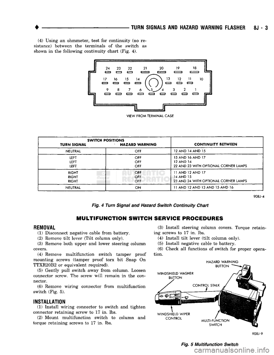
8J - 3 (4) Using an ohmmeter, test for continuity (no re
sistance) between the terminals of the switdh as shown in the following continuity chart (Pig. 4).
VIEW
FROM TERMINAL CASE
SWITCH POSITIONS
TURN
SIGNAL HAZARD WARNING
CONTINUITY
BETWEEN
NEUTRAL
OFF 12
AND 14 AND 15
LEFT
LEFT
LEFT
OFF
OFF
OFF 15
AND 16 AND 17
12
AND 14
22
AND 23 WITH OPTIONAL CORNER LAMPS
RIGHT
RIGHT
RIGHT
OFF
OFF
OFF 11
AND 12 AND 17
14
AND 15
23
AND 24 WITH OPTIONAL CORNER LAMPS
NEUTRAL
ON 11
AND 12 AND 13 AND 15 AND 16
908J-4
Fig.
4 Turn
Signal
and Hazard Switch Continuity Chart
MULTIFUNCTION SWITCH SERVICE PROCEDURES
REMOVAL
(1) Disconnect negative cable from battery.
(2) Remove tilt lever (Tilt column only).
(3) Remove both upper and lower steering column
covers. (4) Remove multifunction switch tamper proof
mounting screws (tamper proof torx bit Snap On
TTXR20B2 or equivalent required). (5) Gently pull switch away from column. Loosen
connector screw. The screw will remain in the con
nector. (6) Remove wiring connector from multifunction
switch (Fig. 5).
INSTALLATION
(1) Install wiring connector to switch and tighten
connector retaining screw to 17 in. lbs. (2) Mount multifunction switch to column and
torque retaining screws to 17 in. lbs. (3) Install steering column covers. Torque retain
ing screws to 17 in. lbs. (4) Install tilt lever (tilt column only).
(5) Install negative cable to battery.
(6) Check all functions of switch for proper opera
tion.
HAZARD
WARNING
908J-9
Fig.
5 Muitifunction Switch