DODGE TRUCK 1993 Service Repair Manual
Manufacturer: DODGE, Model Year: 1993, Model line: TRUCK, Model: DODGE TRUCK 1993Pages: 1502, PDF Size: 80.97 MB
Page 951 of 1502
16 - 6
PROPELLER
SHAFTS
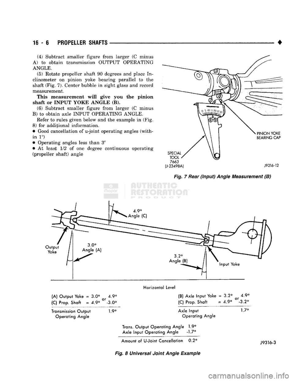
• (4) Subtract smaller figure from larger (C minus
A) to obtain transmission OUTPUT OPERATING
ANGLE. (5) Rotate propeller shaft 90 degrees and place In
clinometer on pinion yoke bearing parallel to the
shaft (Fig. 7). Center bubble in sight glass and record
measurement.
This measurement will give you the pinion
shaft or INPUT YOKE ANGLE (B). (6) Subtract smaller figure from larger (C minus
B) to obtain axle INPUT OPERATING ANGLE. Refer to rules given below and the example in (Fig.
8) for additional information.
• Good cancellation of u-joint operating angles (with
in 1°)
• Operating angles less than 3°
• At least 1/2 of one degree continuous operating (propeller shaft) angle
7663
(J-23498A)
J9216-12
Fig.
7 Rear
(input)
Angle
Measurement (B)
Horizontal Level
(A) Output Yoke = 3.0° 4.9° (B) Axle Input Yoke = 3.2° Qr 4.9°
(C) Prop. Shaft = 4.9° °r-3.0° (C) Prop. Shaft = 4.9° -3.2°
Transmission Output 1.9° Axle Input 1.7° Operating Angle Operating Angle
Trans.
Output Operating Angle 1.9°
Axle Input Operating Angle -1.7°
Amount of U-Joint Cancellation 0.2°
Fig.
8 Universal Joint
Angle
Example J9316-3
Page 952 of 1502
•
PROPELLER SHAFTS
16 - 7 ADJUSTMENT AT AXLE WITH LEAF SPRINGS
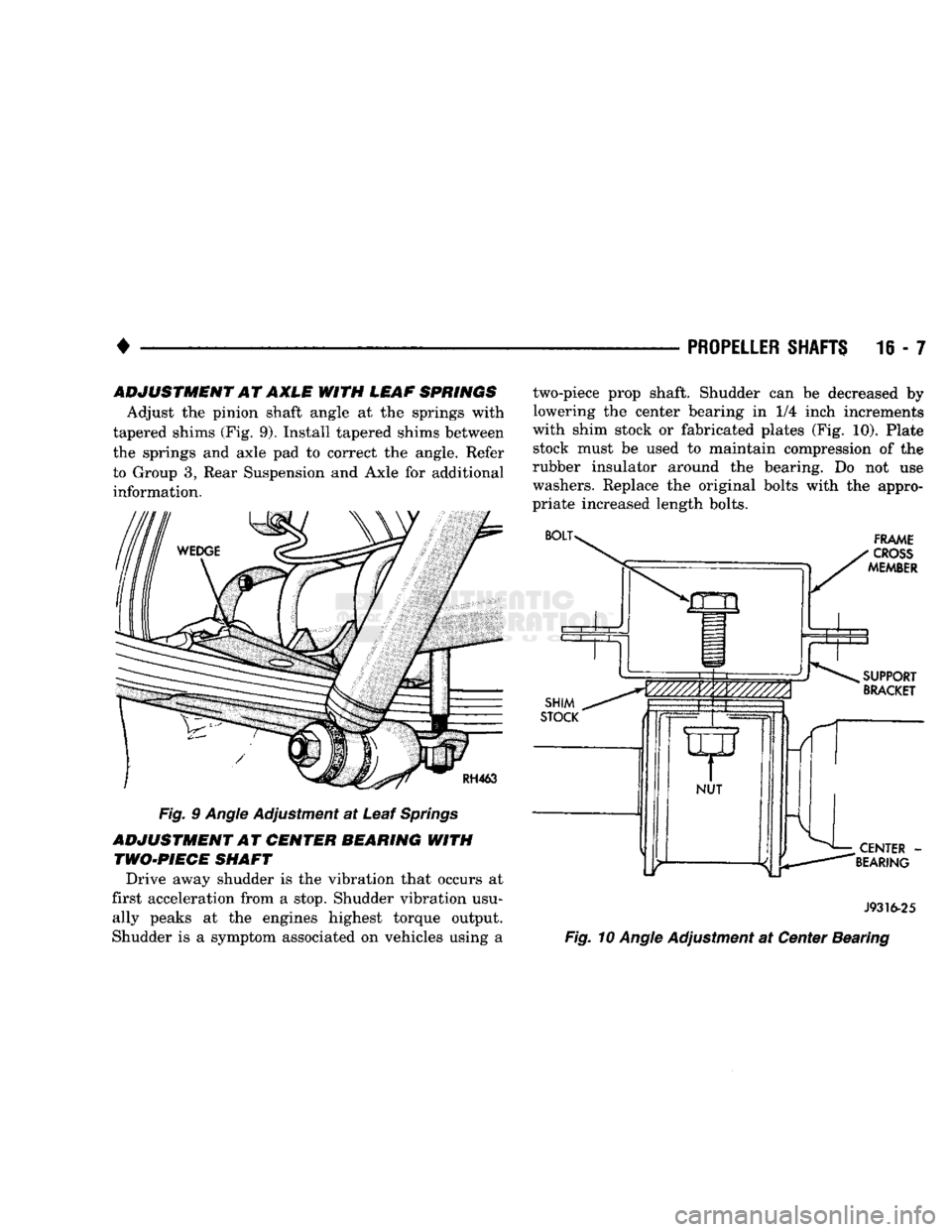
Adjust the pinion shaft angle at the springs with
tapered shims (Fig. 9). Install tapered shims between
the springs and axle pad to correct the angle. Refer to Group 3, Rear Suspension and Axle for additional information.
Fig. 9 Angle Adjustment at Leaf Springs
ADJUSTMENT AT CENTER BEARING WITH TWO-PIECE SHAFT
Drive away shudder is the vibration that occurs at
first acceleration from a stop. Shudder vibration usu ally peaks at the engines highest torque output.
Shudder is a symptom associated on vehicles using a two-piece prop shaft. Shudder can be decreased by
lowering the center bearing in 1/4 inch increments
with shim stock or fabricated plates (Fig. 10). Plate stock must be used to maintain compression of the
rubber insulator around the bearing. Do not use
washers. Replace the original bolts with the appro
priate increased length bolts.
J9316-25
Fig. 10 Angle Adjustment at Center Bearing
Page 953 of 1502
16-8
PROPELLER SHAFTS
•
PROPELLER SHAFT REPLACEMENT
PRECAUTIONS
Use exact replacement hardware for attaching the
propeller shafts. Exact replacement will ensure safe
operation. The specified torque must always be ap
plied when tightening the fasteners. Mark the propeller shaft yoke and axle or trans
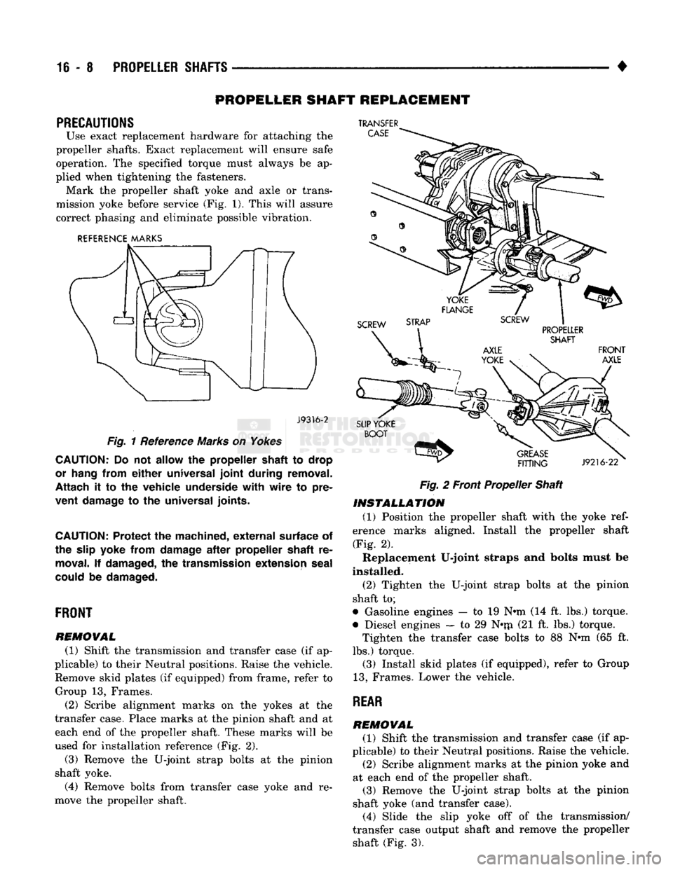
mission yoke before service (Fig. 1). This will assure correct phasing and eliminate possible vibration.
REFERENCE MARKS
J9316-2
Fig.
1 Reference Marks on
Yokes
CAUTION:
Do not
allow
the
propeller shaft
to
drop
or hang from
either
universal
joint
during removal.
Attach
it to the
vehicle underside
with
wire
to
pre
vent damage
to the
universal joints.
CAUTION:
Protect
the
machined,
external
surface
of
the slip
yoke
from damage
after
propeller shaft
re
moval.
If
damaged,
the
transmission extension seal
could
be
damaged.
FRONT
REMOVAL
(1) Shift the transmission and transfer case (if ap
plicable) to their Neutral positions. Raise the vehicle. Remove skid plates (if equipped) from frame, refer to Group 13, Frames. (2) Scribe alignment marks on the yokes at the
transfer case. Place marks at the pinion shaft and at each end of the propeller shaft. These marks will be
used for installation reference (Fig. 2). (3) Remove the U-joint strap bolts at the pinion
shaft yoke. (4) Remove bolts from transfer case yoke and re
move the propeller shaft.
TRANSFER
Fig.
2 Front Propeller Shaft
INSTALLATION
(1) Position the propeller shaft with the yoke
ref
erence marks aligned. Install the propeller shaft
(Fig. 2). Replacement U-joint straps and bolts must be
installed.
(2) Tighten the U-joint strap bolts at the pinion
shaft to;
• Gasoline engines — to 19 N*m (14 ft. lbs.) torque.
• Diesel engines — to 29 N*rri (21 ft. lbs.) torque. Tighten the transfer case bolts to 88 Nnn (65 ft.
lbs.) torque. (3) Install skid plates (if equipped), refer to Group
13,
Frames. Lower the vehicle.
REAR
REMOVAL
(1) Shift the transmission and transfer case (if ap
plicable) to their Neutral positions. Raise the vehicle. (2) Scribe alignment marks at the pinion yoke and
at each end of the propeller shaft.
(3) Remove the U-joint strap bolts at the pinion
shaft yoke (and transfer case). (4) Slide the slip yoke off of the transmission/
transfer case output shaft and remove the propeller shaft (Fig. 3).
Page 954 of 1502
•
PROPELLER
SHAFTS
16-9
SLIDING
SCREW
19 N-m
(14 ft-lbs).
CLAMP
J9216-6
Fig.
3 Rear Propeller Shaft
INSTALLATION
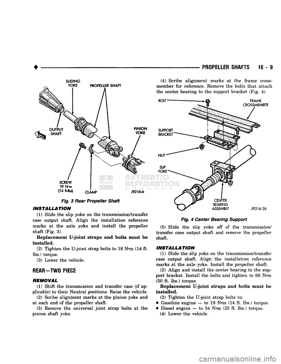
(1) Slide the slip yoke on the transmission/transfer
case output shaft. Align the installation reference
marks at the axle yoke and install the propeller shaft (Fig. 3). Replacement U-joint straps and bolts must be
installed. (2) Tighten the U-joint strap bolts to 19 Nnn (14 ft.
lbs.) torque. (3) Lower the vehicle.
REAR-TWO PIECE
REMOVAL
(1) Shift the transmission and transfer case (if ap
plicable) to their Neutral positions. Raise the vehicle.
(2) Scribe alignment marks at the pinion yoke and
at each end of the propeller shaft. (3) Remove the universal joint strap bolts at the
pinion shaft yoke. (4) Scribe alignment marks at the frame cross-
member for reference. Remove the bolts that attach
the center bearing to the support bracket (Fig. 4).
Fig.
4 Center Bearing
Support
(5) Slide the slip yoke off of the transmission/
transfer case output shaft and remove the propeller shaft.
INSTALLATION
(1) Slide the slip yoke on the transmission/transfer
case output shaft. Align the installation reference
marks at the axle yoke. Install the propeller shaft.
(2) Align and install the center bearing to the sup
port bracket. Install the bolts and tighten to 68 Nnn (50 ft. lbs.) torque.
Replacement U-joint straps and bolts must be
installed. (3) Tighten the U-joint strap bolts to;
• Gasoline engine — to 19 Nnn (14 ft. lbs.) torque.
• Diesel engine — to 34 Nnn (25 ft. lbs.) torque. (4) Lower the vehicle.
Page 955 of 1502
16-10 PROPELLER SHAFTS
•
UNIVERSAL
JOINT
REPLACEMENT
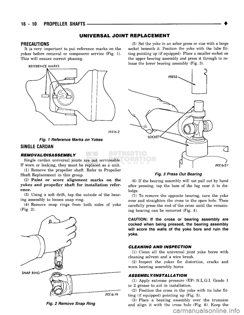
PRECAUTIONS
It
is
very important
to put
reference marks
on the
yokes before removal
or
component service (Fig.
1).
This will ensure correct phasing.
REFERENCE MARKS
J9316-2
Fig.
1 Reference Marks on
Yokes
SINGLE CARDAN
REMO
VAL/DISASSEMBL Y
Single cardan universal joints
are not
serviceable.
If worn
or
leaking, they must
be
replaced
as a
unit. (1) Remove
the
propeller shaft. Refer
to
Propeller
Shaft Replacement
in
this group.
(2) Paint
or
score alignment marks
on the
yokes
and
propeller shaft
for
installation refer
ence. (3) Using
a
soft drift,
tap the
outside
of
the bear
ing assembly
to
loosen snap ring.
(4) Remove snap rings from both sides
of
yoke
(Fig.
2).
(5) Set the yoke
in an
arbor press
or
vise with
a
large
socket beneath
it.
Position
the
yoke with
the
lube fit
ting pointing up (if equipped). Place
a
smaller socket on the upper bearing assembly and press
it
through
to
re
lease the lower bearing assembly (Fig.
3).
J9316-19
Fig.
2
Remove
Snap
Ring
J9316-2V
Fig.
3
Press
Out Bearing (6)
If
the bearing assembly will not pull out
by
hand
after pressing,
tap the
base
of
the
lug
near
it to
dis
lodge. (7)
To
remove
the
opposite bearing, turn
the
yoke
over
and
straighten
the
cross
in the
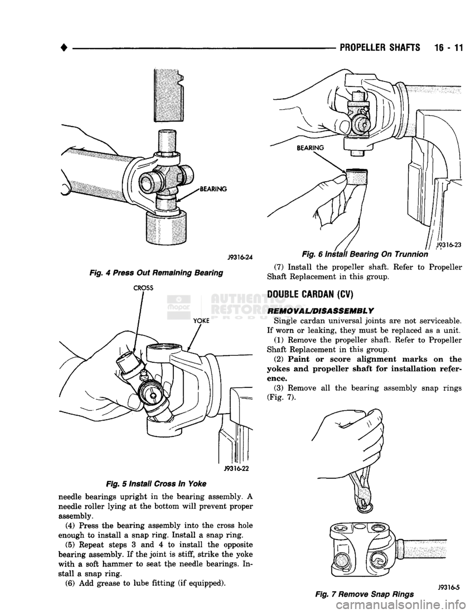
open hole. Then
carefully press the end
of
the cross until the remain
ing bearing can
be
removed (Fig.
4).
CAUTION:
If the
cross
or
bearing
assembly
are
cocked
when being
pressed,
the
bearing
assembly
will
score
the
walls
of the
yoke bore and ruin
the
yoke.
CLEANING
AND
INSPECTION
(1) Clean
all the
universal joint yoke bores with
cleaning solvent and
a
wire brush.
(2) Inspect
the
yokes
for
distortion, cracks
and
worn bearing assembly bores.
ASSEMBL
Y/INSTALLA
TION
(1) Apply extreme pressure (EP) N.L.G.I. Grade
1
or
2
grease
to aid in
installation.
(2) Position
the
cross
in the
yoke with
its
lube fit
ting
(if
equipped) pointing
up
(Fig.
5).
(3) Place
a
bearing assembly over
the
trunnion
and align
it
with
the
cross hole (Fig.
6).
Keep
the
Page 956 of 1502
•
BEARING J9316-24
Fig.
4
Press
Out
Remaining
Bearing
CROSS
J9316-22
Fig.
5 Install
Cross
In Yoke needle bearings upright in the bearing assembly. A
needle roller lying at the bottom will prevent proper assembly.
(4)
Press the bearing assembly into the cross hole
enough to install a snap ring. Install a snap ring.
(5)
Repeat steps 3 and 4 to install the opposite
bearing assembly. If the joint is
stiff,
strike the yoke
with a soft hammer to seat tjie needle bearings. In stall a snap ring.
(6) Add grease to lube fitting (if equipped).
PROPELLER
SHAFTS
16 - 11
(7) Install the propeller shaft. Refer to Propeller
Shaft Replacement in this group.
DOUBLE CARDAN
(CV)
REMOVAL/DISASSEMBL
Y
Single cardan universal joints are not serviceable.
If worn or leaking, they must be replaced as a unit. (1) Remove the propeller shaft. Refer to Propeller
Shaft Replacement in this group.
(2)
Paint or score alignment marks on the
yokes and propeller shaft for installation refer ence.
(3) Remove all the bearing assembly snap rings
(Fig. 7).
J9316-5
Fig.
7
Remove Snap Rings
Page 957 of 1502
16 - 12
PROPELLER
SHAFTS
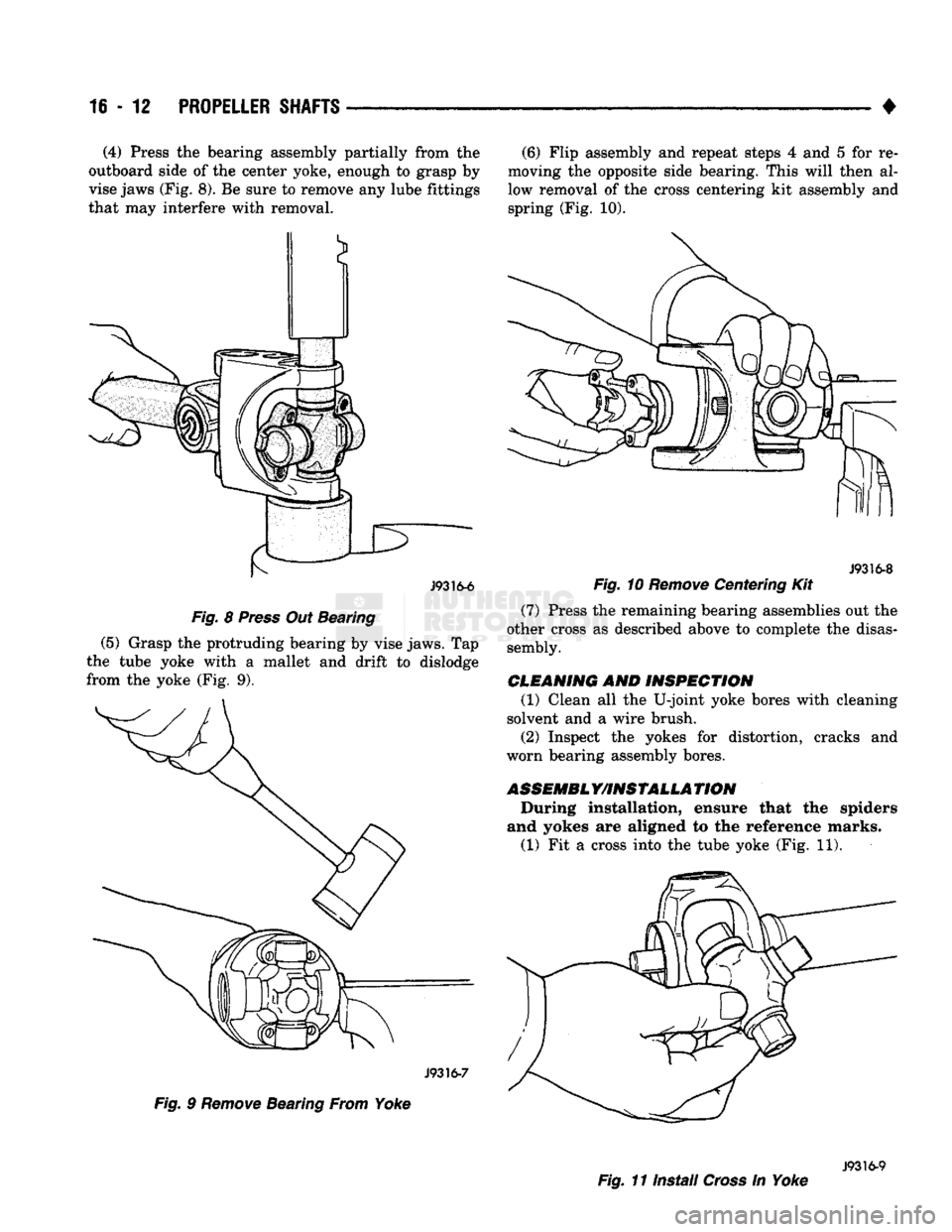
• (4) Press the bearing assembly partially from the
outboard side of the center yoke, enough to grasp by
vise jaws (Fig. 8). Be sure to remove any lube fittings
that may interfere with removal.
f—^ J9316-6
Fig.
8
Press
Out Bearing
(5) Grasp the protruding bearing by vise jaws. Tap
the tube yoke with a mallet and drift to dislodge
from the yoke (Fig. 9).
J9316-7
Fig.
9
Remove
Bearing From Yoke (6) Flip assembly and repeat steps 4 and 5 for re
moving the opposite side bearing. This will then al
low removal of the cross centering kit assembly and
spring (Fig. 10).
J9316-8
Fig.
10
Remove
Centering Kit
(7) Press the remaining bearing assemblies out the
other cross as described above to complete the disas sembly.
CLEANING AND INSPECTION (1) Clean all the U-joint yoke bores with cleaning
solvent and a wire brush.
(2) Inspect the yokes for distortion, cracks and
worn bearing assembly bores.
ASSEMBLY/INSTALLATION
During installation, ensure that the spiders
and yokes are aligned to the reference marks. (1) Fit a cross into the tube yoke (Fig. 11).
J9316-9
Fig.
11 Install
Cross
In Yoke
Page 958 of 1502
•
PROPELLER SHAFTS
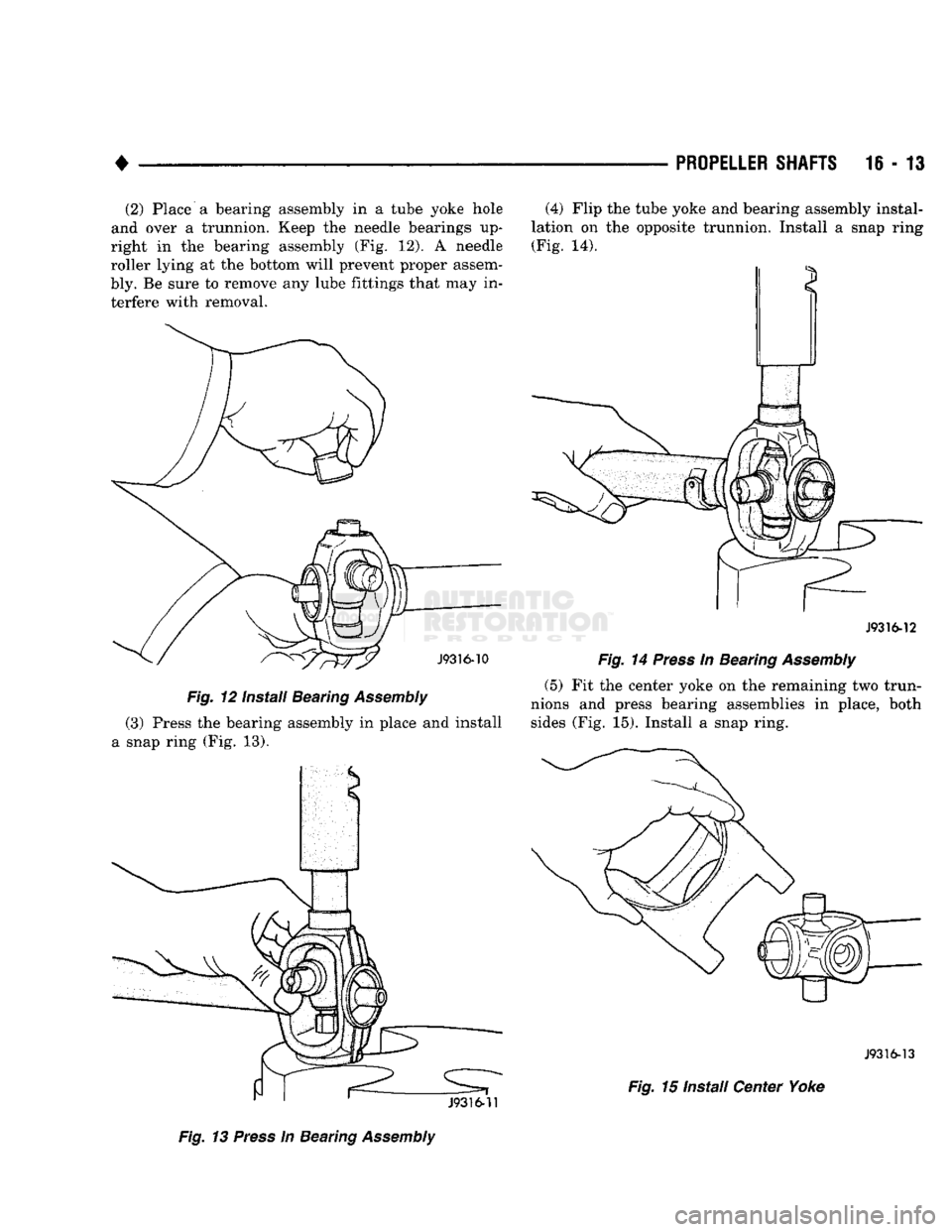
16 - 13 (2) Place a bearing assembly in a tube yoke hole
and over a trunnion. Keep the needle bearings up
right in the bearing assembly (Fig. 12). A needle
roller lying at the bottom will prevent proper assem
bly. Be sure to remove any lube fittings that may in terfere with removal.
Fig.
12 Install Bearing
Assembly
(3) Press the bearing assembly in place and install
a snap ring (Fig. 13).
Fig.
13
Press
in Bearing
Assembly
(4) Flip the tube yoke and bearing assembly instal
lation on the opposite trunnion. Install a snap ring (Fig. 14).
J9316-12
Fig.
14
Press
In Bearing
Assembly
(5) Fit the center yoke on the remaining two trun
nions and press bearing assemblies in place, both sides (Fig. 15). Install a snap ring.
J9316-13
Fig.
15 Install Center Yoke
Page 959 of 1502
16-14
PROPELLER
SHAFTS
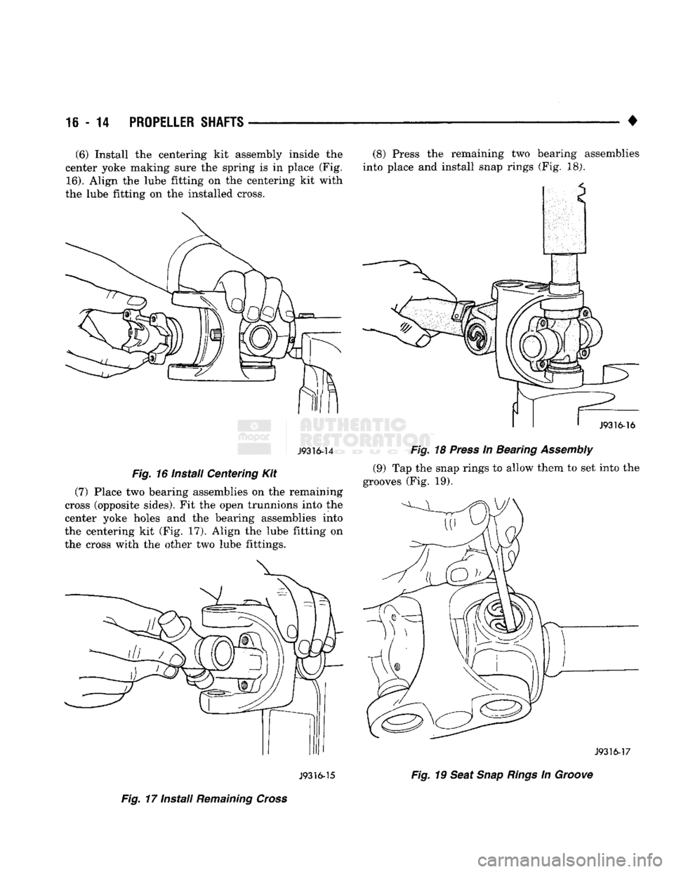
(6) Install the centering kit assembly inside the
center yoke making sure the spring is in place (Fig.
16).
Align the lube fitting on the centering kit with
the lube fitting on the installed cross.
J9316-14
Fig.
16 Instail Centering Kit
(7) Place two bearing assemblies on the remaining
cross (opposite sides). Fit the open trunnions into the
center yoke holes and the bearing assemblies into
the centering kit (Fig, 17). Align the lube fitting on the cross with the other two lube fittings. J9316-15
Fig.
17 Install
Remaining
Cross
(8) Press the remaining two bearing assemblies
into place and install snap rings (Fig. 18).
I
1
J9316-16
Fig.
18
Press
In Bearing
Assembly
(9) Tap the snap rings to allow them to set into the
grooves (Fig. 19).
J9316-17
Fig.
19
Seat
Snap
Rings
In
Groove
Page 960 of 1502
PROPELLER SHAFTS
16
- 15
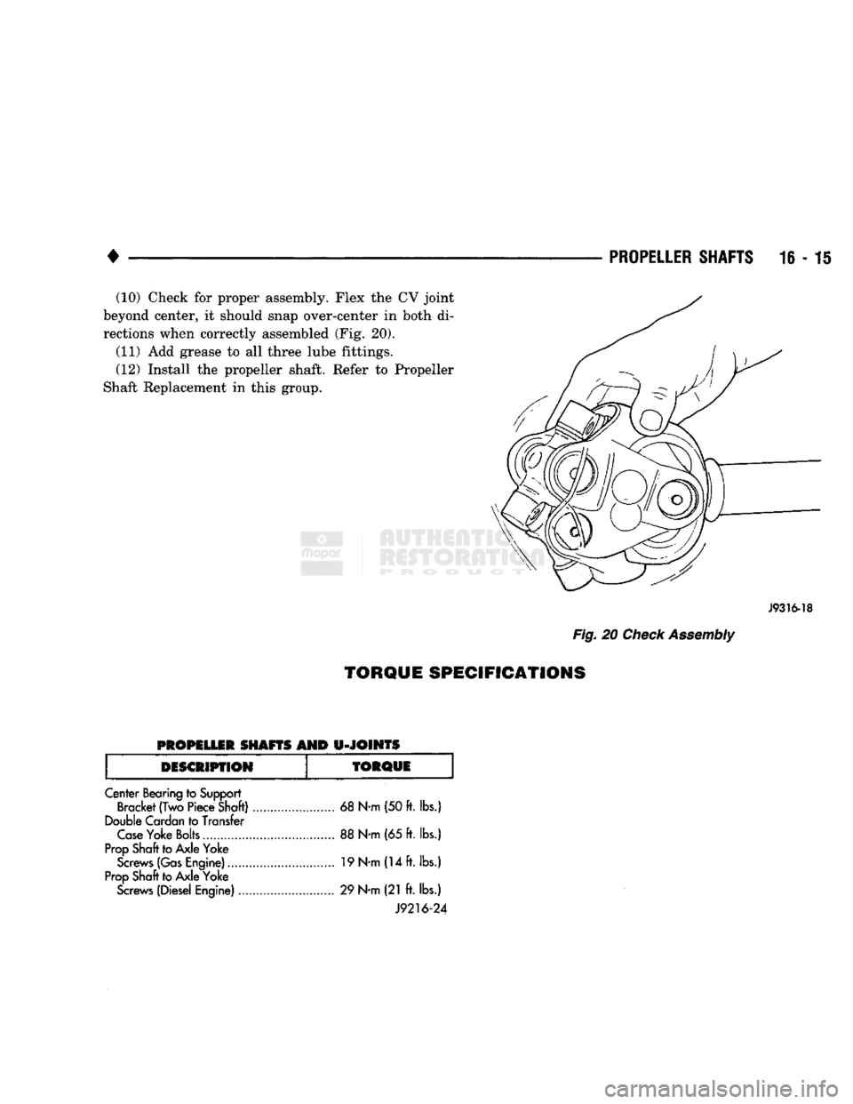
(10) Check
for
proper assembly. Flex
the CV
joint
beyond center,
it
should snap over-center
in
both
di
rections when correctly assembled
(Fig. 20).
(11)
Add
grease
to all
three lube fittings.
(12) Install
the
propeller shaft. Refer
to
Propeller
Shaft Replacement
in
this group.
J9316-18
Fig.
20
Check Assembly
TORQUE SPECIFICATIONS
PROPELLER
SHAFTS
AND
U-JOINTS
DESCRIPTION
TORQUE
Center Bearing to Support Bracket
(Two
Piece Shaft) 68 N-m (50 ft. lbs.)
Double Cardan to Transfer Case Yoke Bolts 88 N-m (65 ft. lbs.)
Prop Shaft to Axle Yoke Screws (Gas Engine) 19 N-m (14 ft. lbs.)
Prop Shaft to Axle Yoke Screws (Diesel Engine) 29 N-m (21
ft.
lbs.)
J9216-24