technical specifications FIAT DUCATO 2012 Owner handbook (in English)
[x] Cancel search | Manufacturer: FIAT, Model Year: 2012, Model line: DUCATO, Model: FIAT DUCATO 2012Pages: 287, PDF Size: 4.5 MB
Page 87 of 287
83
KNOWING
YOUR CAR
SAFETY
STARTING
AND
DRIVING
WARNING
LIGHTS AND
MESSAGES
IN AN
EMERGENCY
MAINTENANCE
AND CARE
TECHNICAL
SPECIFICATIONS
INDEX
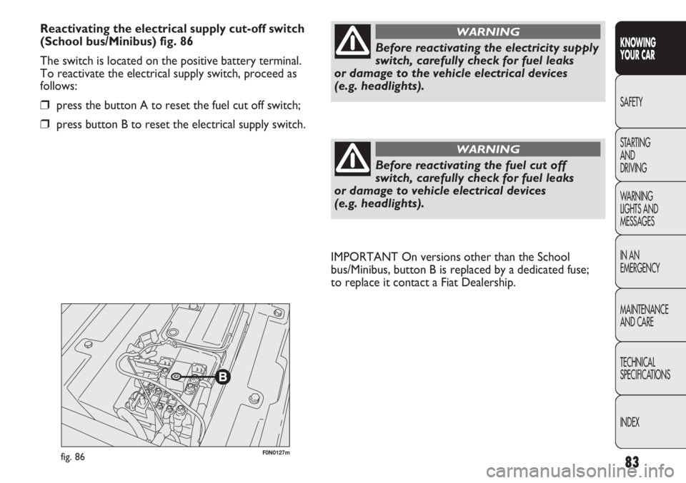
F0N0127mfig. 86
IMPORTANT On versions other than the School
bus/Minibus, button B is replaced by a dedicated fuse;
to replace it contact a Fiat Dealership.
Before reactivating the electricity supply
switch, carefully check for fuel leaks
or damage to the vehicle electrical devices
(e.g. headlights).
WARNING
Before reactivating the fuel cut off
switch, carefully check for fuel leaks
or damage to vehicle electrical devices
(e.g. headlights).
WARNING
Reactivating the electrical supply cut-off switch
(School bus/Minibus) fig. 86
The switch is located on the positive battery terminal.
To reactivate the electrical supply switch, proceed as
follows:
❒press the button A to reset the fuel cut off switch;
❒press button B to reset the electrical supply switch.
Page 88 of 287
84
KNOWING
YOUR CAR
SAFETY
STARTING
AND
DRIVING
WARNING
LIGHTS AND
MESSAGES
IN AN
EMERGENCY
MAINTENANCE
AND CARE
TECHNICAL
SPECIFICATIONS
INDEX
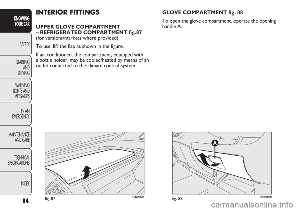
F0N0049mfig. 87
INTERIOR FITTINGS
UPPER GLOVE COMPARTMENT
– REFRIGERATED COMPARTMENT fig.87
(for versions/markets where provided)
To use, lift the flap as shown in the figure.
If air conditioned, the compartment, equipped with
a bottle holder, may be cooled/heated by means of an
outlet connected to the climate control system.GLOVE COMPARTMENT fig. 88
To open the glove compartment, operate the opening
handle A.
F0N0050mfig. 88
Page 89 of 287
85
KNOWING
YOUR CAR
SAFETY
STARTING
AND
DRIVING
WARNING
LIGHTS AND
MESSAGES
IN AN
EMERGENCY
MAINTENANCE
AND CARE
TECHNICAL
SPECIFICATIONS
INDEX
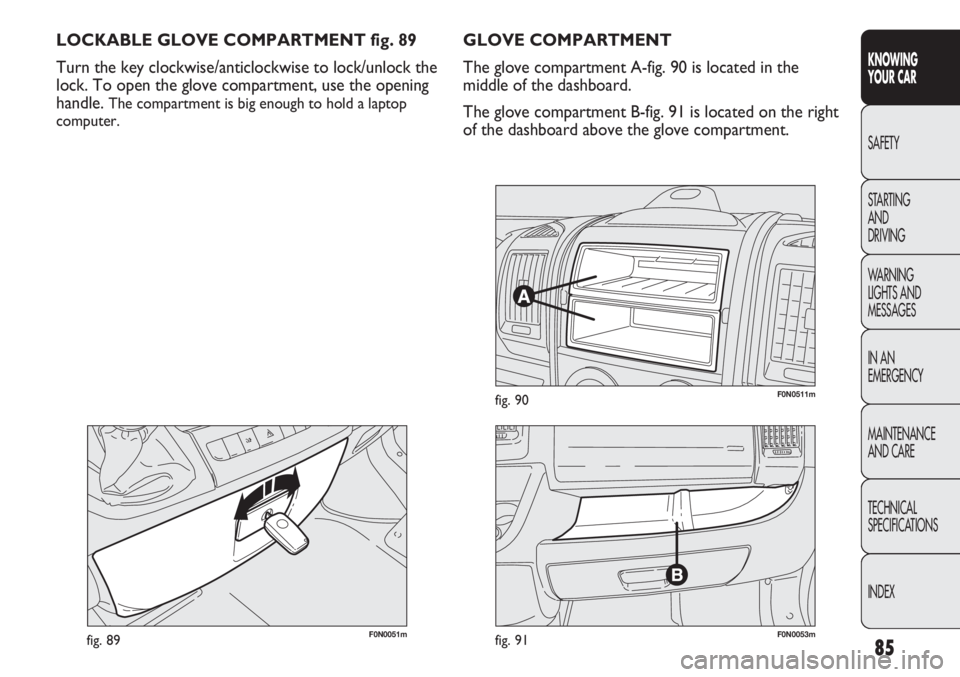
F0N0051mfig. 89
LOCKABLE GLOVE COMPARTMENT fig. 89
Turn the key clockwise/anticlockwise to lock/unlock the
lock. To open the glove compartment, use the opening
handle.
The compartment is big enough to hold a laptop
computer.
GLOVE COMPARTMENT
The glove compartment A-fig. 90 is located in the
middle of the dashboard.
The glove compartment B-fig. 91 is located on the right
of the dashboard above the glove compartment.
F0N0511mfig. 90
F0N0053mfig. 91
Page 90 of 287

86
KNOWING
YOUR CAR
SAFETY
STARTING
AND
DRIVING
WARNING
LIGHTS AND
MESSAGES
IN AN
EMERGENCY
MAINTENANCE
AND CARE
TECHNICAL
SPECIFICATIONS
INDEX
F0N0128mfig. 92F0N0134mfig. 93
COMPARTMENT BENEATH
PASSENGER SIDE FRONT SEAT fig. 93
Proceed as follows to use the compartment:
❒open the flap A and remove it as illustrated;
❒turn the lock knob B anticlockwise and remove it to
allow the removal of the compartment. DOOR POCKETS fig. 92
There are oddment/map pockets located in each of the
door panels.
Page 91 of 287
87
KNOWING
YOUR CAR
SAFETY
STARTING
AND
DRIVING
WARNING
LIGHTS AND
MESSAGES
IN AN
EMERGENCY
MAINTENANCE
AND CARE
TECHNICAL
SPECIFICATIONS
INDEX
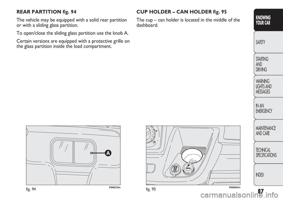
REAR PARTITION fig. 94
The vehicle may be equipped with a solid rear partition
or with a sliding glass partition.
To open/close the sliding glass partition use the knob A.
Certain versions are equipped with a protective grille on
the glass partition inside the load compartment.
F0N0218mfig. 94
CUP HOLDER – CAN HOLDER fig. 95
The cup – can holder is located in the middle of the
dashboard.
F0N0054mfig. 95
Page 92 of 287
88
KNOWING
YOUR CAR
SAFETY
STARTING
AND
DRIVING
WARNING
LIGHTS AND
MESSAGES
IN AN
EMERGENCY
MAINTENANCE
AND CARE
TECHNICAL
SPECIFICATIONS
INDEX
F0N0146mfig. 97F0N0055mfig. 96
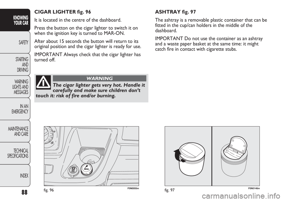
ASHTRAY fig. 97
The ashtray is a removable plastic container that can be
fitted in the cup/can holders in the middle of the
dashboard.
IMPORTANT Do not use the container as an ashtray
and a waste paper basket at the same time: it might
catch fire in contact with cigarette stubs. CIGAR LIGHTER fig. 96
It is located in the centre of the dashboard.
Press the button on the cigar lighter to switch it on
when the ignition key is turned to MAR-ON.
After about 15 seconds the button will return to its
original position and the cigar lighter is ready for use.
IMPORTANT Always check that the cigar lighter has
turned off.
The cigar lighter gets very hot. Handle it
carefully and make sure children don’t
touch it: risk of fire and/or burning.
WARNING
Page 93 of 287
89
KNOWING
YOUR CAR
SAFETY
STARTING
AND
DRIVING
WARNING
LIGHTS AND
MESSAGES
IN AN
EMERGENCY
MAINTENANCE
AND CARE
TECHNICAL
SPECIFICATIONS
INDEX
F0N0057mfig. 99F0N0056mfig. 98
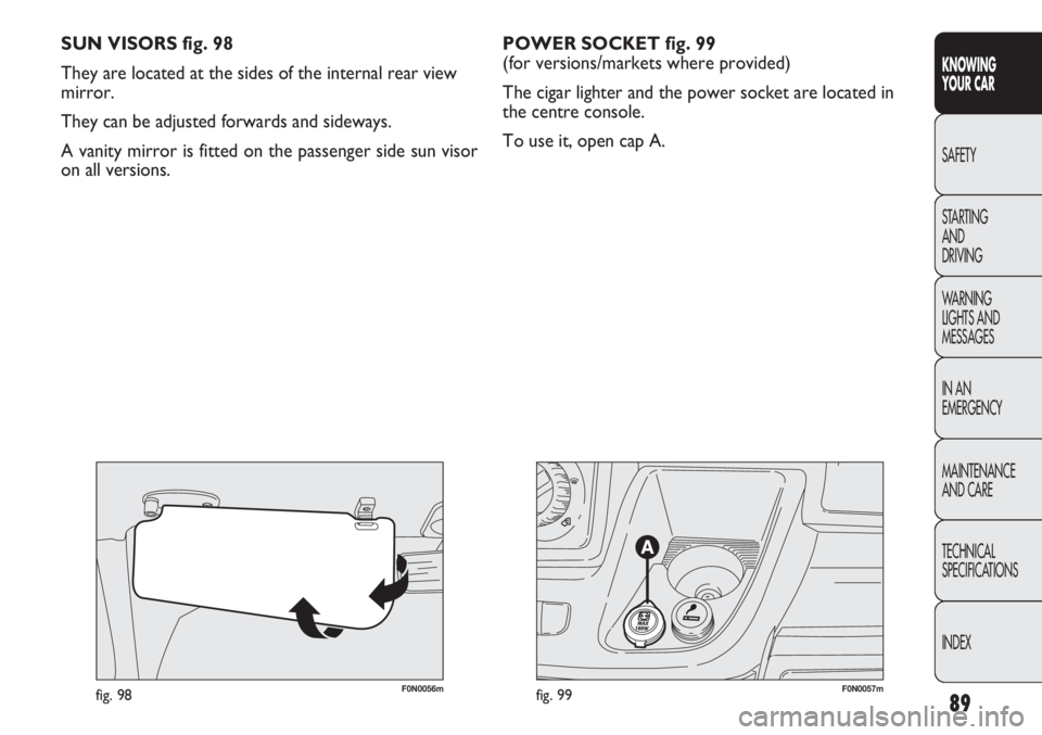
SUN VISORS fig. 98
They are located at the sides of the internal rear view
mirror.
They can be adjusted forwards and sideways.
A vanity mirror is fitted on the passenger side sun visor
on all versions.POWER SOCKET fig. 99
(for versions/markets where provided)
The cigar lighter and the power socket are located in
the centre console.
To use it, open cap A.
Page 94 of 287

90
KNOWING
YOUR CAR
SAFETY
STARTING
AND
DRIVING
WARNING
LIGHTS AND
MESSAGES
IN AN
EMERGENCY
MAINTENANCE
AND CARE
TECHNICAL
SPECIFICATIONS
INDEX
DESK/BOOKREST fig. 100
(for versions/markets where provided)
There is a desk A in the middle of the dashboard above
the sound system compartment; on some versions this
desk can be used as a bookrest by raising the back
section and resting it on the dashboard as illustrated in
the figure.
On versions with passenger side air bags, the desk is
fixed.
Do not use the desk in a vertical position
with the vehicle in motion.
WARNING
SHELF ABOVE THE CAB fig. 101
(for versions/markets where provided)
This is located above the driver’s cab and is designed to
store light objects.
Maximum permitted load:
– localised .........................................................................10 kg
– distributed over the entire surface of the shelf ....20 kg
F0N0058mfig. 100F0N0190mfig. 101
Page 95 of 287

91
KNOWING
YOUR CAR
SAFETY
STARTING
AND
DRIVING
WARNING
LIGHTS AND
MESSAGES
IN AN
EMERGENCY
MAINTENANCE
AND CARE
TECHNICAL
SPECIFICATIONS
INDEX
CAB GLOVE COMPARTMENT fig. 102
(for versions/markets where provided)
The storage compartment is fitted above the sun visors
and is designed for the quick storage of light objects
(e.g. documents, road maps etc.).
FLAP ON BENCH fig. 103
(for versions/markets where provided)
To use, the pull tab A and lower the flap.
The flap is equipped with two cup holders and a support
surface with a paper holder clip.
SATELLITE NAVIGATOR CAPABILITY fig. 104
(for versions/markets where provided)
This is located in the dashboard area illustrated in the
diagram for connecting the navigator.
F0N0191mfig. 102
F0N0149mfig. 103
F0N0512mfig. 104
Portable navigators to be fitted in the seat
in figure 104 have a mechanical release
device activated by pressing the two side
buttons on the stem. The failed operation of the
release may damage the seat of the navigator.
Page 96 of 287
92
KNOWING
YOUR CAR
SAFETY
STARTING
AND
DRIVING
WARNING
LIGHTS AND
MESSAGES
IN AN
EMERGENCY
MAINTENANCE
AND CARE
TECHNICAL
SPECIFICATIONS
INDEX
F0N0217mfig. 105F0N0214mfig. 106
The rear view display is adjusted in mirror mode. When
not in use, it must be closed in the upper oddments
compartment console area.
ACTIVATION
The system is activated with the ignition on and reverse
engaged or by means of a dedicated button. If the
vehicle is in motion, e.g. during a reversing manoeuvre,
the system will operate up to a speed of 15 km/h and go
off when a speed of approximately 18 km/h is exceeded.
When reverse is deactivated, the image will appear on
the display for a further 5 seconds. TV CAMERA SYSTEM
AND REAR VISIBILITY DISPLAY
(for versions/markets where provided)
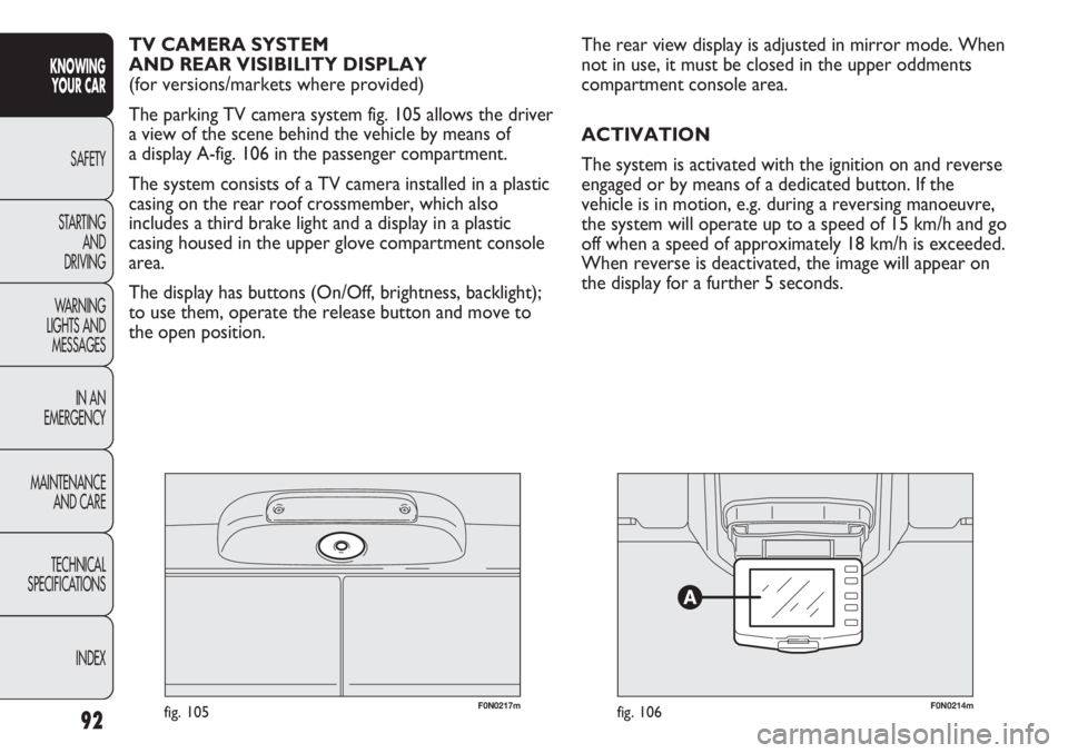
The parking TV camera system fig. 105 allows the driver
a view of the scene behind the vehicle by means of
a display A-fig. 106 in the passenger compartment.
The system consists of a TV camera installed in a plastic
casing on the rear roof crossmember, which also
includes a third brake light and a display in a plastic
casing housed in the upper glove compartment console
area.
The display has buttons (On/Off, brightness, backlight);
to use them, operate the release button and move to
the open position.