technical data FIAT QUBO 2017 1.G Owners Manual
[x] Cancel search | Manufacturer: FIAT, Model Year: 2017, Model line: QUBO, Model: FIAT QUBO 2017 1.GPages: 260, PDF Size: 4.74 MB
Page 176 of 260
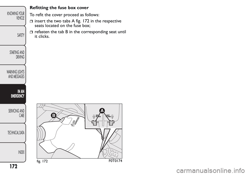
Refitting the fuse box cover
To refit the cover proceed as follows:
insert the two tabs A fig. 172 in the respective
seats located on the fuse box;
refasten the tab B in the corresponding seat until
it clicks.
fig. 172F0T0174
172
KNOWING YOUR
VEHICLE
SAFETY
STARTING AND
DRIVING
WARNING LIGHTS
AND MESSAGES
IN AN
EMERGENCY
SERVICING AND
CARE
TECHNICAL DATA
INDEX
Page 177 of 260
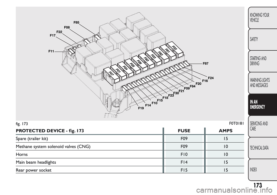
PROTECTED DEVICE - fig. 173 FUSE AMPS
Spare (trailer kit) F09 15
Methane system solenoid valves (CNG) F09 10
HornsF10 10
Main beam headlights F14 15
Rear power socket F15 15
fig. 173F0T0181
173
KNOWING YOUR
VEHICLE
SAFETY
STARTING AND
DRIVING
WARNING LIGHTS
AND MESSAGES
IN AN
EMERGENCY
SERVICING AND
CARE
TECHNICAL DATA
INDEX
Page 178 of 260
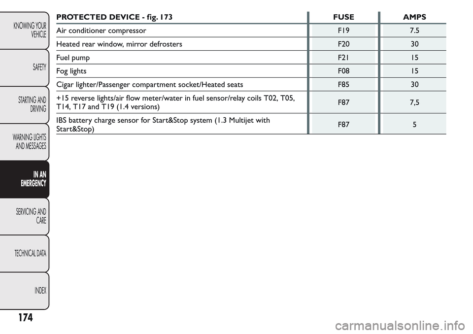
PROTECTED DEVICE - fig. 173 FUSE AMPS
Air conditioner compressor F19 7.5
Heated rear window, mirror defrosters F20 30
Fuel pump F21 15
Fog lights F08 15
Cigar lighter/Passenger compartment socket/Heated seats F85 30
+15 reverse lights/air flow meter/water in fuel sensor/relay coils T02, T05,
T14, T17 and T19 (1.4 versions)F87 7,5
IBS battery charge sensor for Start&Stop system (1.3 Multijet with
Start&Stop)F87 5
174
KNOWING YOUR
VEHICLE
SAFETY
STARTING AND
DRIVING
WARNING LIGHTS
AND MESSAGES
IN AN
EMERGENCY
SERVICING AND
CARE
TECHNICAL DATA
INDEX
Page 179 of 260
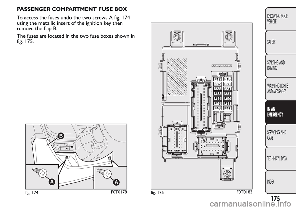
PASSENGER COMPARTMENT FUSE BOX
To access the fuses undo the two screws A fig. 174
using the metallic insert of the ignition key then
remove the flap B.
The fuses are located in the two fuse boxes shown in
fig. 175.
fig. 174F0T0178fig. 175F0T0183
175
KNOWING YOUR
VEHICLE
SAFETY
STARTING AND
DRIVING
WARNING LIGHTS
AND MESSAGES
IN AN
EMERGENCY
SERVICING AND
CARE
TECHNICAL DATA
INDEX
Page 180 of 260
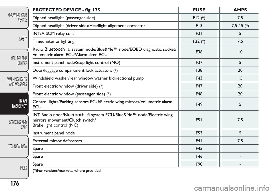
PROTECTED DEVICE - fig. 175 FUSE AMPS
Dipped headlight (passenger side)
F12
(*)7,5
Dipped headlight (driver side)/Headlight alignment corrector F13
7,5/5
(*)
INT/A SCM relay coils F31 5
Timed interior lighting
F32
(*)7,5
Radio
Bluetoothfisystem node/Blue&Me™ node/EOBD diagnostic socket/
Volumetric alarm ECU/Alarm siren ECUF36 10
Instrument panel node/Stop light control (NO) F37 5
Door/luggage compartment lock actuators
(*)F38 20
Windshield washer/rear window washer bidirectional pump F43 15
Front electric window (driver side)
(*)F47 20
Front electric window (passenger side)
(*)F48 20
Control lights/Parking sensors ECU/Electric wing mirrors/Volumetric alarm
ECUF49 5
INT Radio node/
Bluetoothfisystem ECU/Blue&Me™ node/Electric wing
mirrors movement/Clutch switch/
Brake light control (NC)F51 7.5
Instrument panel node F53 5
External mirror defrosters F41 7.5
SpareF45 -
SpareF46 -
SpareF90 -
(*)For versions/markets, where provided
176
KNOWING YOUR
VEHICLE
SAFETY
STARTING AND
DRIVING
WARNING LIGHTS
AND MESSAGES
IN AN
EMERGENCY
SERVICING AND
CARE
TECHNICAL DATA
INDEX
Page 181 of 260
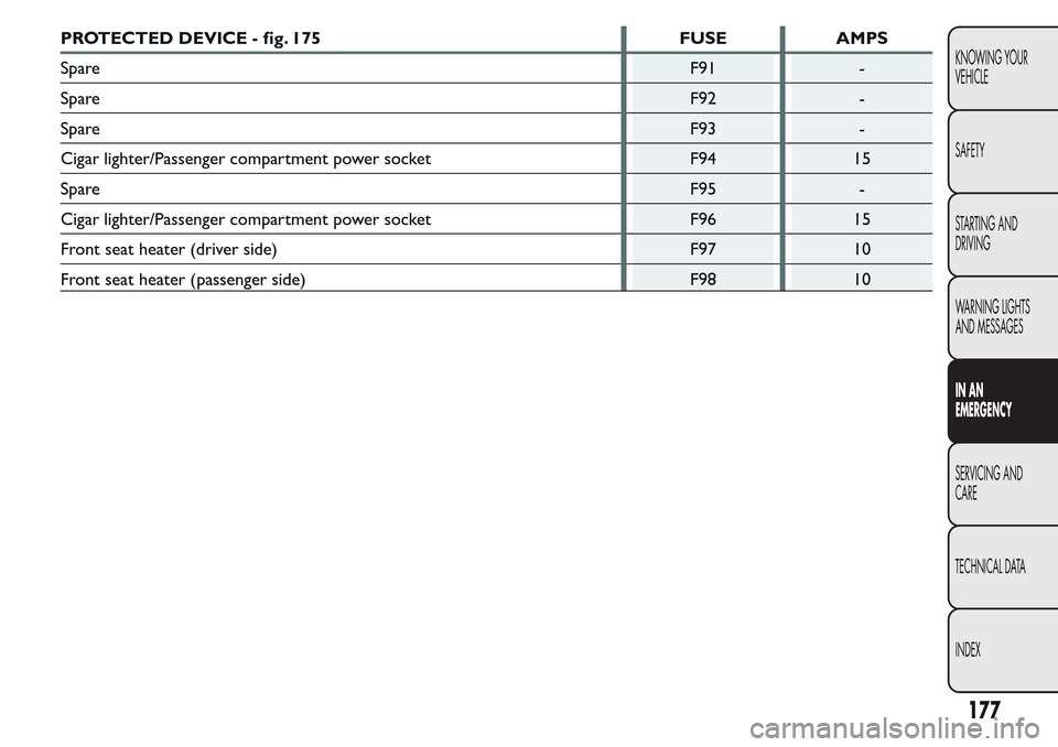
PROTECTED DEVICE - fig. 175 FUSE AMPS
SpareF91 -
SpareF92 -
SpareF93 -
Cigar lighter/Passenger compartment power socket F94 15
SpareF95 -
Cigar lighter/Passenger compartment power socket F96 15
Front seat heater (driver side) F97 10
Front seat heater (passenger side) F98 10
177
KNOWING YOUR
VEHICLE
SAFETY
STARTING AND
DRIVING
WARNING LIGHTS
AND MESSAGES
IN AN
EMERGENCY
SERVICING AND
CARE
TECHNICAL DATA
INDEX
Page 182 of 260
RECHARGING THE BATTERY
IMPORTANT The battery recharging procedure is
provided for information purposes only. You are
recommended to go to a Fiat Dealership to have this
operation performed.
We recommend recharging the battery slowly for
approximately 24 hours at low amperage. A
prolonged recharge might damage the battery.
Charge the battery as follows:
without Start&Stop system:
disconnect battery negative terminal;
connect the charger cables to the battery
terminals, observing the polarity;
turn on the charger;
when you have finished, turn the charger off
before disconnecting it from the battery;
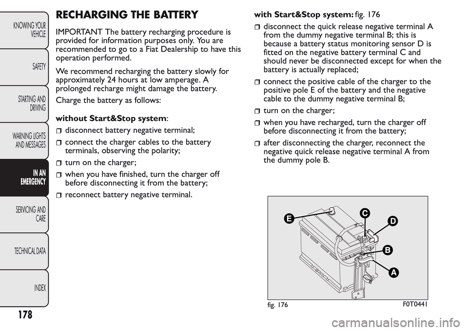
reconnect battery negative terminal.with Start&Stop system:fig. 176
disconnect the quick release negative terminal A
from the dummy negative terminal B; this is
because a battery status monitoring sensor D is
fitted on the negative battery terminal C and
should never be disconnected except for when the
battery is actually replaced;
connect the positive cable of the charger to the
positive pole E of the battery and the negative
cable to the dummy negative terminal B;
turn on the charger;
when you have recharged, turn the charger off
before disconnecting it from the battery;
after disconnecting the charger, reconnect the
negative quick release negative terminal A from
the dummy pole B.
fig. 176F0T0441
178
KNOWING YOUR
VEHICLE
SAFETY
STARTING AND
DRIVING
WARNING LIGHTS
AND MESSAGES
IN AN
EMERGENCY
SERVICING AND
CARE
TECHNICAL DATA
INDEX
Page 183 of 260
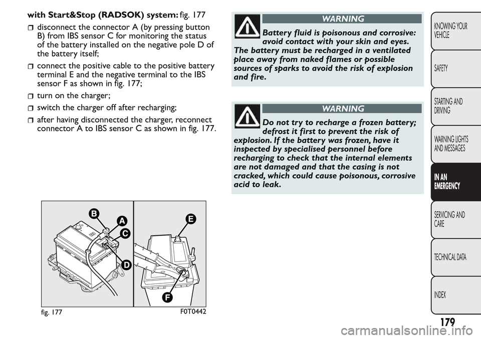
with Start&Stop (RADSOK) system:fig. 177
disconnect the connector A (by pressing button
B) from IBS sensor C for monitoring the status
of the battery installed on the negative pole D of
the battery itself;
connect the positive cable to the positive battery
terminal E and the negative terminal to the IBS
sensor F as shown in fig. 177;
turn on the charger;
switch the charger off after recharging;
after having disconnected the charger, reconnect
connector A to IBS sensor C as shown in fig. 177.
WARNING
Battery fluid is poisonous and corrosive:
avoid contact with your skin and eyes.
The battery must be recharged in a ventilated
place away from naked flames or possible
sources of sparks to avoid the risk of explosion
and fire.
WARNING
Do not tr y to recharge a frozen batter y;
defrost it first to prevent the risk of
explosion. If the battery was frozen, have it
inspected by specialised personnel before
recharging to check that the internal elements
are not damaged and that the casing is not
cracked, which could cause poisonous, corrosive
acid to leak.
fig. 177F0T0442
179
KNOWING YOUR
VEHICLE
SAFETY
STARTING AND
DRIVING
WARNING LIGHTS
AND MESSAGES
IN AN
EMERGENCY
SERVICING AND
CARE
TECHNICAL DATA
INDEX
Page 184 of 260
LIFTING THE VEHICLE
If the vehicle needs to be lifted, go to a Fiat
Dealership which is equipped with the arm hoist or
workshop lift.
TOWING THE VEHICLE
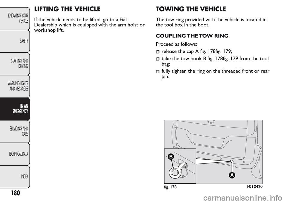
The tow ring provided with the vehicle is located in
the tool box in the boot.
COUPLING THE TOW RING
Proceed as follows:
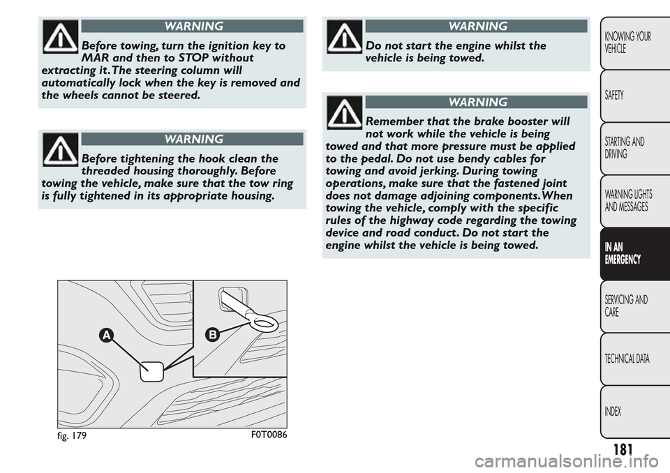
release the cap A fig. 178fig. 179;
take the tow hook B fig. 178fig. 179 from the tool
bag;
fully tighten the ring on the threaded front or rear
pin.
fig. 178F0T0420
180
KNOWING YOUR
VEHICLE
SAFETY
STARTING AND
DRIVING
WARNING LIGHTS
AND MESSAGES
IN AN
EMERGENCY
SERVICING AND
CARE
TECHNICAL DATA
INDEX
Page 185 of 260
WARNING
Before towing, turn the ignition key to
MAR and then to STOP without
extracting it .The steering column will
automatically lock when the key is removed and
the wheels cannot be steered.
WARNING
Before tightening the hook clean the
threaded housing thoroughly. Before
towing the vehicle, make sure that the tow ring
is fully tightened in its appropriate housing.
WARNING
Do not start the engine whilst the
vehicle is being towed.
WARNING
Remember that the brake booster will
not work while the vehicle is being
towed and that more pressure must be applied
to the pedal. Do not use bendy cables for
towing and avoid jerking. During towing
operations, make sure that the fastened joint
does not damage adjoining components.When
towing the vehicle, comply with the specific
rules of the highway code regarding the towing
device and road conduct . Do not start the
engine whilst the vehicle is being towed.
fig. 179F0T0086
181
KNOWING YOUR
VEHICLE
SAFETY
STARTING AND
DRIVING
WARNING LIGHTS
AND MESSAGES
IN AN
EMERGENCY
SERVICING AND
CARE
TECHNICAL DATA
INDEX